FIBARO Walli Controller
Important safety information
Read this manual before attempting to install the device!
Failure to observe recommendations included in this manual may be dangerous or cause a violation of the law. The manufacturer, Fibar Group S.A. will not be held responsible for any loss or damage resulting from not following the instructions of operating manual.
CAUTION!Risk of Explosion if battery is replaced by an incorrect type. Dispose of used batteries according to the instructions.
Do not modify!Do not modify this device in any way not included in this manual.
This product is intended for indoor use only in dry locations.Do not use in damp or wet locations, near a bathtub, sink, shower, swimming pool, or anywhere else where water or moisture are present.
Not a toy!This product is not a toy. Keep away from children and animals!
Description and features
Description
FIBARO Walli Controller is a smart wall-mounted Z-Wave™ remote controller that can activate scenes or control other Z-Wave devices via associations.
Main features
- Can be used for controlling multiple types of devices, e.g. switches, dimmers, roller shutters.
- Pre-set configurations allow to easily adjust operation for specific type of controlled devices.
- Battery or VDC powered.
- Equipped with a built-in temperature sensor.
- Supports Z-Wave network Security Modes: S0 with AES-128 encryption and S2 Authenticated with PRNG-based encryption.
- Works as a Z-Wave signal repeater when VDC powered (all non-battery operated devices within the network will act as repeaters to increase reliability of the network).
- May be used with all devices certified with the Z-Wave Plus™ certificate and should be compatible with such devices produced by other manufacturers.
The device is a Security Enabled Z-Wave Plus product and a Security Enabled Z-Wave Controller must be used in order to fully utilize the product.
Specifications
| Power supply | Battery and/or power supply unit |
| Battery type | ER14250 ½AA 3.6V (included) |
| Supply unit type | 5–24V DC, LPS or NEC class 2 (not included) |
| Battery life | est. 2 years (with default settings and max. 10 pushes per day) |
| Operating temperature | 0–40°C |
| Ambient humidity | 0–90% RH without condensation |
| Temperature measure- ment accuracy | ±0.5°C |
| Radio protocol | Z-Wave (700 series chip) |
| Radio frequency band | 868.0–868.6MHz; 869.7–870.0MHz |
| Max. transmitting power | +13dBm |
| Range | up to 50m outdoors up to 40m indoors
(depending on terrain and building structure) |
| Dimensions
(Height x Width x Depth) |
86 x 86 x 20 mm |
| Compliance with EU directives | RoHS 2011/65/EU RoHS 2015/863 RED 2014/53/EU |
Radio frequency of individual device must be same as your Z-Wave controller. Check information on the box or consult your dealer if you are not sure.
First installation
You can install the device on any smooth surface using included stickers or on a mounting box using screws.
The device will select the powering mode during adding to the Z-Wave network, prioritizing external power supply if connected. To change the mode after adding, you must change the installation accordingly, then remove and add the device again.
The device features a built-in temperature sensor, for ac- curate temperature readings, install the device far from sources of heat (e.g. radiators, power supplies)
Installing on a smooth surface with battery supply
- Remove the button cover
- Remove the paper strip protecting the battery
- LED ring light means the device is powered
- Insert the button cover back
- Remove the mounting frame from the device
- Use the included double-sided stickers to stick the mounting frame to the smooth surface
- Push the device onto the mounting frame of the device, you should hear an audible click
Installing on a mounting box with battery supply
- Remove the mounting frame from the device
- Place the mounting frame onto the mounting box and secure it with screw
- Push the device onto the mounting frame of the device, you should hear an audible clicks
- Remove the button cover
- Remove the paper strip protecting the battery
- LED ring light means the device is powered
- Insert the button cover back
Installing on a mounting box with an external power supply
Prepare the power supply
- Switch off the mains voltage (disable the fuse).
- Disable the power supply
- Using wire connectors, connect included power connector to the power supply (black to negative wire, red to positive wire).
- Using wire connectors, connect the power supply to the mains
- Place the power supply inside the mounting box, leaving the power connector outside
- Remove the mounting frame from the device.
- Push the power connector through hole in the mounting frame.
- Place the mounting frame onto the mounting box and secure it with screws.
- Plug the power connector into the device.
- Push the device onto the mounting frame of the device, you should hear an audible click.
- Switch on the mains voltage.
- LED ring light means the device is powered.
- Remove the button cover.
- Remove the paper strip protecting the battery if you want to use it as emergency power source, remove the battery otherwise.
- Insert the button cover back.
Adding to Z-Wave network
Adding (Inclusion) – Z-Wave device learning mode, allowing to add the device to existing Z-Wave network
The device will select the powering mode during adding to the Z-Wave network, prioritizing external power supply if connected. To change the mode after adding, you must change the installation accordingly, then remove and add the device again.
Adding manually
To add the device to the Z-Wave network manually:
- Set the main controller in (Security/non-Security Mode) add mode (see the controller’s manual).
- Quickly, three times click one of the buttons.
- If you are adding in Security S2 Authenticated, input the underlined part of the DSK (label on the bottom of the box).
- LED will start blinking yellow, wait for the adding process to end.
- Adding result will be confirmed by the Z-Wave controller’s message and the LED frame:
- Green – successful (non-secure, S0, S2 non-authenticated),
- Magenta – successful (Security S2 Authenticated),
- Red – not successful.
Adding using SmartStart
SmartStart enabled products can be added into a Z-Wave network by scanning the Z-Wave QR Code present on the product with a controller providing SmartStart inclusion. SmartStart product will be added automatically within 10 minutes of being switched on in the network range.
To add the device to the Z-Wave network using SmartStart:
- To use SmartStart your controller needs to support Security S2 (see the controller’s manual).
- Enter the full DSK string code to your controller. If your controller is capable of QR scanning, scan the QR code placed on the label on the bottom of the box.
- Power the device.
- Wait for the adding process to start (up to few minutes), which is signaled with yellow LED blinking.
- Adding result will be confirmed by the Z-Wave controller’s message and the LED frame:
- Green – successful (non-secure, S0, S2 non-authenticated),
- Magenta – successful (Security S2 Authenticated),
- Red – not successful.
In case of problems with adding the device, please reset the device and repeat the adding procedure.
Removing from Z-Wave network
Removing (Exclusion) – Z-Wave device learning mode, allowing to remove the device from existing Z-Wave network. Removing also results in resetting the device to factory defaults.
To remove the device from the Z-Wave network:
- Set the main controller into remove mode (see the controller’s manual).
- Quickly, three times click, then press and hold one of the buttons for 12 seconds.
- Release the button when the device glows green.
- Quickly click the button to confirm.
- LED will start blinking yellow, wait for the removing process to end.
- Successful removing will be confirmed by the Z-Wave controller’s message and red LED colour.
Operation
Controls
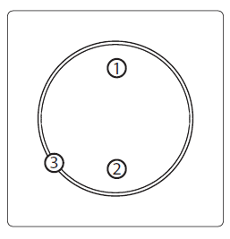
- First/ button,
- Second/ button,
- LED ring.
Operating modes
Scene Controller: This mode is enabled by default or by setting parameter 20 to 0. In this mode, the device can activate scenes in the Z-Wave controller by sending scene ID and attribute of a specific action (using Central Scene Command Class). Associations do not work in this mode.
| Button | Action | Scene ID | Attribute |
| 1st button | Clicked once | 1 | Key Pressed 1 time |
| Clicked twice | 1 | Key Pressed 2 times | |
| Clicked thrice | 1 | Key Pressed 3 times | |
| Held | 1 | Key Held Down | |
| Released | 1 | Key Released | |
| 2nd button | Clicked once | 2 | Key Pressed 1 time |
| Clicked twice | 2 | Key Pressed 2 times | |
| Clicked thrice | 2 | Key Pressed 3 times | |
| Held | 2 | Key Held Down | |
| Released | 2 | Key Released |
Double Button:This mode is enabled by setting parameter 20 to 1.In this mode the device works as two separate buttons and it usesassociations to control other Z-Wave devices (groups 2-5). You cancontrol multiple devices of different type in this mode. Every buttoncan control different group of device.
- Click – ON/OFF alternately
- 2xClick – send pre-set level (set in parameter 152 and 153)
- Hold – increase/decrease level alternately until released
Single 3-position ButtonThis mode is enabled by setting parameter 20 to 2. In this mode the device works as one 3-position button and it uses associations to control other Z-Wave devices (groups 2-3). You can control multiple devices of different type in this mode.
- Click – ON/OFF alternately
- 2xClick – send pre-set level (set in parameter 152)
- Hold – increase/decrease level alternately until released
Switch ControllerThis mode is enabled by setting parameter 20 to 3. In this mode the device uses associations to control Z-Wave binary switches (group 6).
- Click 1st – ON
- Click 2nd – OFF
Dimmer ControllerThis mode is enabled by setting parameter 20 to 4. In this mode the device uses associations to control Z-Wave dimmers (group 6).
- Click 1st – ON
- Hold 1st – brighten until released
- 2xClick 1st – send pre-set level (set in parameter 152)
- Click 2nd – OFF
- Hold 2nd – dimm until released
Roller Shutter ControllerThis mode is enabled by setting parameter 20 to 5. In this mode the device uses associations to control Z-Wave roller shutter controllers (group 6).
- Click 1st when stopped – open
- Click 2nd when stopped – close
- Click 1st/2nd when moving – stop
- 2xClick 1st – send pre-set level (set in parameter 152)
- 2xClick 2nd – stop
Venetian blinds ControllerThis mode is enabled by setting parameter 20 to 6. In this mode the device uses associations to control Z-Wave venetian blinds (with slats) controllers (groups 6-7).
- Click 1st when stopped – open
- Click 2nd when stopped – close
- Click 1st/2nd when moving – stop
- 2xClick 1st – send pre-set level (set in parameter 152)
- 2xClick 2nd – stop
- Hold 1st – open slats until released
- Hold 2nd – close slats until released
Powering modes
External supply modeIn external supply mode, the device indicates commands status and can receive indications from the Z-Wave controller (using Indicator CC), including Identification.Device configuration is updated immediately.
To enable the external supply mode, make sure that the external supply is connected and powered, then add the device to the Z-Wave network (remove beforehand if already added).
Battery modeIn battery mode, the device indicates commands status, but cannot receive indications from the Z-Wave controller (using Indicator CC), except for Identification.
The device needs to be woken up to change its configuration. The battery level (in percent) is measured during every power up and periodically every 24h, the measured value is reported to the controller during every power up and when it changes by at least 5%.
To enable the battery mode, make sure that device is powered only using the battery, then add the device to the Z-Wave network (remove beforehand if already added).
Temperature sensor
The device is equipped with a built-in temperature sensor. It measures the ambient temperature every 5 minutes, and reports it to the controller only when it changes by at least 0.5°C.
Waking up
When on battery power, the device needs to be woken up to receive information about the new configuration from the Z-Wave controller, like parameters and associations. By default the device is woken up automatically every 6 hours.You can wake up the device manually using white menu position.
Visual indications
The built-in LED light shows current device status.
After powering the device:
- Green – device added to a Z-Wave network (non-secure, S0, S2 non-authenticated),
- Magenta – device added to a Z-Wave network (Security S2 Authenticated),
- Red – device not added to a Z-Wave network.
Update:
- Blinking cyan – update in progress,
- Green – update successful,
- Red – update not successful.
Command status:The device displays current command status in response to clicking/ holding the button.
- Green for 2 seconds – command acknowledged,
- Yellow for 2 seconds – command during routing,
- Green for 2 seconds – command not acknowledged.
When holding the button, the device will periodically brighten (when increasing the level) or dimm (when decreasing the level) the LED ring with white colour, then only after realising will indicate command status.
Identification:The Z-Wave controller can identify this device by blinking red with whole LED ring (using Indicator CC).
Custom indications:In external supply mode, the user can use the LED ring to display custom indications. Using the Z-Wave controller user can specify on which half of the ring to indicate, number of blinks and timing (using Indicator CC). Brightness and colour of the indications is specified in parameters 13, 150 and 151.
Resetting to factory defaults
Reset procedure allows to restore the device back to its factory settings, which means all information about the Z-Wave controller and user configuration will be deleted.
Resetting the device is not the recommended way of removing the device from the Z-Wave network. Use reset procedure only if the primary controller is missing or inoperable. Certain device removal can be achieved by the procedure of removing described.
- Quickly, three times click, then press and hold one of the buttons for 21 seconds.
- Release the button when the device glows yellow.
- Quickly click the button to confirm.
- After a few seconds the device will be restarted, which is signaled with red LED colour.
Configuration
Associations
Association (linking devices) – direct control of other devices within the Z-Wave system network.Associations allow:
- Reporting the device status to the Z-Wave controller (using Lifeline group),
- creating simple automations by controlling other devices without participation of the main controller (using groups assigned to actions on the device).
The device provides the association of 7 groups:
1st association group – “Lifeline” reports the device status and allows for assigning single device only (main controller by default).2nd association group – “On/Off (1)” is used to turn the associated devices on/off.3rd association group – “Dimmer (1)” is used to change level of associated devices.4th association group – “On/Off (2)” is used to turn the associated devices on/off.5th association group – “Dimmer (2)” is used to change level of associated devices.6th association group – “Multidevice” is used to control different type of devices.7th association group – “Slats” is used to move slats of venetian blinds.
The device allows to control 5 regular or multichannel devices per an association group, with the exception of “LifeLine” that is reserved solely for the controller and hence only 1 node can be assigned
Commands sent to association groups in Double Button Mode (parameter 20 set to 1)
| 1 click | 2 click | Hold | Release | |
|
Button 1 |
Basic Set: 2nd group |
Basic Set: 2nd group |
Multilevel Start Change: 3rd group | Multilevel Stop Level Change: 3rd group |
|
Button 2 |
Basic Set: 4th group |
Basic Set: 4th group |
Multilevel Start Change: 5th group | Multilevel Stop Level Change: 5th group |
Commands sent to association groups in 3-position Single Button Mode (parameter 20 set to 2)
| 1 click | 2 click | Hold | Release | |
|
Button 1 and 2 |
Basic Set: 2nd group |
Basic Set: 2nd group |
Multilevel Start Change: 3rd group | Multilevel Stop Level Change: 3rd group |
Commands sent to association groups in Switch Controller Mode (parameter 20 set to 3)
| 1 click | 2 click | Hold | Release | |
| Button 1 (on) | Basic Set: 6th group |
– |
– |
– |
| Button 2 (off) | Basic Set: 6th group |
– |
– |
– |
Commands sent to association groups in Dimmer Controller Mode (parameter 20 set to 4)
| 1 click | 2 click | Hold | Release | |
|
Button 1 (on) |
Multilevel Set: 6th group | Multilevel Set: 6th group | Multilevel Start Change: 6th group | Multilevel Stop Level Change: 6th group |
Commands sent to association groups in Roller Shutter / Gate Controller Mode (parameter 20 set to 5)
| 1 click | 2 click | Hold | Release | |
|
Button 1 (up) |
Multilevel Start/Stop Change: 6th group | Multilevel Set: 6th group |
– |
– |
| But- ton 2 (down) | Multilevel Start/Stop Change: 6th group | Multilevel Set: 6th group |
– |
– |
Commands sent to association groups in Roller Shutter / Gate Controller Mode (parameter 20 set to 6)
| 1 click | 2 click | Hold | Release | |
|
Button 1 |
Multilevel Set: 6th group | Multilevel Set: 6th group | Multilevel Start/Stop Change: 7th group | Multilevel Start/Stop Change: 7th group |
|
Button 2 |
Multilevel Set: 6th group | Multilevel Set: 6th group | Multilevel Start/Stop Change: 7th group | LMultilevel Start/Stop Change: 7th group |
Advanced parameters
The device allows to customize its operation to user’s needs using configurable parameters.
The settings can be adjusted via Z-Wave controller to which the device is added. The way of adjusting them might differ depending on the controller.In the FIBARO interface parameters are presented as simple options in Advanced Settings of the device.
Available parameters:
| 13. | LED frame – brightness |
| Description | This parameter allows to adjust the LED frame brightness. |
| Parameter size | 1B |
| Default value | 100 (100%) |
| Available values | 0 – LED disabled
1-100 (1-100% brightness) |
| 20. | Operation mode |
| Description | This parameter defines operation of the device. Choose the mode depending on the type of the device you want to control remotely |
| Parameter size | 1B |
| Default value | 0 (scene controller) |
| Available values | 0 – scene controller mode 1 – double button mode
2 – 3-position single button mode 3 – switch controller mode 4 – dimmer controller mode 5 – roller shutter / gate controller mode (step-by-step) 6 – venetian blinds controller mode (step-by-step) |
| 150. | LED ring – first button |
|
Description |
This parameter defines the colour of first button indicator (upper part of the LED ring) for indica- tions using Indicator CC. |
| Parameter size | 2B |
| Default value | 1 (white) |
|
Available values |
0 – LED disabled 1 – White
2 – Red 3 – Green 4 – Blue 5 – Yellow 6 – Cyan 7 – Magenta 8 – LAPD (blinking red-white-blue) |
| 151. | LED ring – second button |
| Description | This parameter defines the colour of second button indicator (lower part of the LED ring) for indications using Indicator CC. |
| Parameter size | 2B |
| Default value | 1 (white) |
| Available values | 0 – LED disabled 1 – White
2 – Red 3 – Green 4 – Blue 5 – Yellow 6 – Cyan 7 – Magenta 8 – LAPD (blinking red-white-blue) |
| 152. | 1st button – double click value |
| Description | This parameter defines value of Basic Set or Multilevel Set frame (depending on selected mode) sent to associated devices after double click. This parameter is not relevant for Scene Controller Mode. |
| Parameter size | 2B |
| Default value | 99 |
| Available values | 0-99 or 255 |
| 153. | 2nd button – double click value |
| Description | This parameter defines value of Basic Set or Multilevel Set frame (depending on selected mode) sent to associated devices after double click. This parameter is not relevant for Scene Controller Mode. |
| Parameter size | 2B |
| Default value | 99 |
| Available values | 0-99 or 255 |
Z-Wave specification
Generic Device Class: GENERIC_TYPE_WALL_CONTROLLERSpecific Device Class: not used
Supported Command Classes
| Command Class | Version | Secure | |
| 1. | COMMAND_CLASS_ZWAVEPLUS_INFO [0x5E] | V2 | |
| 2. | COMMAND_CLASS_ASSOCIATION [0x85] | V2 | YES |
| 3. | COMMAND_CLASS_MULTI_CHANNEL_ASSOCI- ATION [0x8E] | V3 | YES |
| 4. | COMMAND_CLASS_ASSOCIATION_GRP_INFO [0x59] | V3 | YES |
| 5. | COMMAND_CLASS_INDICATOR [0x87] | V3 | YES |
| 6. | COMMAND_CLASS_TRANSPORT_SERVICE [0x55] | V2 | |
| 7. | COMMAND_CLASS_VERSION [0x86] | V3 | YES |
| 8. | COMMAND_CLASS_MANUFACTURER_SPECIFIC [0x72] | V2 | YES |
| 9. | COMMAND_CLASS_DEVICE_RESET_LOCALLY [0x5A] | V1 | YES |
| 10. | COMMAND_CLASS_POWERLEVEL [0x73] | V1 | YES |
| 11. | COMMAND_CLASS_SECURITY [0x98] | V1 | |
| 12. | COMMAND_CLASS_SECURITY_2 [0x9F] | V1 | |
| 13. | COMMAND_CLASS_SUPERVISION [0x6C] | V1 | |
| 14. | COMMAND_CLASS_CONFIGURATION [0x70] | V4 | YES |
| 15. | COMMAND_CLASS_FIRMWARE_UPDATE_MD [0x7A] | V5 | YES |
| 16. | COMMAND_CLASS_CENTRAL_SCENE [0x5B] | V3 | YES |
| 17. | COMMAND_CLASS_SENSOR_MULTILEVEL [0x31] | V11 | YES |
| 18. | COMMAND_CLASS_APPLICATION_STATUS [0x22] | V1 | |
| 19. | COMMAND_CLASS_PROTECTION [0x75] | V1 | YES |
| Only in battery mode | |||
| 20. | COMMAND_CLASS_WAKE_UP [0x84] | V2 | YES |
| 21. | COMMAND_CLASS_BATTERY [0x80] | V1 | YES |
Wake Up CC (only in battery mode)
| Min. Interval Seconds | 0 – off, 3600 [s] = 1 [h] |
| Max. Interval Seconds | 43200 [s] = 12[h] |
| Default Interval Seconds | 21600 [s] = 6 [h] |
| Interval Step Seconds | 3600 |
| Default NodeID | 255 |
| Additional Sending Frame | Menu – white position |
Indicator CC – available indicators
Button 1 Indicator – 0x43 – only in always on (external supply) modeButton 2 Indicator – 0x44 – only in always on (external supply) modeIndicator ID – 0x50 (Identify)
Indicator CC – available commands
| Command | Indicator ID | Property ID | Value | Other |
| SET | All | 0x03 | 0x00 – 0xFF | |
| SET | All | 0x04 | 0x00 – 0xFF | |
| SET | All | 0x05 | 0x00 – 0xFF | |
| GET | All | – | – | Device send Indica- tor Report |
| SUPPORTED GET | All | – | – | Device send Sup- ported Report |
Indicator CC – properties
| Property ID | Description | Values and requirements |
| 0x03 | On/Off Periods | Starts toggling between ON and OFF Used to set the duration of an On/Off pe- riod.
Available values: • 0x00 .. 0xFF (0 .. 25.5 seconds) If this is specified, the On/Off Cycles MUST also be specified. |
| 0x04 | On/Off Cycles | Used to set the number of On/Off periods. Available values:
• 0x00 .. 0xFE (0 .. 254 times) • 0xFF (indicate until stopped) If this is specified, the On/Off Period MUST also be specified. |
| 0x05 | On time with- in an On/Off period | Used to set the length of the On time dur- ing an On/Off period. It allows asymetic On/Off periods.
Available values • 0x00 (symmetric On/Off period – On time equal to Off time) • 0x01 .. 0xFF (0.1 .. 25.5 seconds) Example: 300ms ON and 500ms OFF is achieved by setting On/Off period (0x03) = 0x08 and On time within an On/Off Period (0x05) = 0x03 This value is ignored if On/Off periods is not defined. This value is ignored if On/Off periods value is less than this value. |
Protection CC
Protection Command Class allows to prevent local control using buttons.
| Type | State | Description | Hint |
| Local | 0 | Unprotected – The device is not protected, and may be operated normally via the user interface. | Inputs control radio |
| Local | 2 | Buttons cannot send control frames e.g Basic, Switch Multilev- el, other functionality is available (menu) |
Inputs do not control radio |
Sensor Multilevel CC
| Sensor Type | Scale | Size | Precision | Description |
| Temperature | Celsius (C) | 2B | 1 | Air temperature |
Regulations
Legal NoticesAll information, including, but not limited to, information regarding the features, functionality, and/or other product specification are subject to change without notice. Fibar Group S.A. reserves all rights to revise or update its products, software, or documentation without any obligation to notify any individual or entity.FIBARO and Fibar Group logo are trademarks of Fibar Group S.A. All other brands and product names referred to herein are trademarks of their respective holders.
Declaration of conformityHereby, Fibar Group S.A. (with its registered office in Wysogotowo, ul. Serdeczna 3, 62-081 Wysogotowo) declares that the device is in compliance with the essential requirements and other relevant provisions of Directive 2014/53/EU. The full text of the EU declaration of conformity is available at the following internet address: www.manuals.fibaro.com
WEEE Directive ComplianceDevice labelled with this symbol should not be disposed with other household wastes. It shall be handed over to the applicable collection point for the recycling of waste electrical and electronic equipment.

References
[xyz-ips snippet=”download-snippet”]