
Sanctuary Series Outdoor Fire FeaturesUser Manual
Do not discard. This manual has important operating and maintenance instructions.Leave with the homeowner.MODEL:_______________________SERIAL #______________________
The round flat disc system for the sanctuary 2 & 3 comes in a separate carton however, use this manual for actual installation into the sanctuary bowls

MODELS
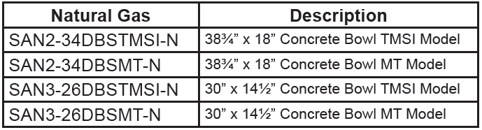
Sanctuary Series Outdoor Fire Features
Installation and Operating Instructions
NOTE:
- If you cannot read or understand these installation instructions
- Do not attempt to install or operate this appliance
Ventilation is incorporated into all Sanctuary Series Fire Features

WARNING
If the information in these instructions is not followed exactly, a fire or explosion may result causing property damage, personal injury or death.
FOR YOUR SAFETY
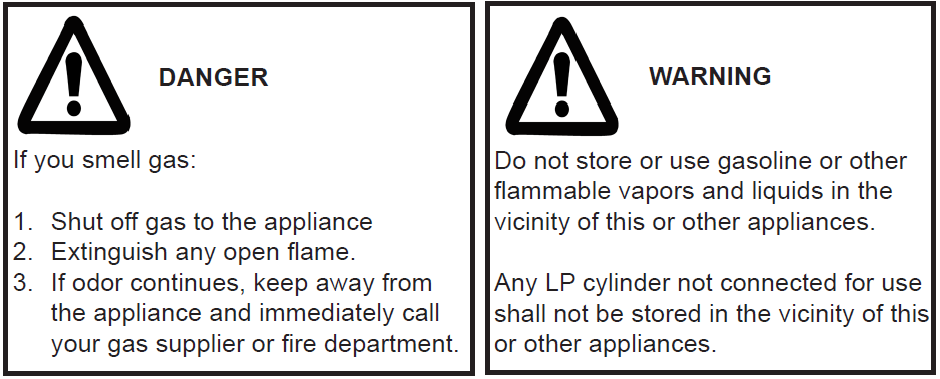
Do not store or use gasoline or other flammable vapors and liquids in the vicinity of this or other appliances.
DANGER: Fuels used in gas fired appliances, and the products of combustion such as fuels, contain chemicals known to cause cancer, birth defects and/or other reproductive harm.This warning is issued pursuant to the California Health & Safety Code Sec. 25249.1
CALIFORNIA PROPOSITION 65
WARNING
This product is designed to operate with one of the following fuel sources: Liquid Propane or Natural Gas. The fuel used to operate this product, and the products of combustion of such fuel, can expose you to chemicals including Benzene which is known to the State of California to cause cancer, birth defects and other reproductive harm and Carbon Monoxide which is known to the State of California to cause birth defects or other reproductive harm. (For more information go to: www.p65Warnings.ca.gov.)
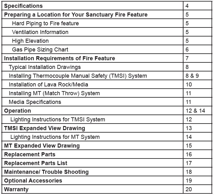
TABLE OF CONTENTS
DANGER
All media (i.e. lava rock, lava stones, lava boulders and fire glass) has the potential of thermal spalling. This is a process that may occur when media is wet and moisture gets trapped inside of the material due to rapid temperature differences. When this happens the media has the potential to crack or “pop” outside the fireplace.
WE HIGHLY RECOMMEND COVERING ALL FIRE FEATURES WHEN NOT IN USE
The use of a cover can lessen the impact of thermal spalling; however, heavy rains, high humidity and the presence of moisture may still cause the media to pop.
ALWAYS USE CAUTION WHEN USING THE FIRE FEATURE
Extra caution should be taken when lighting a fireplace when heavy rains, high humidity and moisture are present. Light the fireplace; leave the area allowing any moisture in the media to dissipate. We strongly recommend that during this drying out time that you monitor the fire feature from a distance. This drying out period should be no less than 30 minutes. Continue monitoring
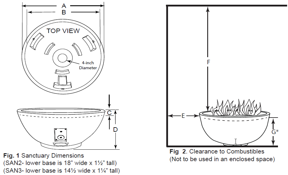
SANCTUARY SPECIFICATIONS
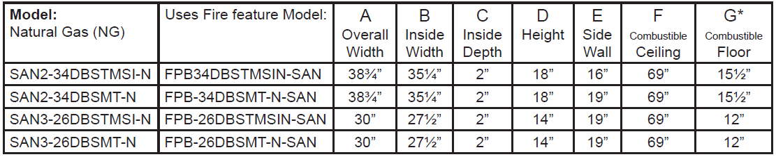
* Dimension shows disc/pan from combustible floor sitting inside the Sanctuary bowl (See Fig. 2).
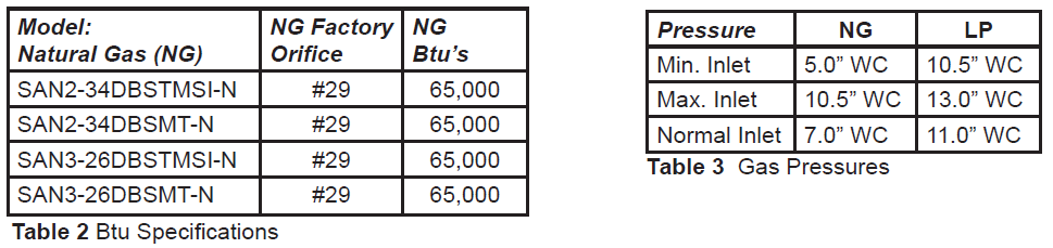
Disclaimer: Btu listings are based on 7.0”WC for Natural Gas and 11.0”WC for Liquid Propane (LP) to the gas valve. Flex line size and proper gas pipe sizing will also affect Btu’s. As a result your Btu’s may vary slightly from Table 2 specifications.
WARNING: Proper clearances from combustible materials must be maintained from all sides, top and bottom of this appliance. Use the specifications listed for proper clearance to combustibles.
PREPARING A LOCATION FOR FIRE FEATURE
NOTE: The Sanctuary Series fire features/bowls are constructed of Glass Fiber Reinforced Concrete (GFRC). The Sanctuary 2 weighs 166lbs without media or the burner system installed. The Sanctuary 3 weighs 92lbs without media orthe burner system installed. Ensure the structure you are placing these fire features on is solid enough to securely hold the weight. IT IS HIGHLY RECOMMENDED FOR AT LEAST 2-3 PEOPLE TO ASSIST IN MOVING THE FIRE FEATURES INTO PLACE.
Each fire feature can be installed on a flat, stable surface, away from any combustible materials. Install the fire features on any level, flat, stable, non-combustible surface. NOTE: Do not place fire features directly on grass, dirt, or rocks as this may prevent proper ventilation. Water drainage is designed into all Sanctuary Series fire features. Ensure not to block/plug the drains areas to prevent potential damage to your fire feature.
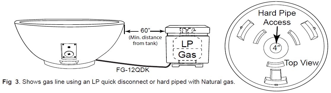
The Sanctuary 2 and 3 can be plumbed with either Natural or Propane (LP) gas. See Fig. 3. If you choose to run hard pipe to Sanctuary models enter through center (bottom) of the bowl; protrude pipe no higher than 6” above ground level.
HARD PIPING TO FIRE FEATURE WITHOUT GAS PROXIMITY
NOTE: Refer to the NFPA54 (National Fuel Gas Code) for proper pipe sizing. See gas line sizing chart on page 6 of this manual as a reference.
- Turn OFF gas supply system. NOTE: All gas connections (except for brass to brass) require the following. Clean pipe threads using either a wire brush or steel wool. Apply pipe sealant to the fittings before making any connection.
- BE CAREFUL! Ensure all gas connections are snug, but do not over tighten!
- Consult a plumber for proper installation to ensure you are providing adequate gas supply for your application.
- The primary gas shut-off (not supplied) will require a ⅜” male flared fitting to enable connection of the stainless steel flex gas line supplied with the fire feature.
FLEXIBLE PIPING TO FIRE FEATURE
- Do not place an LP tank inside any fire feature enclosure. Locate all propane (LP) tanks outside the enclosure inside an approved seperate enclosure a minimum of 60” from the Sanctuary 1. Flex line can run through any vent holes.
- If using Propane gas an FG-LPRK regulator (not included) must be used and a FG-12QDK-2 quick disconnect kit (not supplied) enables the use of a Propane (LP) gas tank connection. See Fig. 3.
IMPORTANTInstallation of Natural or LP gas should be done by a qualified installer, service agency or gas supplier.The appliance and its manual shutoff valve must be disconnected from the gas supply piping system during anypressure testing of the system at test pressure testing of the system at test pressures in excess of ½” psig (3.5kPa).This appliance must be isolated from the gas supply piping system by closing its manual shutoff valve during any pressure testing of the gas supply piping system at test pressures equal to or less than ½” psig (3.5kPa)
VENTILATIONVentilation is built into the bottom of each concrete fire feature. No additional vents are required. WARNING: DO NOT BURY THE BOTTOM OF THE CONCRETE BOWL INTO EARTH OR OTHER TYPE OF MEDIA . THIS CAN OBSTRUCT AIR FLOW VENTILATION AND VOID FIREGEAR WARRANTY
HIGH ELEVATION INSTALLATIONThis appliance is listed for elevations from 0- 4500 feet in Canada and the U.S. If elevation exceeds 4500 feet it may be necessary to decrease the input rating by changing the existing burner orifice to a smaller size.Input should be reduced 4% for each 1000 feet beyond the 4500 feet above sea level. Check with your local gas utility for assistance in determining the proper orifice in your location. In some cases the heating value may already be reduced and downsizing the orifice may not be necessary. Refer to NFPA54 Table E.1.1(d) for high altitude orifice sizing.
GAS PIPE SIZING CHART
NATURAL GAS : PIPE SIZING CHART
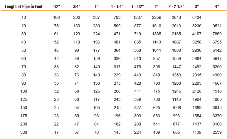
- Natural Gas (NG) flow is given in thousands of BTU/hr. = 1 cubic foot of NG gas – 1000 BTU
- Nominal pressure at the burner for Natural Gas is 3.5” of water column. (Typical machine supply 5”-7”)
- Pipe length must include additional length for all fittings.Add approximately 5 feet of pipe per fitting.
- Natural Gas Example: A machine with a burner that requires 440,000 BTU would need a 1 -1/4” pipe for a 20” long run.
LIQUID PROPANE : PIPE SIZING CHART
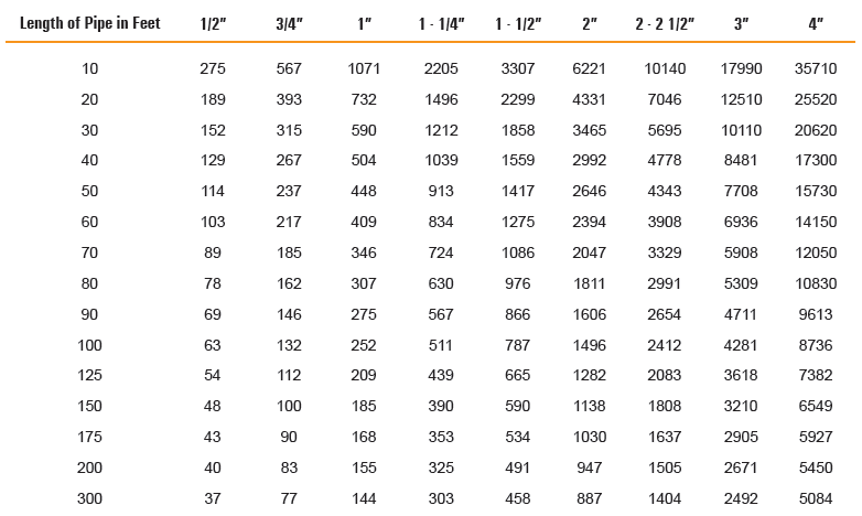
- Liquid Propane (LP) Gas flow is given in thousands of BTU/hr. = 1 cubic foot of LP gas – 2500 BTU.
- This chart refers to low pressure LP, after regulation, Standard nominal pressure at the burner for Liquid Propane Gas is 11” of water column.
- Pipe length must include additional length for all fittings. Add approximately 5 feet of pipe per fitting.
- LP Example: A machine with a burner that requires 440,000 BTU would need a 1” pipe for a 20’ long run.
NOTE: The sizing charts above list the specific pipe sizes required for the amount of BTU’s for a new gas line installations. If you are using an existing gas line you must take into consideration the existing gas line capacities to ensure you will have proper pressure. This chart is for reference only, we recommend you consult with a Licensed Plumber/Gas Fitter or NFPA54 (National Fuel Gas Code – current edition) for more details.
INSTALLATION REQUIREMENTS OF FIRE FEATURE
REQUIREMENTS
- This fire feature is permitted to be placed on a stable, flat combustible surface. The area underneath must be a solid level surface maintaining clearances according the specifications in this manual on page 4.
- Refer to the NFPA54 (National Fuel Gas Code) for proper pipe sizing. See Table 4 on page 6.
- Determine the model fire feature you are preparing to install (Refer to page 4).
- Follow the local code requirements for the gas type being used. This fire feature should be installed in accordance with local codes and ordinances or in the absence of local codes, with the latest National Fuel Gas Code, ANSI Z223.1 NFPA54 or CSA B149.1, Natural and Propane Installation Code in Canada.
- Fire features create high temperatures, it is very important to have any combustibles at a safe distance.
- NOTICE: Proper ventilation is built into the concrete fire feature. Do not bury or enclose or conceal thebottom of the fire feature into earth, other type media that could block ventilation necessary for this product.
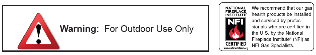
- These fire features are designed for outdoor use only. Not approved for any indoor use.
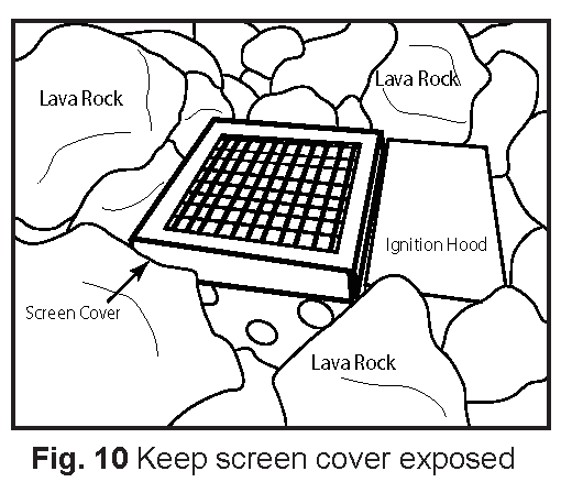
- This fire feature is designed to have lava rock completely covering the spur burner, so that the burner is not visible.Do not cover more than 1” above the top of the covered burner. When purchasing Lava Rock us minimum of 1 to 2-inch diameter as a base to fill the burner pan. DO NOT COVER THE IGNITION HOOD WITH ANY ROCK OR MEDIA.
- Gas lines and fittings must be installed in to the non-combustible structure. All gas connections must be leak tested before installation of the fire feature. Soapy water leak detection is required before regular use of the fire feature.
- Do not use material that will absorb moisture over time and will not release this moisture quickly. Moisture can boil in this material and can rapidly break apart and cause damage or personal injury.
- Never leave any other combustible material on top of the fire feature. This could cause unsafe operation of this system and damage to the component that will not be covered under our warranty.
SANCTUARY PREPARATION
Depending on the model you purchased, the installation will vary slightly. See pages 8-11 for your specific model. First mount the valve assembly (TMSI or MT) into the Sanctuary model as shown on page 8. Then proceed installing the burner pan assembly with the gas connections. Ensure there is enough “play” in the gas line to enable the burner to easily lift out for service if necessary.
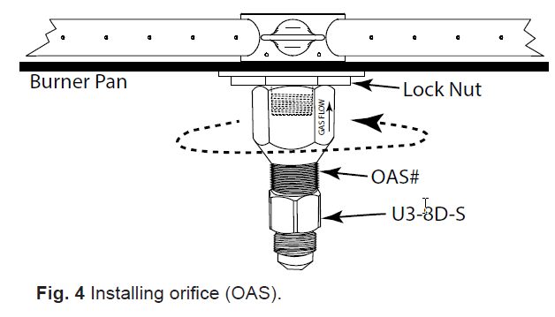
INSTALLING BURNER ORIFICE (OAS)Locate the burner nipple underneath the burner pan. Ensure the nipple from on the spur burner has gas rated Teflon tape wrapped around the threads. Thread the OAS (orifice air shutter) on to the nipple of the burning spur clockwise manner. Secure into position. See Fig. 4.
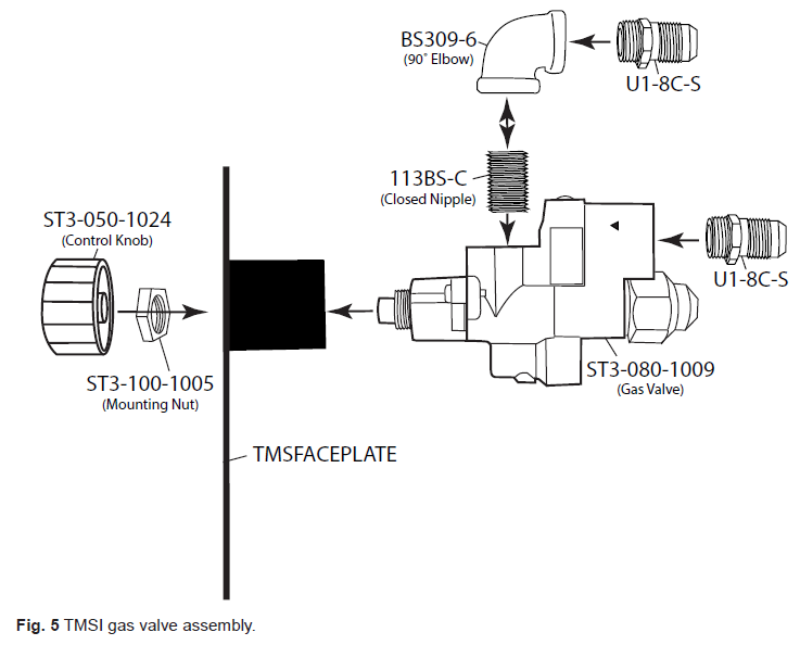
GAS VALVE ASSEMBLY (TMSI & MT)
Sanctuary fire feature the gas valve assembly comes assembled. The diagrams provide a reference for the specific parts.

TYPICAL INSTALLATION DRAWINGS
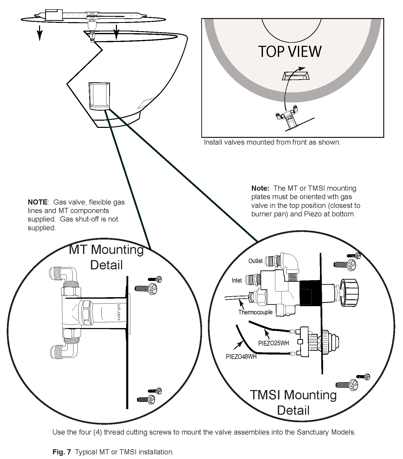
INSTALLATION OF TMSI SYSTEM
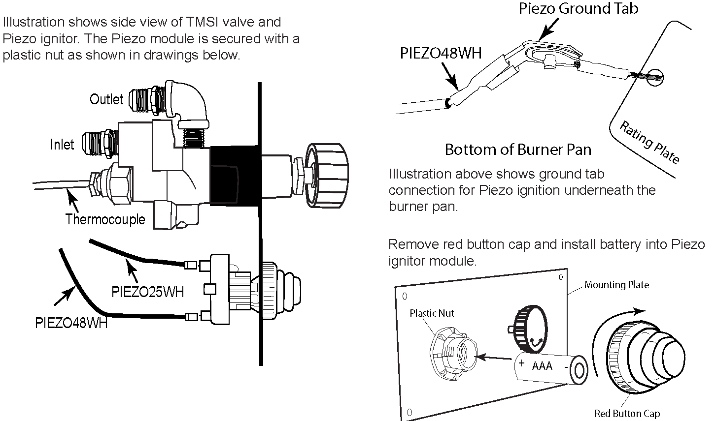
Illustration shows side view of TMSI valve and Piezo ignitor. The Piezo module is secured with a plastic nut as shown in drawings below.
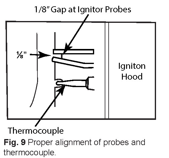
THERMOCOUPLE ALIGNMENTIt is important check the thermocouple to enure it is properly aligned overtop of the rainshield cutout area and that it did not move during shipping. Before lighting remove the screen cover of the ignition hood to burner and visually look at the thermocouple tip. The tip must be centered and protruding past the cutout area to ensure it remains hot during operation of your fire feature. Replace the screen cover and follow the operating instructions after inspection. See Fig. 9
Note: Ensure thermocouple wire and Piezo wires do not touch bottom of burner pan. Leave approximately 3-4 inches or more of air space from the burner pan.
INSTALLATION OF LAVA ROCK/MEDIA INTO BURNER PANInstall lava rock into the burner pan. Ensure the lava rock is a 1 to 2 inches indiameter for proper operation. Note: Do not pour Lava Rock directly from bag.It should be placed naturally and NOT packed in tight. Loose fitting is important to ensure robust flames. Be sure rocks are free of any excessive dust. This prevents the burner pan weep holes from being plugged and holding water.
IMPORTANT: Do not place rock over top or under the screen cover. The screen must be free of any debris to ensure proper lighting of burner (See Fig. 10). Cover the burner completely with media but do not make the depth greater than 1-inch overtop of the burner portholes. Do NOT cover the screen mesh with any rock or glass. It must be free an any debris to operate properly.
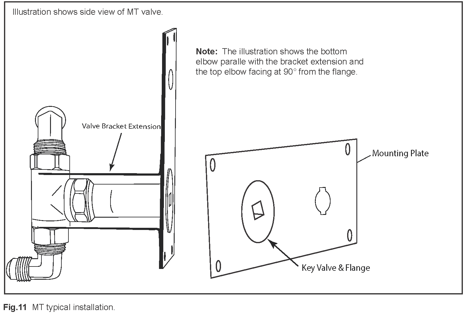
INSTALLATION OF MT SYSTEM
MEDIA SPECIFICATIONS
The Sanctuary 2 and 3 are only approved use with Lava Rock.
- Sanctuary 2 is approved with requires 57lbs of lava rock. Order (1) 50lb box and (1) 10lb. bag.
- Sanctuary 3 uses 24lbs of lava rock. Order (3) 10lb bags.
Lava rock height should be level and no higher than the top lip of the bowl (approximatley 2“ depth from burner pan).

TMSI OPERATION
CAUTION: Children and adults should be alerted to the hazards on high surface temperatures and should stay away to avoid burns or clothing ignition. Young children should be carefully supervised when they are in the area of the appliance.
WARNING: Do not use this appliance if any part has been under water. Immediately call a qualified service technician to inspect the appliance and to replace any part of control system and any gas control, which has been under water.
SAFETY WARNINGS
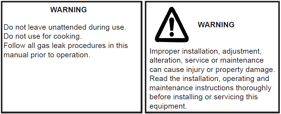
- Never leave the fire feature unattended during operation.
- Clothing or other flammable materials should not be placed on or near the appliance.
- Any guard or other protective device removed for servicing the appliance must be replaced prior to operating the appliance.
- Installation and repair should be done by a qualified service person. The appliance should be inspected beforeuse and at least annually by a qualified service person. More frequent cleaning may be required as necessary. Itis imperative the control compartment, burners and circulating air passageways of the appliance be kept clean.
- Inspect the fuel supply connection before each use of the appliance.
- Temporary storage of this appliance indoors is permissible only if it has been disconnected from its fuel supply (Natural or L.P. gas line).
WARNING
- This appliance is hot when operated and can cause sever burns if contacted.
- Do not burn any solid fuels in this appliance.
READ ALL LIGHTING INSTRUCTIONS BEFORE ATTEMPTING TO LIGHT FIRE FEATURE
CAUTION: ENSURE YOU HAVE LEAK TESTED THE FIRE FEATURE BEFORE OPERATING.WARNING: Do not stand over fire feature during ignition or operation due to high surface temperatures.
TMSI- LIGHTING INSTRUCTIONS
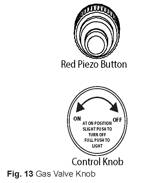
TURNING ON FIRE FEATURE
- Depress and hold the red Piezo ignitor button and ensure sparking is occurring at the probes inside ignition hood.
- Rotate control knob on gas valve counter clockwise to the ON position.
- Depress control knob inward to release gas and light the burner.
- After the fire feature lights release the Piezo button but continue to depress the control knob for at least 30 seconds then release knob. If fire feature does not light within 30 seconds, release control knob, turn knob clockwise to turn OFF and wait 5 minutes before trying again. Turn gas supply OFF to check probe spacing and Piezo battery if fire feature does not light.
- Repeat steps 1-4.
TURNING OFF FIRE FEATURE
- Slight push inward on control knob and turn clock wise until it stops. Fire feature will turn OFF.
- After cooling off install cover (if applicable).
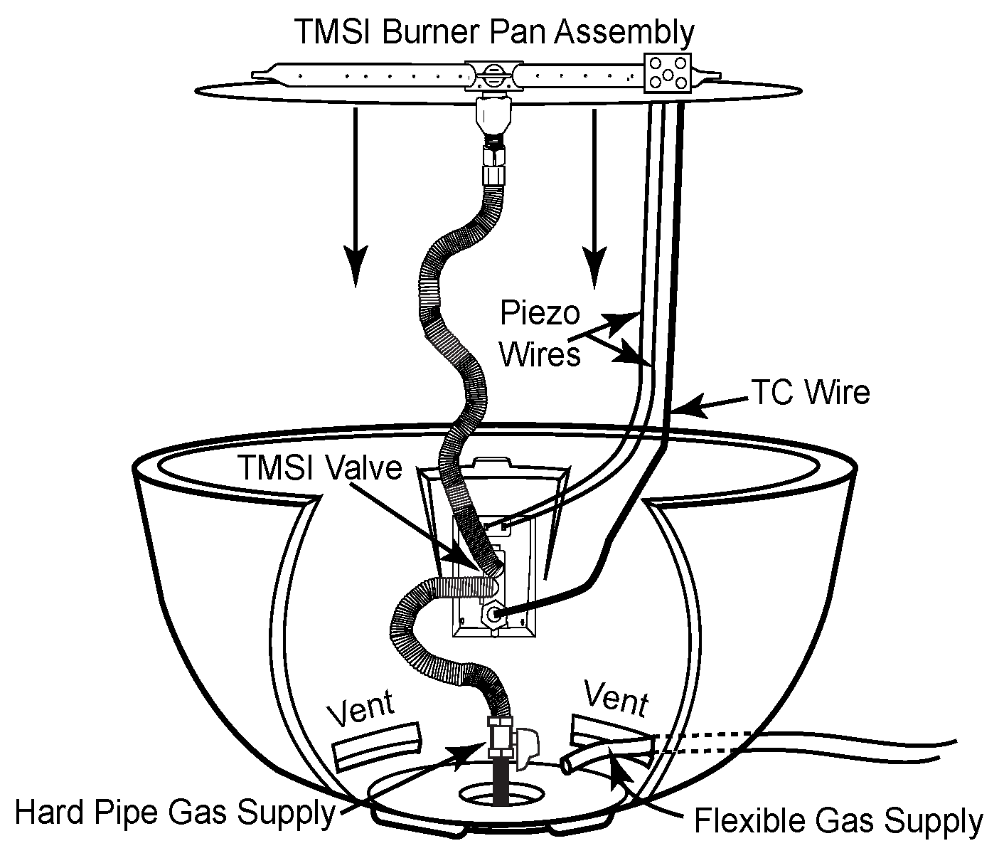
TMSI Expanded View In Sanctuary Bowl
Note: The gas supply may be hard piped into the center of the bowl or an approved flexible gas line can be installed through one of the lower vents.
MT OPERATION
CAUTION: Children and adults should be alerted to the hazards on high surface temperatures and should stay away to avoid burns or clothing ignition. Young children should be carefully supervised when they are in the area of the appliance.
WARNING: Do not use this appliance if any part has been under water. Immediately call a qualified service technician to inspect the appliance and to replace any part of control system and any gas control, which has been under water.
SAFETY WARNINGS
- Never leave the fire feature unattended during operation.
- Clothing or other flammable materials should not be placed on or near the appliance.
- Any guard or other protective device removed for servicing the appliance must be replaced prior to operating the appliance.
- Installation and repair should be done by a qualified service person. The appliance should be inspected beforeuse and at least annually by a qualified service person. More frequent cleaning may be required as necessary. Itis imperative the control compartment, burners and circulating air passageways of the appliance be kept clean.
- Inspect the fuel supply connection before each use of the appliance.
- Temporary storage of this appliance indoors is permissible only if it has been disconnected from its fuel supply (Natural or L.P. gas line).
WARNING
- This appliance is hot when operated and can cause sever burns if contacted.
- Do not burn any solid fuels in this appliance.
READ ALL LIGHTING INSTRUCTIONS BEFORE ATTEMPTING TO LIGHT FIRE FEATURECAUTION: ENSURE YOU HAVE LEAK TESTED THE FIRE FEATURE BEFORE OPERATING.
WARNING: Do not stand over fire feature during ignition or operation due to high surface temperatures.
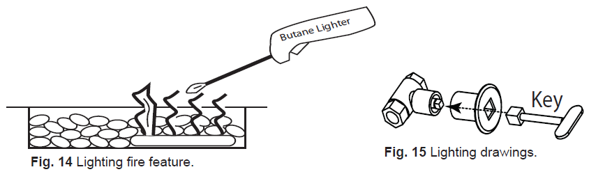
MT- LIGHTING INSTRUCTIONS
TURNING ON SANCTUARY FIRE FEATURE
- Light a Butane lighter inside edge of the Sanctuary fire feature over an end of the burner tube area.
- Turn ON gas supply at the manual key valve.
- Gas should ignite within 10 seconds or less. If fire feature does not light within 30 seconds, turn key clockwise to turn OFF and wait 5 minutes before trying again. Turn gas supply OFF to check and check main gas supply to ensure it was turned ON.
- Repeat steps 1-4.
TURNING OFF SANCTUARY FIRE FEATURE
- Insert key and turn clockwise until key stops. Fire feature will stop.
- After cooling off install cover to protect the Sanctuary Fire Feature (if applicable).
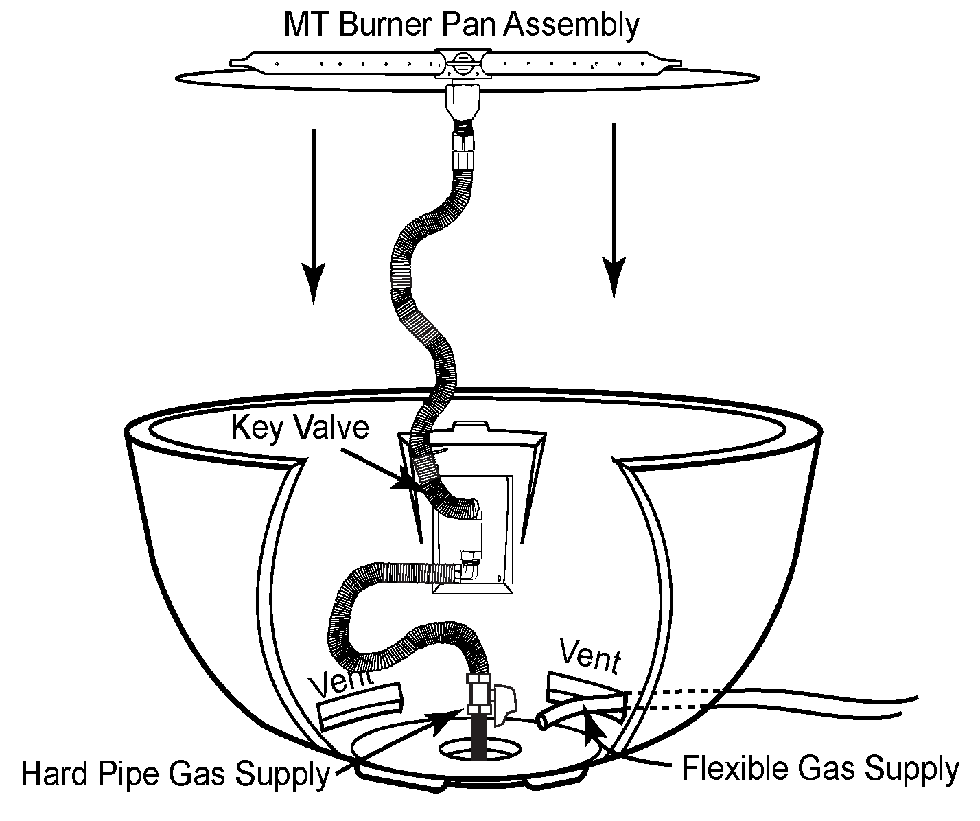
MT Expanded View In Sanctuary Bowl
Note: The gas supply may be hard piped into the center of the bowl or an approved flexible gas line can be installed through one of the lower vents.
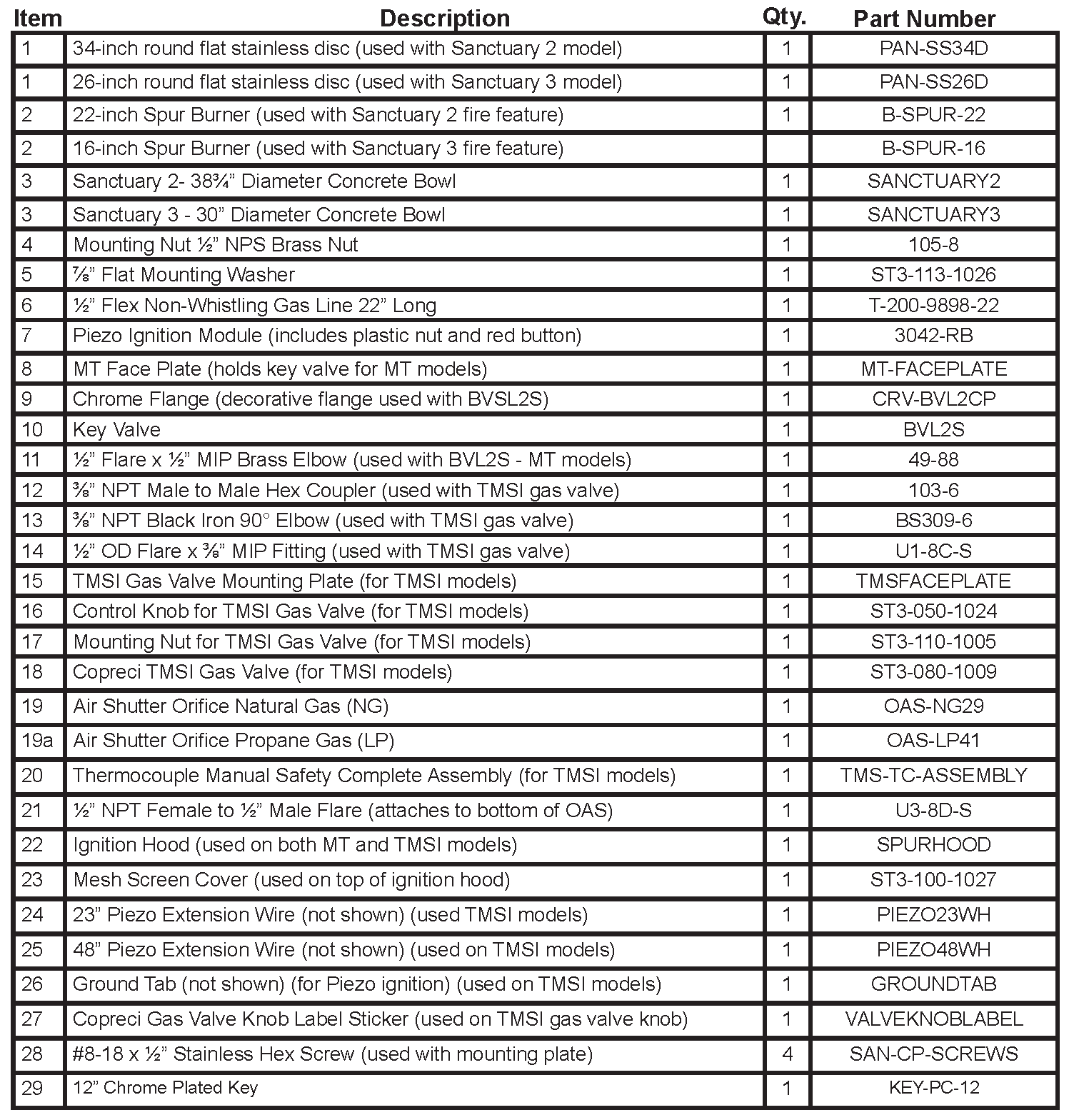
SANCTUARY 2 & 3 REPLACEMENT PARTS

SANCTUARY 2 & 3 REPLACEMENT PARTS LIST
FIRE FEATURE MAINTENANCE
- These fire features should be inspected and cleaned before initial use at least annually by a qualified field service person.
- Any component that is found faulty must be replaced with an approved component.
- Any tampering or modifying with the fire feature is dangerous and voids all warranties.
- During winter months in cold climates and various seasons operation the fire feature may be affected by weather conditions. It is recommended to use a cover/lid overtop of your fire feature to protect it from humid/rainy weather conditions when not in use. Heavy rains/downpours could affect the fire feature operation if not covered; if this occurs ensure you allow the fire feature time to dry out before attempting to operate. NOTE: If a combustible type cover is used over the fire feature when not in use be sure to remove it before operation to prevent a severe safety hazard.
- Carbon (soot) may build up on the surface of logs (if installed) during heavy use. Sooting may also occur periodically on the screen of the ignitor hood. To clean, brush off with a dry bristle brush or cloth. Keep soot away from clothing or furniture.
- Over time stainless steel parts can discolor when heated, usually a golden or brown hue. This discoloration is normal and does not affect the performance of the appliance.
GFRC MAINTENANCE
- To care for your GFRC (Glass Fiber Reinforced Concrete) product, please utilize careful judgment. It is a durable and forgiving material, but that does not mean you can expose it to harsh chemicals or mechanical cleaning methods which could damage the outer finish. Instead, we recommend you use a soft brush with natural or synthetic bristles, utilizing very light pressure and water to clean the concrete items.
- Concrete by nature, is a porous material and therefore, susceptible to staining. In addition, over time it will age sometimes changing the color just as the common household driveway will. Sealing of products is always recommended to protect the original appearance. Our products are sealed prior to shipment but the continued care and resealing of the product will be needed every 4-5 years to protect the appearance.
- With a concrete sealant, your concrete will look great and natural for many occasions. Prolonged contact with overly acidic, heavily pigmented or alkali substances should be avoided. We recommend cleaning any spills as quickly as possible. Take caution against use of caustic acids to clean or resurface concrete products. Such caustic acids have historically been used to clean pools, sidewalks or other porous concrete surfaces. These acids will etch the surface and change the structure of the concrete at the surface level. Our concrete is made to have a denser and cleaner look; such etching from caustic acids will change that clean, smooth finish.
- DO NOT USE HARSH ABRASIVE CLEANERS, ACIDS, PIGMENTED CLEANERS OF ALKALI SUBSTANCES ON CONCRETE PRODUCTS. While for many applications it MAY be safe to use muriatic acid/hydrochloric acid or sulfuric acid, or other strong chemicals to clean concrete, DO NOT use these cleaners to clean the items we sell made from reinforced concrete. This WILL damage the beautiful finish on the outside of the concrete. Such chemical cleaners are not applicable for use on this type of material.
- Additionally, we do not recommend using high-pressure cleaning, as this could remove the sealed finish. Using a garden hose will be enough pressure to clean the concrete. For normal spills, a quick wipe up and gentle “scrub” with a cotton cloth or similar, should be enough to clean. For stains, which contain dark colors or have been sitting for an extended period of time, you can use a mild soap. Under extreme cleaning needs, you can use a standard mild household chlorine bleach, available in most retail stores, diluted to a very weak mixture of about 1/4 cup bleach to 1 gallon of water. Use this mixture over the entire surface you wish to clean, to ensure even cleaning. Only do this as a last resort as it could change the appearance of the product.
- Please also note that fissures (hairline cracks) can appear on the surface due to age and/or exposure to theatmospheric conditions. These commonly don’t have an effect on durability and do not compromise the structural integrity of the product.
TROUBLE SHOOTING

LIMITED WARRANTY
Skytech Products Group (Firegear Outdoors) hereby warrants to the end user that products will be free from material and workmanship defects that prevent safe and correct operation of the product. The warranty commences from date of sale to the end user for the following period:
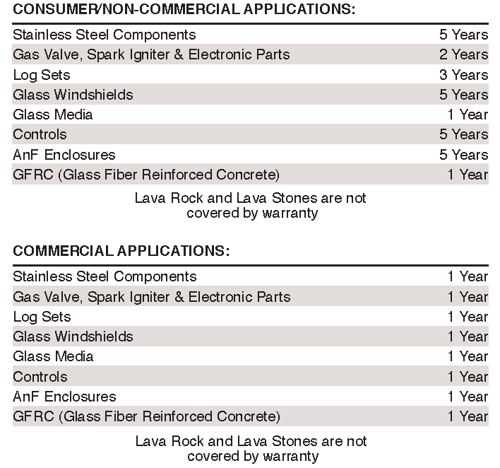
End User must provide a bill of sale, canceled check, or payment record from the end user to verify purchase date and to establish warranty period. This Limited Warranty shall be valid and limited to the original purchaser only.
WARNING Any modification to the product will void the warranty.This Limited Warranty shall be limited to the repair and/or replacement of parts that have proven to be defective under normal use and service. Before returning any parts, contact our Technical Service Department for a Return Materials Authorization (RMA) number. All warranty claims must be made by the OEM / Distributor / Dealer account on behalf of the end user. You may contact Technical Service at (855) 498-8324.All approved returned defects must be confirmed by our Technical Service Department. If the defect is confirmed and we approve the claim, we will replace such parts without charge.This warranty gives you specific legal rights, and you may also have other rights, which vary from state to state.
Travel, diagnostic cost, service labor to repair the defect and freight charges on warranty parts to and from the factory will be responsibility of the owner. We will not be responsible for labor charges and/or damage incurred in installation, repair, and replacement.
This Limited Warranty is voided if not assembled, installed and operated as intended. This Limited Warranty does not cover any defects due to accident, abuse, misuse, alteration, misapplication, vandalism, improper installation or improper maintenance or service, removal from the original location or re- installation into another location, or failure to perform normal and routine maintenance.
Damage due to severe weather conditions such as hail, hurricanes, earthquakes, tornadoes, discoloration due to overheating, exposure to chemicals (including salt), either directly or in the atmosphere, or very high humidity, is not covered by this Limited Warranty.
There are no other express warranties except as set forth herein.For consumer applications, any applicable implied warranties of merchantability and fitness are limited induration to the period of coverage of this Limited Warranty. Some states do not allow limitation on how long an implied warranty lasts, so this limitation may not apply to you.
For Commercial applications, the liability of Firegear Outdoors is limited to the express terms of this warranty. We expressly disclaim any and all implied warranties, including any warranties of fitness for a particular purpose or merchantability.
We are not liable for any special, indirect or consequential damages. Our maximum liability is limited to the purchase price of the purchased products. Some states do not allow the exclusion or limitation of incidental or consequential damages, so this limitation or exclusions may not apply to you.
We do not authorize any person or company to assume for it any other obligation or liability in connection with the sale, installation, use, removal, return, or replacement of its equipment; and no such representations are binding.
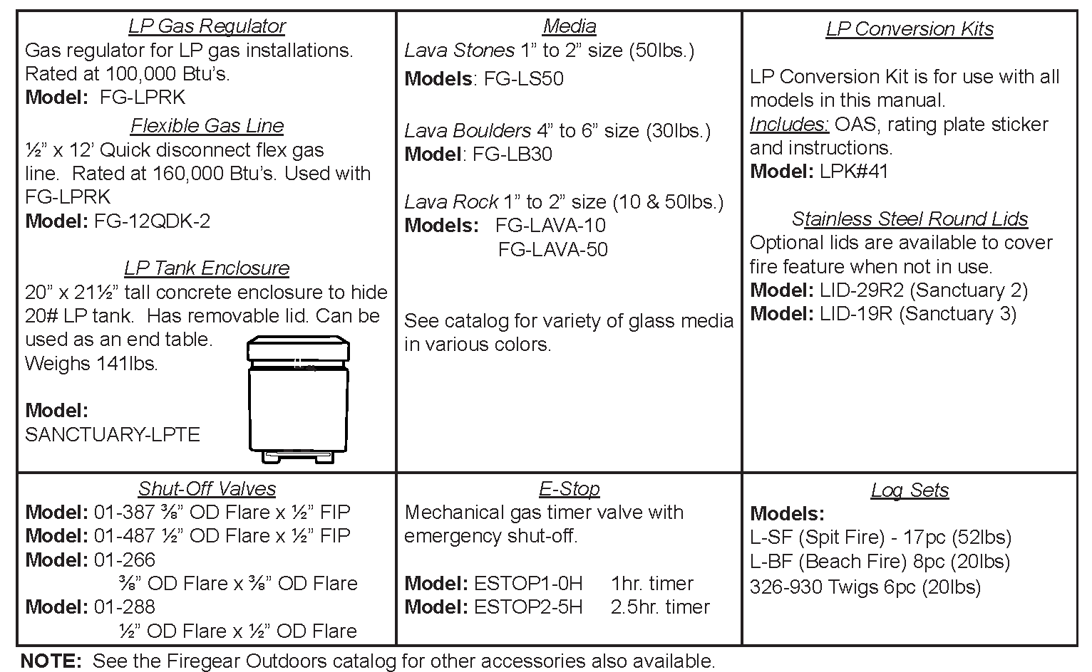
OPTIONAL ACCESSORIES
The following accessories are available from your local Firegear dealer/distributor.Each accessory comes with a separate installation manual. Read each instruction thoroughly before installing.
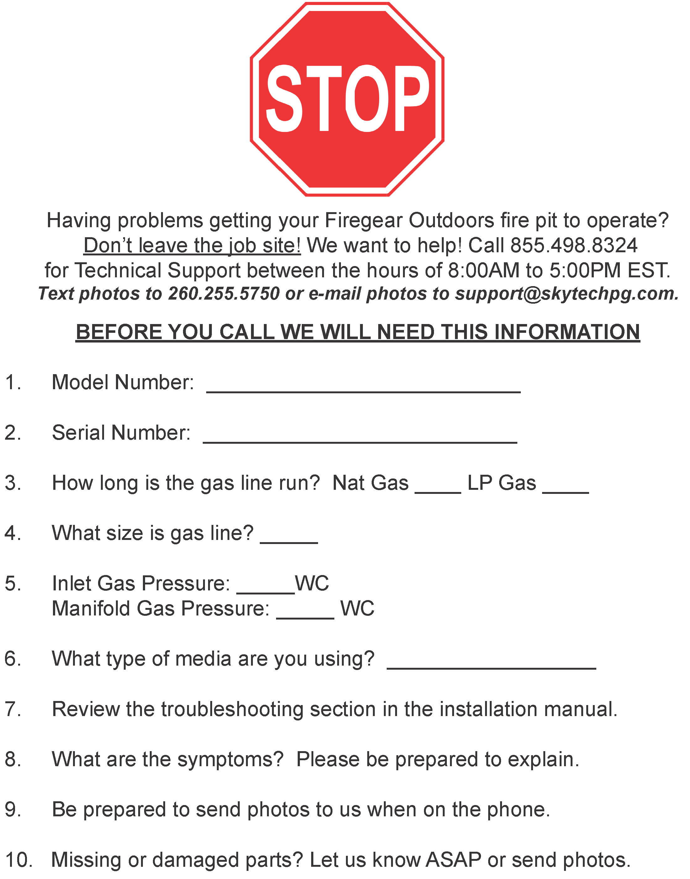
FOR TECHNICAL SERVICE, CALL: (855) 498-8324
Firegear Outdoors9230 Conservation WayFort Wayne, IN 46809Sales: (888) 672-8929Sales Support: (888) 699-6167Canadian Inquires: (877) 472-3923Web Site: www.firegearoutdoors.com
![]()
References
[xyz-ips snippet=”download-snippet”]