FLUKE Hart Scientific Thermo
Hygrometer User Guide

Limited Warranty & Limitation of Liability
Each product from Fluke Corporation, Hart Scientific Division (“Hart”) is warranted to be free from defects in material and workmanship under normal use and service. The warranty period is one year for the Thermo-Hygrometer. The warranty period begins on the date of the shipment. Parts, product repairs, and services are warranted for 90 days. The warranty extends only to the original buyer or end-user customer of a Hart authorized reseller, and does not apply to fuses, disposable batteries or to any other product, which in Hart’s opinion, has been misused, altered, neglected, or damaged by accident or abnormal conditions of operation or handling. Hart warrants that software will operate substantially in accordance with its functional specifications for 90 days and that it has been properly recorded on non-defective media. Hart does not warrant that software will be error free or operate without interruption. Hart does not warrant calibrations on the Thermo-Hygrometer.
Hart authorized resellers shall extend this warranty on new and unused products to end-user customers only but have no authority to extend a greater or different warranty on behalf of Hart. Warranty support is available if product is purchased through a Hart authorized sales outlet or Buyer has paid the applicable international price. Hart reserves the right to invoice Buyer for importation costs of repairs/replacement parts when product purchased in one country is submitted for repair in another country. Hart’s warranty obligation is limited, at Hart’s option, to refund of the purchase price, free of charge repair, or replacement of a defective product which is returned to a Hart authorized service center within the warranty period.
To obtain warranty service, contact your nearest Hart authorized service center or send the product, with a description of the difficulty, postage, and insurance prepaid (FOB Destination), to the nearest Hart authorized service center. Hart assumes no risk for damage in transit. Following warranty repair, the product will be returned to Buyer, transportation prepaid (FOB Destination). If Hart determines that the failure was caused by misuse, alteration, accident or abnormal condition or operation or handling, Hart will provide an estimate or repair costs and obtain authorization before commencing the work. Following repair, the product will be returned to the Buyer transportation prepaid and the Buyer will be billed for the repair and return transportation charges (FOB Shipping Point).
THIS WARRANTY IS BUYER’S SOLE AND EXCLUSIVE REMEDY AND IS IN LIEU OF ALL OTHER WARRANTIES, EXPRESS OR IMPLIED, INCLUDING BUT NOT LIMITED TO ANY IMPLIED WARRANTY OF MERCHANTABILITY OR FITNESS FOR A PARTICULAR PURPOSE. HART SHALL NOT BE LIABLE FOR ANY SPECIAL, INDIRECT, INCIDENTAL. OR CONSEQUENTIAL DAMAGES OR LOSSES, INCLUDING LOSS OF DATA, WHETHER ARISING FROM BREACH OF WARRANTY OR BASED ON CONTRACT, TORT, RELIANCE OR ANY OTHER THEORY.
Since some countries or states do not allow limitation of the term of an implied warranty, or exclusion or limitation of incidental or consequential damages, the limitations and exclusions of this warranty may not apply to every buyer. If any provision of this Warranty is held invalid or unenforceable by a court of competent jurisdiction, such holding will not affect the validity or enforceability of any other provision.
Before You Start
Introduction
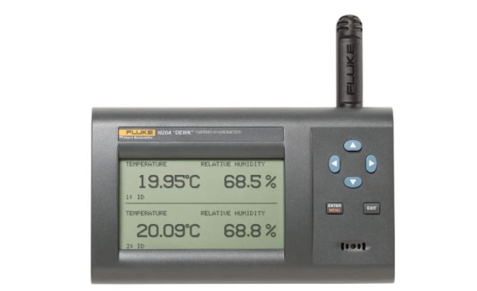
Fluke’s Hart Scientific Division’s 1620A is a low-cost, high-accuracy, digital thermo-hygrometer. Its unique combination of features makes it suitable for a wide variety of applications from laboratory to industrial ambient measurement. Features of the thermo-hygrometer include:
- Two channels measure ambient temperature to ± 0.125 °C and %RH to ± 1.5 %
- Two sensor capability (second sensor optional), each measuring temperature and relative humidity; each is detachable, cable-extendable, and interchangeable, with self-contained calibration; each may be assigned a unique 16-character identification
- Display resolution is user selectable up to 0.001 °C and 0.01% RH
- On-board memory holds up to 400,000 time/date-stamped readings
- Serial RS-232 interface for reading measurements and access to settings
- Ethernet LAN interface provides TCP/IP communicatins and embedded HTML web page for reading measurements over a network
- Optional wireless RF 802.15.4 (ZigBee) for remote operation
- Visual and audio alarms for various alarm or fault conditions, alarm output port
- May be wall mounted or set on a bench top
- Detachable sensors contain their own calibration data for easy recalibrations
- Optional software logs in real-time or shows graphical/statistical data
- Password protection of settings
- Large LCD displays temperature and humidity data graphically, numerically, and statistically; 16 pre-defined, user-changeable screen setups
- Power 12 V dc from external 110-240 V ac to dc converter
- Uses a standard 9V battery backup to allow continued measuring during power interruptions
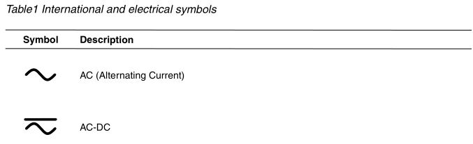
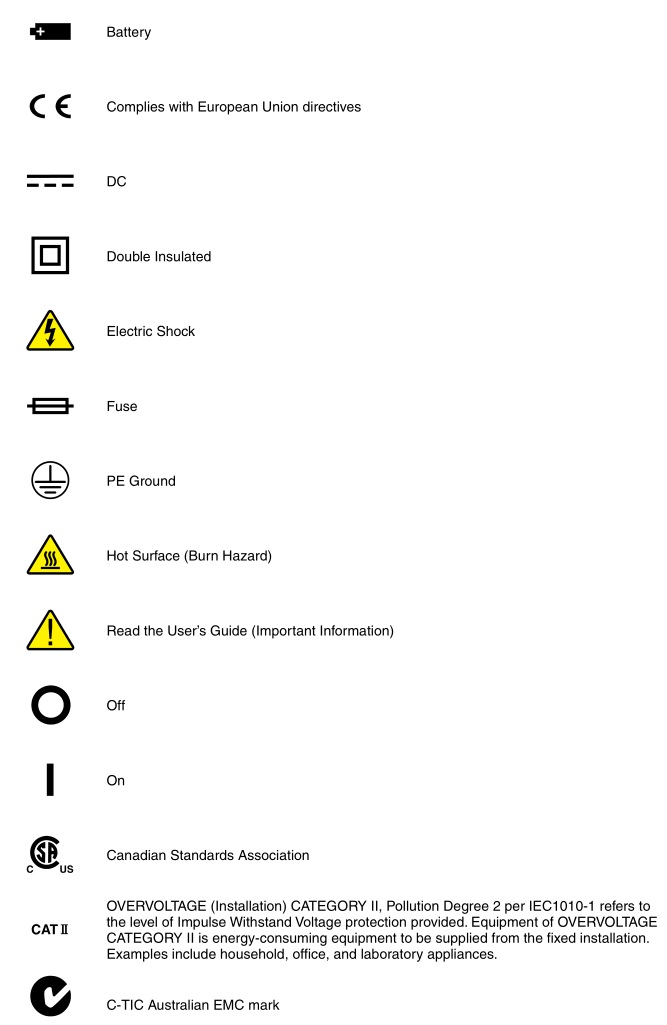
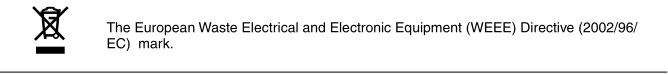
Symbols Used
Table 1 lists the International Electrical Symbols. Some or all of these symbols may be used on the instrument or in this manual.
Safety Information
Use this instrument only as specified in this manual. Otherwise, the protection provided by the instrument may be impaired.
The following definitions apply to the terms “WARNING” and “CAUTION”.
“WARNING” identifies conditions and actions that may pose hazards to the user.
“CAUTION” identifies conditions and actions that may damage the instrument being used.
WARNINGS
To avoid personal injury, follow these guidelines.
- DO NOT use this unit in environments other than those listed in the User’s Guide.
- Follow all safety guidelines listed in the User’s Guide.
- Calibration equipment should only be used by trained personnel.
- The AC adapter can present safety concerns if misused or damaged. To avoid the risk of electric shock or fire, do not use the AC adapter outdoors or in a dusty, dirty, or wet environment. If the cord, case, or plug of the adapter is damaged in any way, discontinue its use immediately and have it replaced.
- Never disassemble the AC adapter. Use only the AC adapter provided with the instrument or equivalent adapter recommended by the manufacturer of this instrument.
- The AC adapter has circuits with high voltage inside that could present danger of electrical shock or fire if exposed. If the AC adapter is damaged in any way or becomes hot, discontinue its use immediately, disconnect it from any AC supply, and have it replaced. Do not attempt to open, repair, or continue using a damaged or defective AC adapter.
- The instrument battery can present danger if not handled properly. To avoid the risk of exposure to dangerous substances or explosion, immediately remove the battery and discontinue use if it leaks or becomes damaged. Never allow the battery to be shorted, heated, punctured, or dropped. If the instrument is physically damaged, immediately remove the battery to insure that it does not become shorted. While removed from the instrument, store the battery in a location so that it will not come into contact with metal or fluids that might short circuit the battery and where it is safe from excessive temperatures.
- Used batteries must be disposed of properly. Check your local regulations for additional information. Never dispose of batteries in fire which may result in explosion with the possibility of personal injury or property damage.
CAUTIONS
- If the instrument is dropped, struck, or handled in a way that causes internal or external physical damage, immediately unplug the AC adapter, remove the battery, discontinue use, and contact an Authorized Service Center. Do not attempt to disassemble or repair the instrument, battery, or AC adapter. Refer repairs or replacement components to an Authorized Service Center.
- The instrument and sensors are sensitive and can be easily damaged. Always handle these devices with care. DO NOT allow them to be dropped, struck, stressed, or overheated.
- Sensors are fragile devices which can be damaged by mechanical shock, overheating, and exposure to fluids. Damage may not be visibly apparent but can cause drift, instability, and loss of accuracy. Observe the following precautions:
- DO NOT allow sensors to be dropped, struck, or stressed.
- DO NOT overheat sensors beyond their recommended temperature range.
- Keep the sensors clean and away from fluids and dust.
Please contact one of the following authorized Service Centers to coordinate service on your Hart product:
Fluke Corporation, Hart Scientific Division799 E. Utah Valley DriveAmerican Fork, UT 84003-9775USAPhone: +1.801.763.1600Telefax: +1.801.763.1010E-mail: [email protected]
Fluke Nederland B.V.Customer Support ServicesScience Park Eindhoven 51085692 EC SonNETHERLANDSPhone: +31-402-675300Telefax: +31-402-675321E-mail: [email protected]
Fluke Int’l CorporationService Center – InstrimpexRoom 2301 Sciteck Tower22 Jianguomenwai DajieChao Yang DistrictBeijing 100004, PRCCHINAPhone: +86-10-6-512-3436Telefax: +86-10-6-512-3437E-mail: [email protected]
Fluke South East Asia Pte Ltd.Fluke ASEAN Regional OfficeService Center60 Alexandra Terrace #03-16The Comtech (Lobby D)118502SINGAPOREPhone: +65 6799-5588Telefax: +65 6799-5588E-mail: [email protected]
When contacting these Service Centers for support, please have the following information available:
- Model Number
- Serial Number
- Voltage
- Complete description of the problem
Specifications and Environmental Conditions
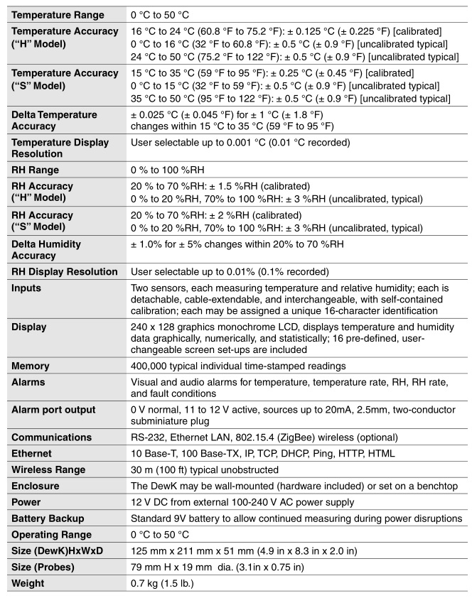
Specifications
Environmental Conditions
Although the instrument has been designed for optimum durability and trouble-free operation, it must be handled with care. The instrument should not be operated in an excessively dusty, dirty, or wet environment. Maintenance and cleaning recommendations can be found in the Maintenance section of the User’s Guide. For full accuracy, operate the instrument within the calibrated temperature and relative humidity range of the sensors.
1620A DewK
- Operating Temperature: 0 °C to 50 °C (32 °F to 122 °F)
- Relative Humidity: 0% to 70 %RH
2626-H/S
- Operating Temperature: 0 °C to 50 °C (32 °F to 122 °F)
- Relative Humidity: 0% to 100 %RH
AC Adapter
- Operating Temperature: 0 °C to 40 °C (32 °F to 104 °F)
- Relative Humidity: 5% to 90% non-condensing de-rating from 40 °C linearly to 50% at 70 °C
General to all
- Pressure: 75 kPa-106 kPa
- Vibration should be minimized
- Altitude less than 2,000 meters
- Indoor use only
Quick Start
This section briefly explains the basics of setting up and operating your thermo-hygrometer.
Unpacking
Carefully unpack the thermo-hygrometer and inspect the instrument to make sure all components are present and in satisfactory condition. Verify that the following items are present:
- 1620A Thermo-Hygrometer
- AC adapter and power cord
- Serial cable Manual Report of calibration Wall mount bracket Sensor 9V battery
If all items are not present, contact an Authorized Service Center.
Use Proper Care
First and most important is to understand the safety issues related to the thermo-hygrometer. Carefully read the Safety Information section at the beginning of this guide.
The thermo-hygrometer and sensors used with it are sensitive instruments that can be easily damaged. Always handle these devices with care. DO NOT allow them to be dropped, struck, stressed, or over-heated.
Learn About the Features and Components
Familiarize yourself with the features and accessories of the thermo-hygrometer by reading the Parts and Controls section of this guide.
Install the Battery
To maintain uninterrupted measurement when power outages occur, you must install the included battery into the rear battery compartment. A standard 9V alkaline battery (NEDA 1604A or IEC 6LR61) is recommended. With a fresh alkaline battery installed, the thermo-hygrometer will continue to measure and record temperature and relative humidity during a power outage for up to 16 hours, typically. However, without external power, the display will be inoperable.
Connect the Sensor
The sensor for channel 1 connects to the socket at the top-right, and the sensor for channel 2, if used, connects to the socket on the right side. Either sensor may be used with an optional extension cable up to 100 feet (30 meters) in length.
Connect the Power Source
The thermo-hygrometer draws power from the provided power adapter. Plug the adapter into a wall outlet of the appropriate voltage and insert the DC plug into the DC power input of the thermo-hygrometer.
Switch the Power On
Power is turned on and off with the power switch located below the stand on the back panel. To switch the power on, toggle the power switch to the ‘I‘ position. To switch power off, toggle the power switch to the ‘O‘ position. The instrument takes a few seconds to power up, initialize, and begin normal operation. A self-test is performed, displaying the channel configuration and status of the system, calibration, % battery power, memory, and buttons. If the thermo-hygrometer calibration has expired and the alert message is enabled, the user is notified and must press the Enter button to continue initialization. If an error message is displayed on power up see the Troubleshooting section in the User’s Guide.
Measure Temperature
After initialization, the temperature and relative humidity measurements for the enabled channels are displayed. If recording is enabled, the measurements will be automatically stored in memory. The display can be configured to display the measurements in a variety of numerical and graphical formats. For information on the various modes of operation of the thermo-hygrometer, see the Menu Functions section of the User’s Guide.
Parts and Controls
The functions of the various features of the thermo-hygrometer are described below.
Front Panel
The front panel buttons ENTER/MENU, Up/Down/Left/Right Arrows, and EXIT are used to select and alter the functions of the thermo-hygrometer (see Figure 1).

The buttons have different functions depending on whether the main screen or the menu system is displayed.
The functions of each of the buttons from the main screen are as follows:
ENTER/MENU – This button is used to display the menu options.
EXIT – This button is used to display the alarm window. With the alarm window displayed the Exit button can be used to return to the main screen while preserving the alarm events or the Enter button can be used to clear the alarm events and return to the main screen.
◄▶ – These buttons are used to move among enabled display layouts.
▲▼ – These buttons are used to adjust the display contrast, ▲ for darker and ▼ for lighter. The functions of each of the buttons within the menu system are as follows:
ENTER/MENU – This button is used to select a menu item, to accept a choice, or save changes to a parameter.
EXIT – This button is used to return from a menu or window or cancel changes to a parameter. Pressing the Exit button for a second or so returns from most any menu, menu function, or window back to the main screen.
▲▼ – These buttons are used to move among menu items or parameters. When editing some numeric or alpha-numeric parameters, these buttons are used to change a digit or character.
◄▶ – These buttons are used to change a value or option when editing a parameter. When editing some numeric or alpha-numeric parameters, these buttons are used to move among digits or characters.
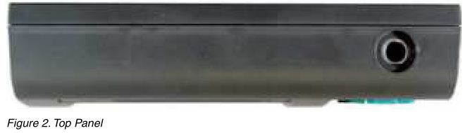
Top Panel
The top panel contains the port for attaching the sensor for Channel 1. An optional extension cable may be used to allow the sensor to be placed in a remote location.
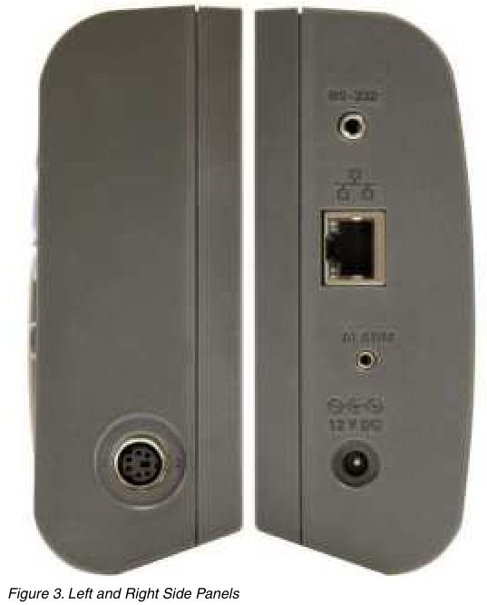
Right Side Panel
The right side panel contains the port for attaching the sensor for Channel 2. An optional extension cable may be used to allow the sensor to be placed in a remote location.
Left Side Panel
The left side panel consists of, from top to bottom, the RS-232 port, Ethernet LAN port, alarm port, and DC power socket.
RS-232 Port – The RS-232 port can be used to connect the instrument to a computer and remotely control and retrieve data from the instrument using a serial RS-232 interface. The jack accepts a 3.5 mm miniature stereo plug.
LAN Port – This RJ45 socket allows the instrument to be connected to an Ethernet IP computer network to remotely control and retrieve data from the instrument. The port has two LED indicators. The bottom LED indicates link state: off for no connection, amber for 10 Mbps, and green for 100 Mbps. The top LED indicates link activity: off for no activity, amber for half duplex, and green for full duplex.
Alarm Port – The alarm port allows external alarm indicators to be connected to the instrument and activated when an alarm event occurs. The port outputs 0V when inactive and 12V DC (up to 20 mA) when active. The jack accepts a 2.5 mm two-conductor subminature plug (Switchcraft #850). The sleeve of the plug is ground and the tip is positive.
DC Power Socket – The DC plug from the AC adapter plugs into the 12V DC power socket to power the instrument. The jack accepts a 5.5 mm miniature power plug (Switchcraft #S760). The outer conductor is ground and the inner conductor is positive. The instrument may draw up to 0.5A.
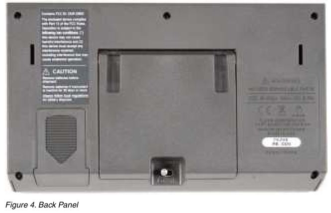
Back Panel
The back panel contains the stand, power switch, battery compartment, and product information, including serial number.
Stand – The stand can be used to prop up the thermo-hygrometer on a flat surface.
Battery Compartment – The battery compartment holds a 9V alkaline battery used as a backup power source to maintain continuous measurement during a power outage.
Power Switch – The power switch turns the power on and off to the thermo-hygrometer, including power from the battery. Before disconnecting the AC adapter from the instrument, switch the power off to prevent draining the backup battery.
Serial Label – The serial label shows the instrument model and serial number.
When the main screen is displayed, the buttons have the following functions:
ENTER/MENU – This button is used to display the menu options.
EXIT – This button is used to display the alarm window. With the alarm window displayed the Exit button can be used to return to the main screen while preserving the alarm events or the Enter button can be used to clear the alarm events and return to the main screen.
◄▶ – These buttons are used to move among enabled display layouts.
▲▼ – These buttons are used to adjust the display contrast, ▲ for darker and ▼ for lighter.
Configurations
- Model 1620A-H includes a 1620A Thermo-Hygrometer readout, a high accuracy sensor (Model 2626-H), a thermo-hygrometer readout wall mount bracket, power supply (Model 2361), and an RS-232 cable.
- Model 1620A-S includes a 1620A Thermo-Hygrometer readout, a standard accuracy sensor (Model 2626-S), a thermo-hygrometer readout wall mount bracket, power supply (Model 2361), and an RS-232 cable.
Accessories
The following accessories are available to compliment either the high accuracy or standard thermo-hygrometer readout.
- 2626-S Spare Sensor/Standard Accuracy
- 2627-S Spare Sensor Kit includes a standard accuracy probe (2626-S), sensor case(2607), sensor wall mount bracket (2630), and 25-foot (7.6 m) extension cable (2628)
- 2626-H Spare Sensor/High Accuracy
- 2627-H Spare sensor Kit includes a high accuracy sensor (2626-H), sensor case (2607), sensor wall mount bracket (2630), and 25-foot (7.6 m) extension cable (2628)
- 2607 Spare Sensor Protective Case
- 2628 Extension cable, 7.6 m (25 ft)
- 2629 Extension cable, 15.2 m (50 ft)
- 2630 Sensor wall mount bracket
- 9328 Protective Case (includes space for a 1620A Thermo-Hygrometer, two sensors, RS-232 cable, and power cord)
- 2361 Spare Power Supply, 100-240 V ac to 12 V dc
- 9936A LogWare III, single-PC license
- 9936A-L1 License, LogWare III, 1-pack
- 9936A-L5 License, LogWare III, 5-pack
- 9936A-L10 License, LogWare III, 10-pack
- 9936A-LST License, LogWare III, site
- 9936A-UPG Software,
- 9936A Upgrade from v1.X
- 2633-RF Option, Factory Installed Wireless, Dewk (Model 2633-USB or Model 2633-232 receiver required to communicate with this option)
- 2633-USB Wireless Modem, USB to wireless (requires 2633-RF)
- 2633-232 Wireless Modem, RS-232 to wireless (requires 2633-RF)
General Operation
This section explains basic operation of the thermo-hygrometer. Detailed operation of the thermo-hygrometer is explained in Sections 7 and 8 of the User’s Guide. Section 7 explains the menu structure and the functions available in the menu structure and Section 8 explains the communications interface for operating the thermo-hygrometer remotely.
DC Power Source
The thermo-hygrometer requires 12 V dc to operate. The ac adapter is provided to produce the DC power from an AC mains supply.
![]() CAUTION: For CE compliance and for proper performance, use only the AC adapter shipped with the instrument by Hart Scientific. If the AC adapter needs to be replaced, contact Hart Scientific Authorized Service Center. The AC adapter has circuits with high voltages inside that could present danger of electric shock or fire if exposed. If the AC adapter is damaged in any way or becomes hot, discontinue use immediately, disconnect the adapter from any AC supply, and replace the adapter. Do not attempt to open, repair, or continue using a damaged or defective AC adapter.
CAUTION: For CE compliance and for proper performance, use only the AC adapter shipped with the instrument by Hart Scientific. If the AC adapter needs to be replaced, contact Hart Scientific Authorized Service Center. The AC adapter has circuits with high voltages inside that could present danger of electric shock or fire if exposed. If the AC adapter is damaged in any way or becomes hot, discontinue use immediately, disconnect the adapter from any AC supply, and replace the adapter. Do not attempt to open, repair, or continue using a damaged or defective AC adapter.
The DC output from the AC adapter plugs into the 12 V dc power input on the left side of the instrument (see Figure 3 on page 13).
Battery
The thermo-hygrometer uses a 9 V battery to maintain continuous measurement and recording during power outages. The recommended battery type is a standard 9 V alkaline battery (NEDA 1604A or IEC 6LR61). During a power outage, or when the ac adapter is disconnected, the display will be inoperable but measuring will continue if the 9 V battery is installed. If the alarm is enabled, the beeper will sound periodically to alert the user of the loss of external power. With a fresh alkaline battery, measuring will continue during a power outage for typically about 16 hours. During normal operation, the battery charge is regularly checked, and if the low battery alarm is enabled, the user will be alerted when the battery charge drops below approximately 50 %. The battery charge level can be viewed with a display layout that includes a stat type zone with one of the fields set to BATT. To prevent inadvertent battery drain, remember to switch the power switch off when external power is disconnected and the thermo-hygrometer is not in use.
To install or replace the battery, follow these steps:
- Switch the power off and unplug the dc power cord.
- Turn the thermo-hygrometer over to access the rear battery compartment. Press down slightly on the battery cover and slide it out to remove it.
- Remove the old battery if one is in place by lifting it up at the bottom and pulling it out.
- Slide the new battery in at an angle, observing the proper polarity so the terminals mate correctly, then press the bottom of the battery down into the holder.
- Replace the battery cover. 6. Replace the DC power cord and switch the power on.
Used batteries must be disposed of properly. See the WARNINGS section at the beginning of this guide.
Sensor Configuration
The thermo-hygrometer can be used with one or two sensors of either type attached at either of the two ports. Extension cables can be used with the sensors to allow the sensors to be placed at remote locations. The extension cables can be up to 30m (100 ft.) in length. When a sensor is attached, the thermo-hygrometer detects the sensor automatically, reads its calibration parameters, and begins to measure if the channel is enabled.
Power Switch
To operate the thermo-hygrometer, slide the rear power switch to the ON (I) position. When the thermo-hygrometer is not being used, slide the power switch to the OFF (O) position before disconnecting the power source to preserve the battery.
Power On Self-Test
When power is turned on, the thermo-hygrometer performs a self-test, checking the system, sensors, sensor calibration parameters, memory, and buttons. If an error occurs, an error message is displayed. See the Troubleshooting section of the User’s Guide for additional information on error messages.
Display Contrast
If the display appears too dark or too light, you can use the ▲ and ▼ buttons at the main screen to adjust the contrast. The contrast can also be adjusted from the DISPLAY SETTING menu.
Display
The thermo-hygrometer display is originally configured with six default display layouts enabled. The user can enable and configure any of the 16 display layouts to show a variety of data in numerical or graphical format. Enabled display layouts can be quickly selected from the main screen using the ◄ and ▶ buttons.
Alarm Screen
The Alarm Screen can be accessed from the main screen by pressing Exit or by entering the Alarm Menu. If enabled, the alarm screen will appear automatically when an alarm event occurs. When an alarm is displayed the event can be either hidden by pressing Exit or cleared by pressing Enter.
Measuring
The thermo-hygrometer will automatically make measurements on enabled channels at the set period when a sensor is attached. Channels are enabled using the CHANNEL SETTING function in the CHANNEL menu. The measurement period is also set with this function.
Unit of Temperature
The thermo-hygrometer is capable of displaying temperature in Celsius (C) or Fahrenheit (F). The unit of temperature applies to temperature measurements on either channel that are displayed, recorded, or printed. Recorded data is viewed or printed with the currently set unit of temperature. The unit of temperature is set using the DISPLAY SETTING function in the DISPLAY menu or the SYSTEM SETTING function in the SYSTEM menu.
Recording Measurements
The thermo-hygrometer will automatically record measurements on enabled channels at the set period. Recording is enabled using the RECORD SETTING function in the DATA RECORD sub-menu in the DATA menu. The record period is also set with this function.
Sensors
The standard-accuracy sensor and high-accuracy sensor are used to measure temperature and relative humidity. The sensors attach to the thermo-hygrometer by plugging into the top or side panel of the instrument.
The sensor contains a memory device that stores information about the sensor and automatically transfers this data to the thermo-hygrometer when the sensor is attached. This ensures that the settings used to measure and calculate temperature and humidity always match the sensor being used.
![]() CAUTION: Sensors are fragile devices that can be easily damaged by mechanical shock, overheating, and exposure to fluids or dust. Damage may not be visibly apparent but nevertheless can cause drift, instability, and loss of accuracy. Observe the following precautions:
CAUTION: Sensors are fragile devices that can be easily damaged by mechanical shock, overheating, and exposure to fluids or dust. Damage may not be visibly apparent but nevertheless can cause drift, instability, and loss of accuracy. Observe the following precautions:
- DO NOT allow sensors to be dropped, struck, or stressed.
- DO NOT overheat sensors beyond their recommended temperature range.
- DO NOT expose sensors to harmful vapors, fumes, dust, or condensation.
- DO NOT allow sensors to come into direct contact with any fluids.
Sensor Accuracy
To achieve full accuracy with the thermo-hygrometer sensors, a few precautions should be noted.
First, consider that the sensor actually measures its own temperature, not necessarily the temperature of the air around it. Ideally, the sensor’s temperature will be the same as the air, but they might be different under less than ideal conditions.
One such condition is when there is a source of radiated heat that is “seen” by the sensor. Radiated heat tends to heat up the sensor higher than the air around it (try shining a flashlight on the sensor from some distance away). Some sources of radiated heat to avoid are incandescent lamps, space heaters, and other high-temperature devices. If such objects cannot be eliminated, consider using a heat shield between the heat source and the thermo-hygrometer sensor.
The sensor can also be heated by warm objects close by, perhaps a wall that is slightly warmer than the air in the room or even another sensor placed next to it. For best results, allow adequate distance between the sensor and any objects that might be at a different temperature than the air.
Other considerations relate to the self-heating of the sensor. Since the sensor contains electronic circuits that release a small amount of heat, the sensor will naturally be slightly warmer than the air around it. The calibration of the sensor takes this self-heating into account and compensates for it. But, factors that alter the natural self-heating can cause errors in the measurement.
Self-heating does depend somewhat on the velocity of the air around the sensor. The sensor is calibrated in nearly still air. Different air velocities can cause differences in the measured temperature of the sensor: as much as ±0.06°C for velocities ranging from 0 to 10 cm/s. High velocities can cause even greater errors that can be as large as 0.15°C below the temperature measured at low velocities. Thus, it is recommended that the sensor be located where there is minimal air currents.
The self-heating of the sensor could also be altered by nearby objects that insulate the sensor from the air. Keep adequate air space around the sensor.
The self-heating of the sensor takes a few minutes to stabilize after the power to the thermohygrometer is switched on or the sensor is attached. For best results, allow 15 minutes for the sensor to settle after applying power.
The sensor takes some time to respond to large changes in temperature or humidity, such as, for instance, when the sensor is brought from a cold or humid location to a warm or dry one. Depending on the difference, the sensor can take several minutes to more than an hour to reach full accuracy after conditions have changed.
Finally, moisture condensing within the sensor can cause erroneous or invalid measurements. Condensation can occur if the sensor is brought from a warm, high-humidity environment to a colder temperature. This can be avoided by first moving the sensor into low-humidity air at the same temperature for about 30 minutes before it is placed at the lower temperature. If condensation does occur, the sensor should recover once it dries out. This may take several hours.
[xyz-ips snippet=”download-snippet”]