

Fly Wing H1
 Overview
The H1 helicopter flight control system, with its built-in floating IMU and double-layer damping sponge, combined with a new generation of control and IMU algorithms, makes it easy to experience helicopters.
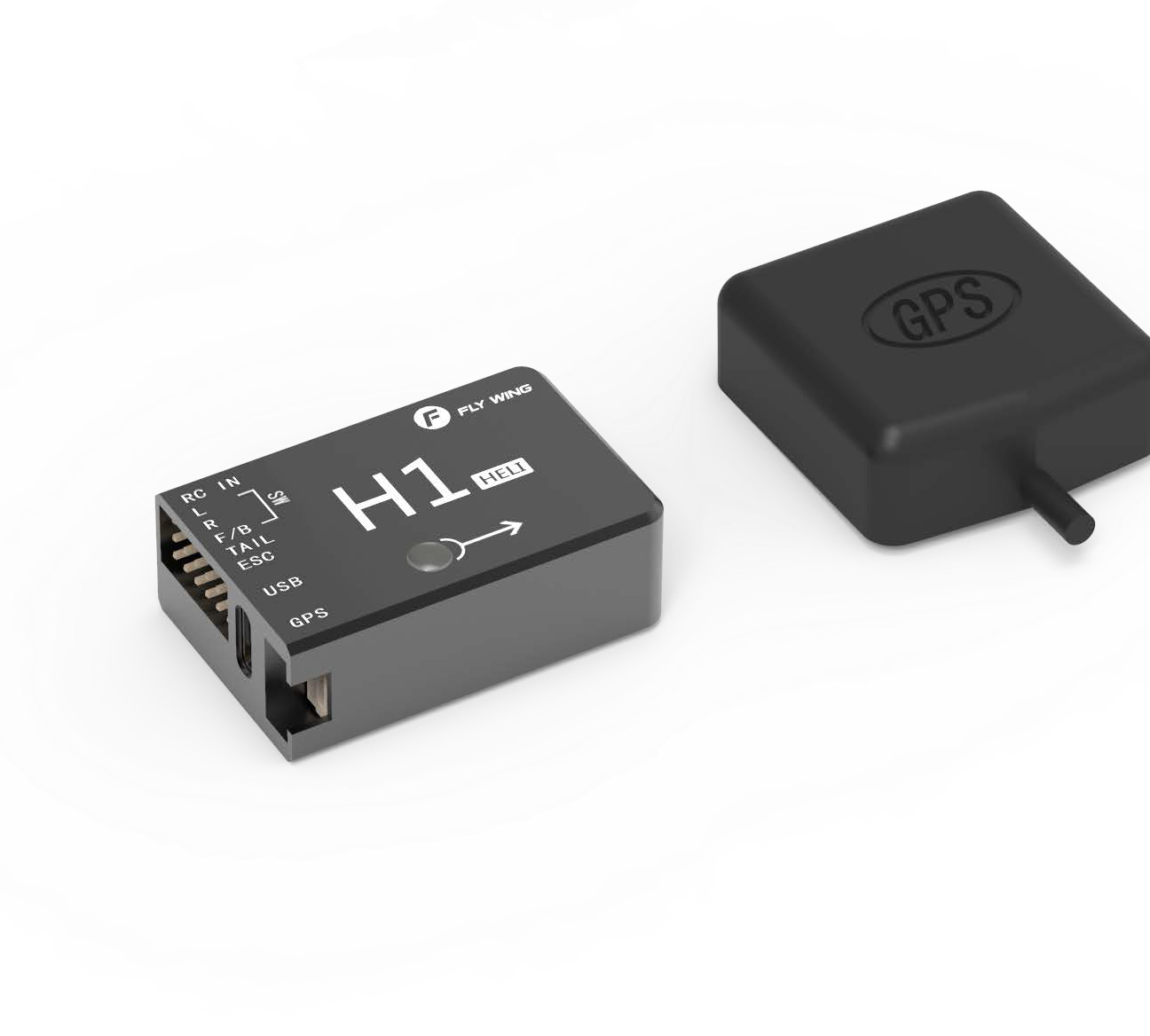
The H1 flight control system consists of a main controller (built-in floating IMU, compass and barometer) and a dual-mode GPS module.
System composition
The main controller is the core module of the flight control system. It uses IMU, barometer, GPS and compass module to achieve precise attitude control and high- precision positioning of the aircraft.
Use the H1 Assistant to configure parameters to the main controller, including installation, flight control, and parameters of other external devices. The LED light shows the current system status in real time, helping you to better understand the current status of the flight control.
Component and port description Flight Control (FC)
The FC has the following features:
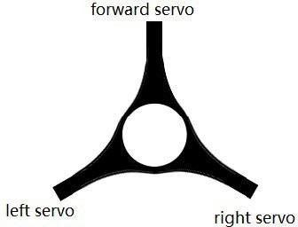
- The FC has 5 PWM outputs, and one receiver input port. The PWM output port is connected to three swash plate servos , main ESC and tail servo(tail motor )
- Built-in IMU and barometer to measure flight attitude and altitude, and with GPS to achieve aircraft horizontal fixed point, thus achieving flight control.
- Support multiple receiver ,receiver input supports PPM, S. Bus and other mainstream single-line mode, automatic identification.
- Use TYPE-C plug, regardless of the positive and negative plug, easy to use.
FC SPCIFICATION AS FOLLOWS:
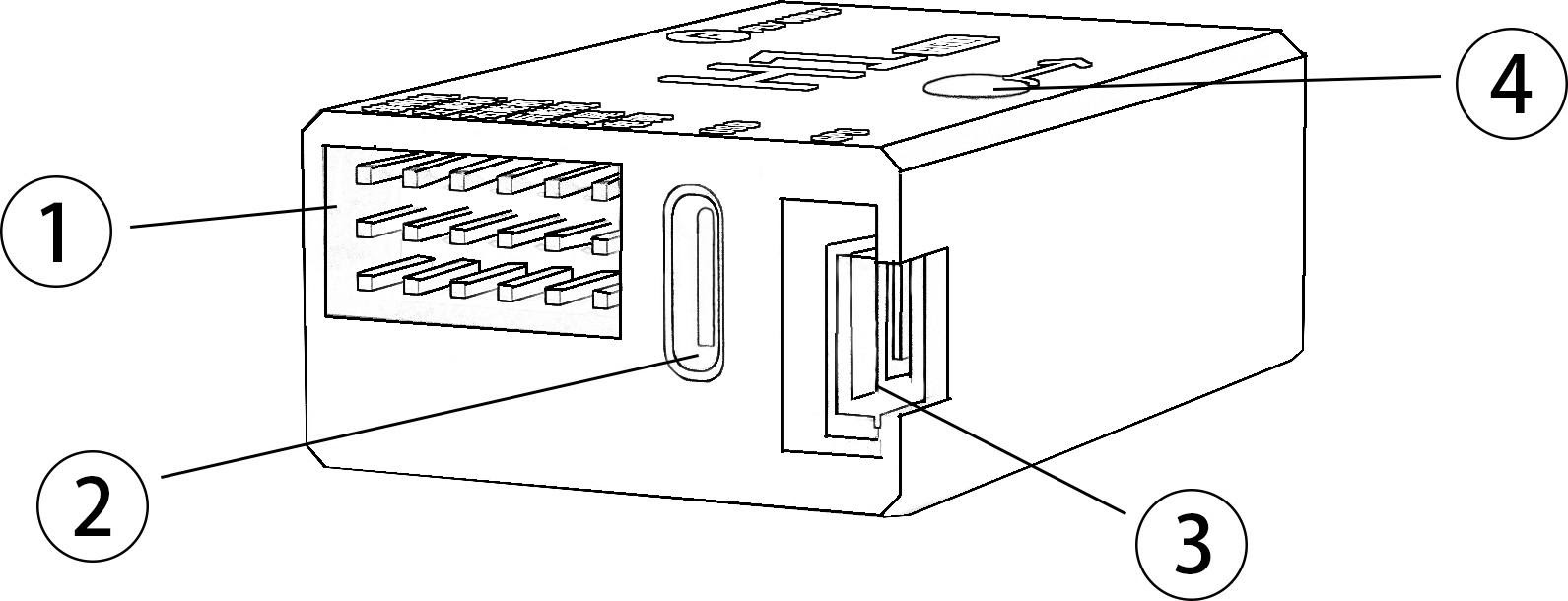
- Pin port Receiver, Servo, ESC plug here
- USB TYPE-C port, connect computer to adjustment
- GPS port GPS and external compass
- interface LED FC status Indicator
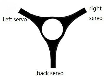
Support swashplate Type:
GPS module:
The GPS module includes a GPS/GLONASS dual-mode receiver and a compass. The compass is used to measure the geomagnetic field and, together with GPS, achieves the horizontal orientation of the aircraft. Calibrate the compass before use and avoid storing and using it in a ferromagnetic environment。
INSTALL
Install procedure
Please read this section carefully and follow the procedure below to install and set up your flight control system to ensure that the system works properly.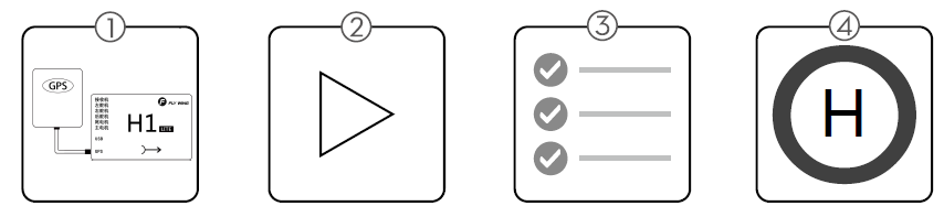
- Ensure that the modules required for installation are complete .
- Watch instructional video (www.flywingrc.com):
- Watch the installation demo and module connection video, install the FC system to the aircraft and connect it properly.
- Watch the software assistant video, run the assistant , and complete the parameter settings according to the software guide and embedded instructions.
- Check that the motor settings, remote channel settings, and protection functions are set correctly.
- Confirm that the individual devices connected to the FC are set correctly.
Take the FW450 as an example, the installation effect is as follows:

Ready to install
When use H1,Please prepare helicopter, transmitter system, ESC, servo and battery, act by yourself. Supported devices as follows:
- Helicopter :H3 and HR3 swashplate; Main power is battery or oil; The rear is a variable pitch or motor driven helicopter.
- Servo: Support 1520us wide-duty servo as swashplate servo, support 1520us wide frequency or 760us narrow frequency as the tail servo, the servo working frequency is automatically recognized.
- ESC: Main motor tail motor ESC support standard PWM ESC.
- Receiver: Support S.bus protocol, PPM protocol, Graupner SUMD HD08 protocol
- Battery:3-6S Lipo battery, support voltage check, with low voltage protection.
Download Assistant Software
Download software H1-HeliPlease visit the web to download: https://www.flywingrc.com/software/
The assistant software needs to use Win7 and above. XP can be used, and some compatibility problems may occur.
Install Assistant software
H1-Heli will guide you through the FC system’s parameter settings, please follow the steps below to install Windows Installation and operation on the system:
Support Win7, Win8 , Win10(32 or 64-bit ) system
- Connect the TYPE-C USB port to your PC using the TYPE-C USB cable.
- Run the H1-Heli driver installation package and follow the prompts to install it.
- Double-click the H1-Heli icon to run the assistant software.
For safety reasons, please remove the propeller or disconnect the motor when adjusting. 
 It is recommended to use Win10 64-bit operating system, which has achieved the best experience.If the software still indicates that the flight controller is not found, or the communication interface failed to initialize, install the driver and restart the computer or replace the data line and try again.
Start the Installation
Important: Strictly follow the provided guidelines. Failure to do so may lead to unexpected flight behavior or serious accidents.
Install FC
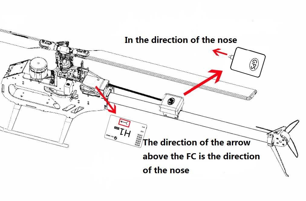
The FC is facing up and parallel to the fuselage, Mounting mark points to the head direction, Center position as close as possible to the center of gravity of the aircraft, Then use double-sided tape to fix it to the body.
Install GPS Module
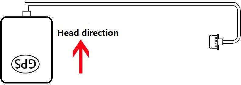
The GPS module is horizontally parallel to the fuselage. GPS installation direction as shown,fix the GPS to the mount with double-sided tape,The fixing seat is fixed on the tail pipe by double-sided tape and cable tie. After installation, try to ensure that the GPS module is level with the aircraft fuselage, the GPS is fixed firmly, and the outlet and the nose are kept level.
GPS use requirements:
- Keep the GPS mark side up and the arrow pointing in the direction of the aircraft nose, otherwise it will not fly normally.
- Please try to keep no tall buildings around and no trees, otherwise it will affect the GPS module.
- The compass is a magnetic sensitive device and should be kept away from strong magnetic fields, electric fields, and electromagnetic fields (such as wires).
- The installation needs to select the appropriate GPS installation location to avoid interference with the compass during operation.
- Face up, do not invert
- If you want to use it under server cold condition, please do the insulation work
- It is recommended to install as close to the vibration as possible, parallel to the fuselage The FC system is not waterproof, oil-proof, or dust-proof.
- Check frequently to ensure that the double-sided tape is securely installed

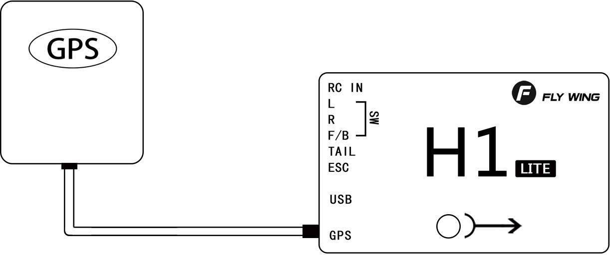
FC System Connection
Follow the instructions below to complete the connection, And use a plastic cable tie to organize the connection to make it clean.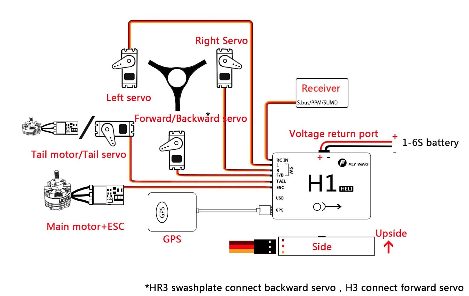
Aircraft equipment connection
When using H1, it is necessary to connect the receiver, ESC, battery and other related aircraft equipment, and set their parameters in H1-Heli, otherwise it may not be able to fly or even cause serious safety accidents.
Receiver
Different types of receiver connection interfaces are different, please connect accordingly. After the connection is successful, the FC will automatically recognize the signal and display the stick information on the software.
Transmitter Setting
- Your transmitter must support “Fail-Safe” Setting the all the channel value of fail-safe by yourself. Otherwise Fail-safe is not available.
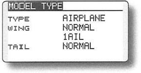
- Your transmitter working mode is “AIRPLANE”
- All channels of the transmitter should work independently, disable Throttle curve and Pitch curve
- You need at least a 5 channel 3 segment switch to be used as a control mode switch, and a 2channel 2 segment switch to stop and start the motor.
- Mechanical setup first ,servo arms are 90 degree to the shaft and all the trims and Sticks are at the center. it should be 0 pitch at mid stick5
For Example as Futaba 14SG
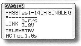
- Setting 7008 receiver as mode B(S.BUS 1), and Connect the flight controller to the S.BUS 1 interface of the receiver
- The transmitter and the receiver are linked, set a new model , set as airplane model. no mixing mode
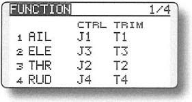
- LINKAGE MENU — FUNCTION 5 channel is set to 3-segment switch (SA), corresponding to the Return mode — GPS mode — 3D manual mode; 7-channel is set to 2-segment switch (SF), corresponding to the shutdown of the motor And start; 8-channel is set to 3-segment switch (SB), corresponding to the shutdown of semi-automatic flight — one-key circle fly-8-flight; 9-channel is set to 2-segment switch (SC), corresponding to one-key reverse Fly forward and backward.

- Enter FAIL SAFE mode and turn on 5-channel F / S. Turn the transmitter’s 5-channel switch (SA) to the Return, and press and hold the “RTN” key for 1 second at the POS position. Then return to the main interface and observe in the software assistant software. When the remote control is turned to the GPS position, turn off the remote control. Will the mode switch prompt the loss of the remote control signal? Will other brands of remote control automatically jump to the home position Bit, 7 channels stay on start.

Parameter settings
Please watch the “Parameter Settings” video, run the Assistant, and follow the software instructions and embedded instructions to complete the parameter settings. The parameter setting process is as follows:
- Ensure that the flight control system is powered properly.
- Connect H1 to your computer.
- Run Assistant. Choose the correct COM port, Click to connect to the computer
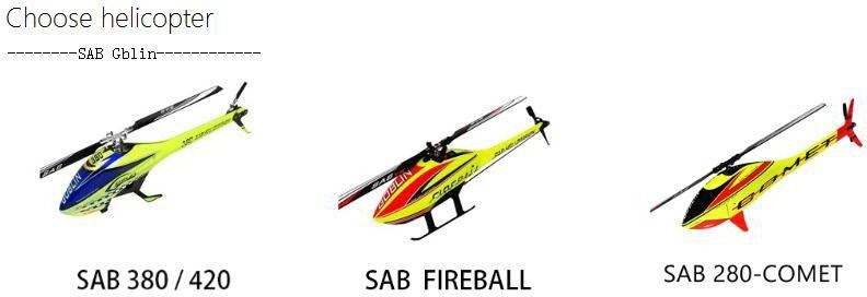
- Click “Install New Helicopter” on the main interface.
- Select the corresponding helicopter
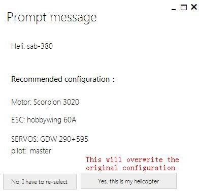
- Confirm helicopter configuration
- Click “Yes, this is my helicopter”, it will write the preset parameter information, and prompt the import is successful without additional adjustments.
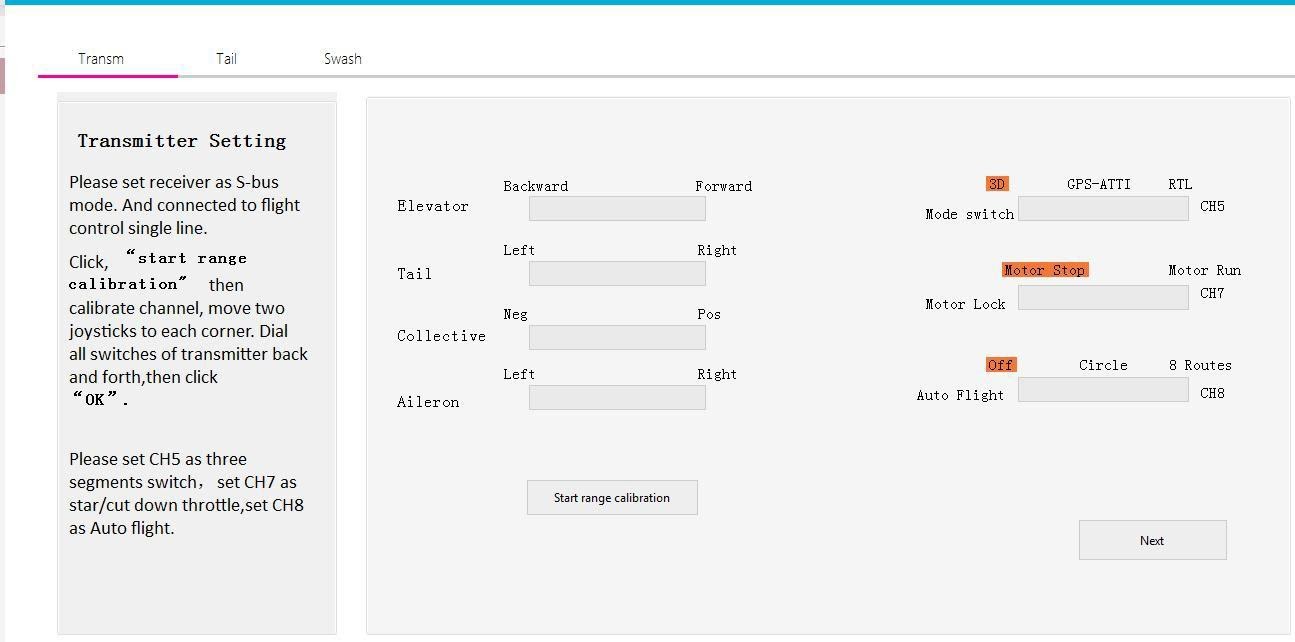
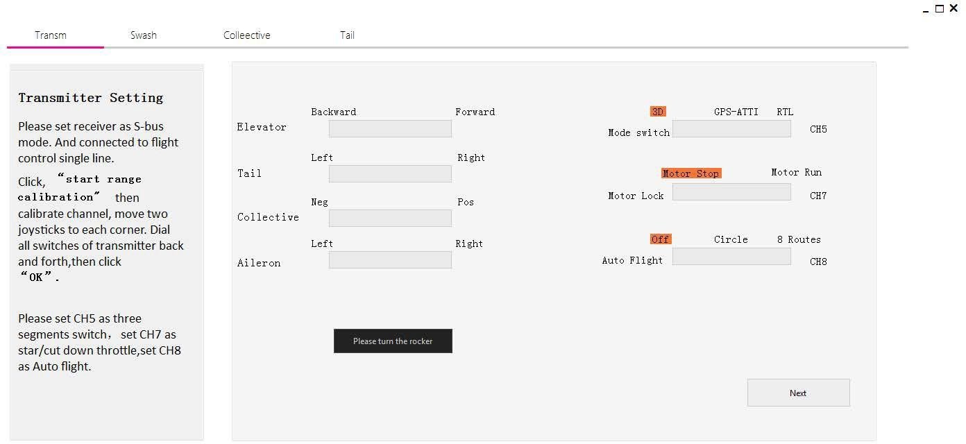
- After the parameters are imported successfully, follow the instructions on the left to perform remote transmitter calibration. If the software display does not match the direction of the remote control (the transmitter pushes forward and the software progress bar is at the “back” end), the corresponding channel will be displayed in the transmitter menu. Reverse (refer to the transmitter manual) until all channels are correct. Set the transmitter 5 channel to three-stage switch for mode switch; set the transmitter 7channel to 2 segment switch for motor safety lock; set the transmitter 8 channel to 2 segment switch for automatic route switch
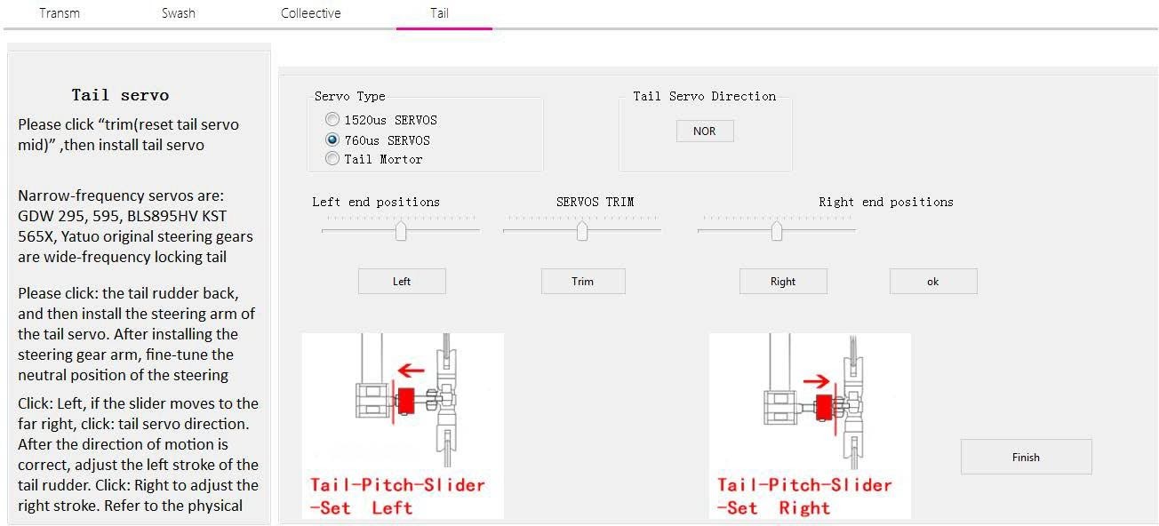
- Enter the tail servo installation option and follow the instructions on the left to determine the neutral position and stroke calibration of the tail servo.
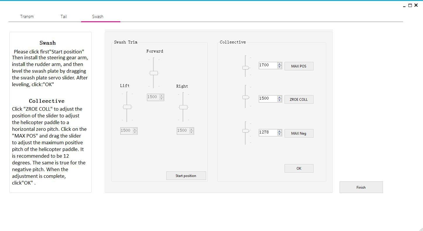
- Enter the swashplate installation option and follow the instructions on the left for swashplate adjustment and pitch adjustment.
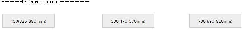
- If it is not the aircraft of this configuration, please select the general model installation at the bottom; select the model of the corresponding size. (The type of aircraft is distinguished by the length of the single rotor.)
- Enter the transmitter calibration option and follow the instructions on the left to perform transmitter calibration. If the software display does not match the direction of the transmitter (the transmitter pushes forward and the software progress bar is at the “back” end), it will correspond in the transmitter menu. The channel is reversed (refer to the transmitter manual) until all channels are correct
- Enter the swash plate installation option, first select the corresponding swashplate type according to the left prompt, then adjust the forward and reverse direction of the steering gear to ensure the correct direction of the steering gear. Finally, fine-tune the steering gear neutral point for swashplate leveling.
- Enter the pitch fine adjustment option, follow the left prompt for zero pitch adjustment, then adjust the positive pitch to 12 degrees and the negative pitch to 12 degrees.
- Enter the tail servo adjustment option, follow the left prompt to select the servo type first, then click the slider to the left, if the slider is to the right, click the tail rudder output to reverse; then click the tail rudder back, calibrate the neutral point, and then click respectively The far left of the slider and the far right of the slider, drag the slider until the slider just touches the maximum limit of the tail axis.


H1 System functions
Compass calibration
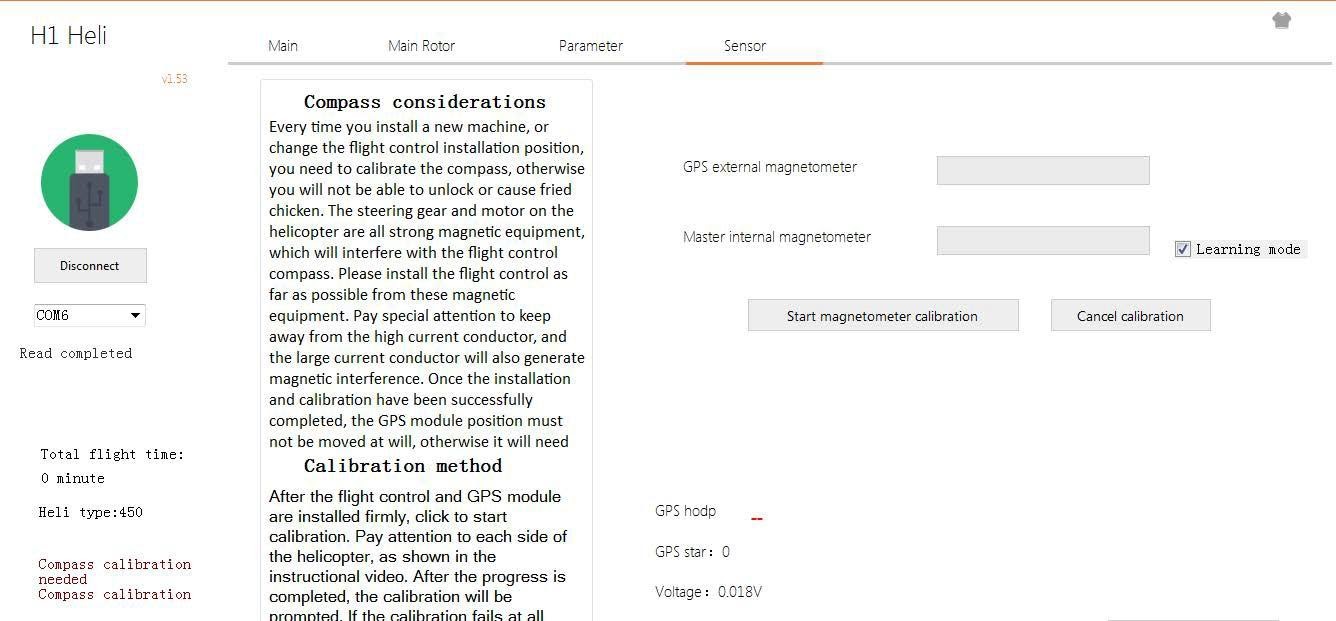
For the first time, compass calibration must be performed, otherwise the system may not work properly, which may affect flight safety. The compass is easily interfered by strong electric fields, strong magnetic fields, and strong electromagnetic fields, which will cause the compass to be abnormal and even cause a flight accident. Frequent calibration allows the compass to work at its best.
Calibration Notes
- Do not calibrate in areas with strong magnetic fields and strong electric fields or large blocks of metal, such as magnets, parking lots, and building areas .
- Do not carry ferromagnetic materials such as keys, watches, etc. with you when calibrating.
- If the compass is calibrated indoors, remember to recalibrate when changing to outdoor flight to prevent the compass from being abnormal during flight due to magnetic field differences between the two areas.
- When there may be steel-like substances affecting the compass, move the aircraft to another location.
Calibration step
Please select an empty space and follow the steps below to calibrate the compass. To see more about compass calibration, watch the related instructional videos.
Method: Calibrate using the assistant software
- Go to the Assistant Software Sensor Calibration option and click Start Calibration.
- Rotate the helicopter horizontally 360° on the front and 360° on the reverse side.
- Rotate the head up and down 360° vertically and turn it 360° vertically downwards.
- Until the calibration progress bar is reached, the calibration is successful.
Need to recalibrate
- The compass data is abnormal and the helicopter status indicator flashes red.
- The flight field is far from the site where the previous compass was calibrated.
- The structure of the helicopter has changed.
- The drift is more serious during flight or it is not possible to fly in a straight line.
Flight Function
Flight mode
Flying has designed a variety of control modes for the user. With different control modes, the flight performance of the helicopter will be different. You can set the remote control 5-channel switch to the flight mode switch through the assistant software.
GPS Positioning mode:
The aircraft utilizes a dual-mode GPS signal that automatically locates at any flight altitude and auto return. 3D Mode:The dual-mode GPS module is not used for positioning with the air pressure leveling system.
It only provides attitude maintenance, no self-stability, 3D flight. Return is not possible.
Return mode:
Same as the GPS positioning mode, using the dual-mode GPS module and air pressure setting to achieve the return function. In this mode, the aircraft will rise to the appropriate altitude, then spin back to the return point, the spin-to-tail will automatically fall down automatically, and the motor will be automatically turned off after the ground.
Automatic route
Automatic route mode
Fly wing designed the auxiliary route practice mode for the user. With this control mode, the aircraft will automatically fly the route (the default 8-word route), at which time the remote control can intervene to achieve the purpose of the exercise. This function requires the 8-channel switch of the remote control software setting remote control to be an automatic route switch.
Automatic route introduction:
The dual-mode GPS module and air pressure setting are used to realize the automatic route function. In this mode, the aircraft will not trigger automatic return. Please pay attention to the battery voltage. You can turn off this function midway, and the aircraft will automatically switch to the previous mode (the GPS mode will automatically switch back to GPS mode before the automatic route)
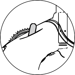
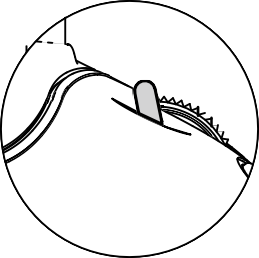
*one key to invert
One key to forward/invert fly
- When using this function, the aircraft will switch between normal flight and invert flight according to a two-segment switch on the transmitter. When the aircraft is flying, switch to invert flight, the aircraft will auto roll over to inverted flight, and the GPS will hover at a fixed point.
- The RETURN function will be invalid in the invert mode. Please pay attention to the battery power .This function requires the 9-channel switch of the transmitter to be set up by one-key through the assistant software. The switch can be used at a height of 10 meters above the ground.
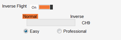
- one key inverted divided into two modes: easy mode and professional mode
Easy mode:
This mode is suitable for beginner operation. It can quickly experience the fun of inverted flight. It needs to be set in the assistant software. When the Invert switch is dialed, the aircraft will auto roll over to the upside down, and the GPS will hover at a fixed point. At this time, the user’s operation mode is the same as that of normal flight. (The throttle stick is pushed up, the airplane climbs upside down, the forward stick is pushed forward, and the aircraft moves towards the nose).
Professional mode:
This mode is suitable for 3D stunt training operations. Basic hover operations of 3D stunts can be performed with GPS fixed-point assistance. It needs to be set in the assistant software. When the Inverted switch is dialed, the aircraft will auto roll to the upside down, and the GPS will hover at a fixed point. At this time, the operation mode of the aircraft is the same as that of the 3D flight (the throttle stick is pushed up, the aircraft descends for upside down, the forward stick is pushed forward, and the aircraft moves toward the tail)
This function is a test function. Due to the performance and power of each aircraft, the rolling effect will be slightly different. This function cannot be turned on within the default altitude of 10 meters. The user opens this function by default and knows that this function is a test function. The adverse effects and consequences of aircraft failure caused by using this function are borne by the user.
In GPS mode, if the satellite signal is not good enough to take off, please move the aircraft to the open space.
In manual mode, if the satellite is not good, it can take off, but the accuracy of the return point cannot be guaranteed. If the GPS signal is still poor after takeoff, the dialing to GPS mode will be invalid and remain in the current mode.
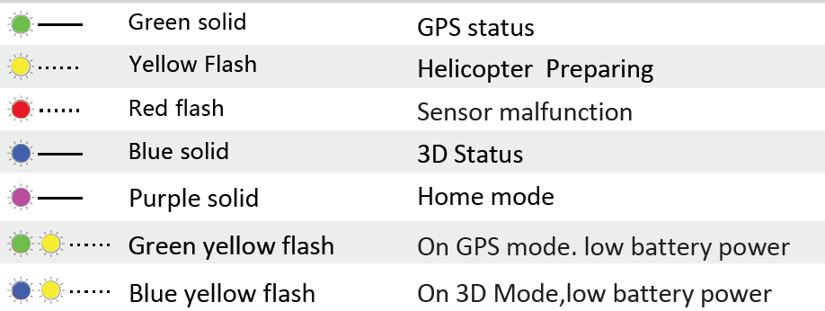
Flight mode indicator
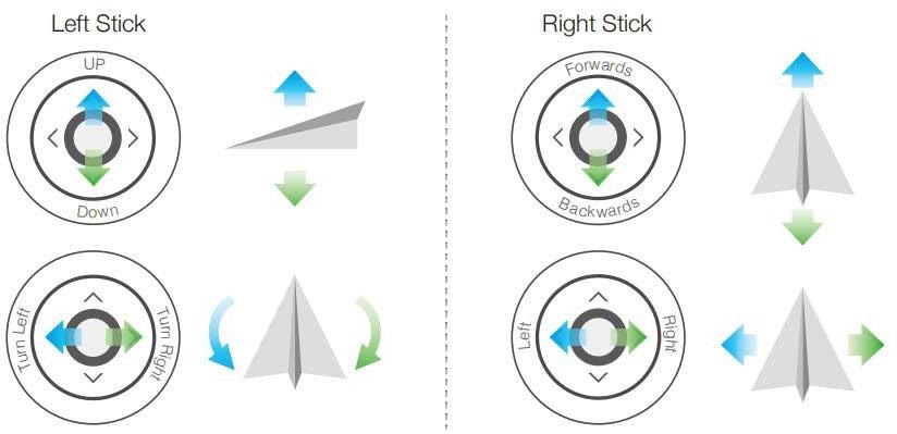
Fly Control (Manual Fly)
Push both sticks to the bottom outer corners to unlock, then dials 7 channels to unlock the motor
![]()


Attitude control
Take Mode 2 (left hand throttle) as an example.
Return protection
There are three ways to return: Out of control return, one-button return , low-voltage return.
Out of control return
When the GPS signal is good, the compass works normally, and after the return point is successfully recorded , if the transmitter signal is interrupted for more than 3 seconds, the FC system will control the aircraft to fly back to the most recently recorded return point at a height of 15 meters. . If the signal returns to normal during the return flight, the return flight process will continue, but the user can control the flight through the transmitter and cancel the return flight. This function needs to jump to the return position when 5 channels of runaway protection are set in the remote control.
When the LED yellow light flashes slowly or the GPS does not work, the return flight cannot be achieved. During the return flight, the aircraft cannot avoid obstacles, so check the surrounding environment before take-off to avoid objects exceeding 15 meters. When the aircraft rises to 15 meters and returns to the return point, the user can fine-tune the landing point through transmitter.
The one-button return mode can be activated by the transmitter mode (5 channels), and the return process is consistent with the uncontrolled return. When using the remote control receiving system, the user needs to assign a switch on the transmitter as the mode switch button (5 channels) and set it in the assistant software.
Low-voltage return
Low voltage return is achieved by judging the voltage.When the voltage is too low, the motor may not be able to output enough power. At this time, the user should land the aircraft as soon as possible, otherwise the aircraft will fall directly, causing damage to the aircraft or causing other dangers. To prevent unnecessary hazards due to insufficient battery voltage, the flight control system will determine if the current voltage is sufficient. (currently supports 3S, 4S, 6S intelligent judgment)
If the current voltage is insufficient, the aircraft will be forced to return. During the descent, the aircraft can be fine-tuned to the landing point by the remote control (if the remote control signal is normal).
Flight restrictions and no-fly zone
According to the air traffic control regulations of ICAO and national air traffic control and the regulations governing drones, drones must fly in the prescribed airspace. For flight safety reasons, users are required to consciously abide by local laws and regulations to use this product more safely and legally.
In a safe flight (GPS) state, the no-fly zone affects flight in conjunction with altitude and distance limits, and the airspace that the aircraft can fly is the intersection of all restricted airspace. The aircraft is only height-limited in a safe flight (no GPS) and the maximum altitude of the actual flight will not exceed 120 m*.
| Paraments | |
|
Helicopter type |
HR3 Flybarless Swashplate
H3 Flybarless Swashplate |
| Battery type | 3S,4S ,6S Lipo battery |
|
Receiver |
S.bus PPM
SUMD HD 08 |
| Assistant operating system requirements | Win7,Win8,Win10(32 or 64 bits) |
| Rated system power | 2W |
| Rated peak power | 4 W |
| Voltage input range | 6.4-8.4V,ESC BEC supply power(cann’t use 5V BEC) |
| Size | FC:31.4mm × 48.5mm × 18.5 mm
GPS:39 mm × 46 mm × 15mm |
| Working temperature | -10° C to 55° C |
|
Weight |
FC:38.7g GPS:28.1 g |
| Hover accuracy (GPS mode) | Vertical :± 0.5 m,horizontal:± 1.5 m |
| Maximum wind resistance | 10 m/s |
| Maximum yaw rate | 3D mode about300° /s |
| Maximum tilt angle | 45°(default 35° ) |
| Maximum rising speed | 4 m/s |
| Maximum falling speed | 4m/s |
Fly Wing H1 V2.2 User Manual – Fly Wing H1 V2.2 User Manual –
[xyz-ips snippet=”download-snippet”]