Multi-Rotor Brushless ESC User Manual
X-Cross BL-32

Thank you for using our product. Any Improper operation may cause personal injury or damage to the product and related equipments. This high power system for RC model can be dangerous ,we strongly recommend reading the user manual carefully and completely. We will not assume any responsibility for any losses caused by unauthorized modifications to our product. We have the right to change the design, appearance, performance and usage requirements of the product unannounced.
01 Main features
- ARM 32-bit Cortex MCU, frequency up to 48 MHZ.
- BLHeli_32 firmware,which is designed for superior functionality and performance.
- Supports regular 1-2ms pulse width input, as well as Oneshot125 (125-250us), Oneshot42 (41.7-83.3us) and Multshot (5- 25us). The input signal is automatically detected by the ESC upon power up.
- Dshot signal is supported at any rate up to at least Dshot1200.
- Damped light does regenerative braking, causing very fast motor retardation, and inherently also does active freewheeling.
- The ultra narrow design can effectively reduce wind resistance in flight, especially for ultra narrow arm drone.
- The silicone twisted-pair of the throttle signal cable effectively reduces the crosstalk caused by signal transmission, and makes flight more stable.
- Aluminum heat sink effectively slow down the temperature rise.
02 Specifications

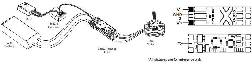
03 Connect diagram
*Please ensure all solder joints are insulated with heat shrink where necessary.
04 Programming parameter
Programming parameters below can be accessed from the configuration software (BLHeliSuite32):
- Rampup power:Rampup power can be set to relative values from 3% to 150%. This is the maximum power that is allowed when ramping up at low rpms and during startup. For low rpms, the maximum power to the motor is limited, in order to facilitate detection of low BEMF voltages. Rampup power also affects bidirectional operation, as the parameter is used to limit the power applied during direction reversal. During startup, the actual applied power depends on throttle input, and can be lower than the maximum level set by the rampup power parameter, but the minimum level is a quarter of the maximum level.
- Motor timing:Motor timing can be set between approximately 1° and approximately 31° in approximately 1° increments (actual accurate values here are 15/16ths of a degree). Typically a medium setting will work fine, but if the motor stutters it can be beneficial to increase timing. Some motors with high inductance can have a very long commutation demagnetization time. This can result in motor stop or stutter upon quick throttle increase, particularly when running at a low rpm. Setting timing to high will allow more time for demagnetization, and often helps.
- PWM frequency:Motor pwm frequency can be programmed between 16kHz and 48kHz. Higher pwm frequency can run motors smoother. Programmable frequency also allows for moving of small but potentially disturbing humps in the throttle response. All ESCs have these bumps, with BLHeli_32 they can be moved in the rpm range, to a place where the system has low sensitivity to them.
- Demag compensation:Demag compensation is a feature to protect from motor stalls caused by long winding demagnetization time after commutation. The typical symptom is motor stop or stutter upon quick throttle increase, particularly when running at a low rpm. As mentioned above, setting high commutation timing normally helps, but at the cost of efficiency. Generally, a higher value of the compensation parameter gives better protection. If demag compensation is set too high, maximum power can be somewhat reduced.
- Maximum Acceleration:Maximum acceleration can be set between 0.1%/ms and 25.5%/ms. It can also be set to maximum, in which case acceleration is not limited. Limiting acceleration is primarily intended as a backup parameter that can be used in cases where too hard acceleration gives desyncs. When setting to e.g. 10%/ms, it means that the power applied to the motor is not allowed to increase by more than 10% per millisecond.
- Motor Direction:Rotation direction can be set to fwd/rev/bidirectional fwd/bidirectional rev. In bidirectional mode, center throttle is zero and above is fwd rotation and below is reverse rotation. When bidirectional operation is selected, throttle calibration is disabled.
- Startup Beep Volume:Sets the strength of beeps under normal operation.
- Beacon/Signal Volume:Sets the strength of beeps when beeping beacon beeps. The ESC will start beeping beacon beeps if the throttle signal has been zero for a giventime. Note that setting a high beacon strength can cause hot motors or ESCs!
- Beacon delay:Beacon delay sets the delay before beacon beeping starts.
- Throttle Cal Enable:If disabled, throttle calibration is disabled.
- Min throttle, max throttle and center throttle:These settings set the throttle range of the ESC. Center throttle is only used for bidirectional operation. The values given for these settings are for a normal 1000us to 2000us input signal, and for the other input signals, the values must be scaled. For Dshot input signal, these settings have no effect.
- Thermal protection:Thermal protection can be enabled or disabled. And the temperature threshold can be programmed The programmable threshold is primarily meant as a support for hardware manufacturers to use, as different hardwares can have different tolerances on the max temperatures of the various components used.
- Low RPM power protect:Power limiting for low RPMs can be enabled or disabled. Disabling it can be necessary in order to achieve full power on some low kV motors running on a low supply voltage. However, disabling it increases the risk of sync loss, with the possibility of toasting motor or ESC.
- Low Voltage Protection:Low voltage protection can be set between 2.5V and 4.0V per lipo cell. Or it can be disabled. When enabled, it will limit power applied to the motor if the battery voltage drops below the programmed threshold. This feature is primarily intended for fixed wing crafts.
- Brake on stop:Brake on stop can be set between 1% and 100%, or disabled. When not disabled, brake will be applied when throttle is zero. For nonzero throttle, this setting has no effect.
- LED Control:LEDs can be controlled on ESCs that support it.
- Non Damped Mode:OFF– Damped light is available; ON– No Damped light.
- Music Note Config:Set up personalized music.
- Sine modulation mode:Sine modulation mode can give a few percent more efficient running, as well as smoother running.
- Auto Telemetry:When auto telemetry is enabled, the ESC will autonomously output telemetry at 32ms intervals, regardless of whether or not there are telemetry requests from the input signal.
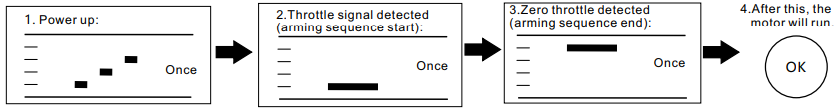
05 Beeps-Normal operation
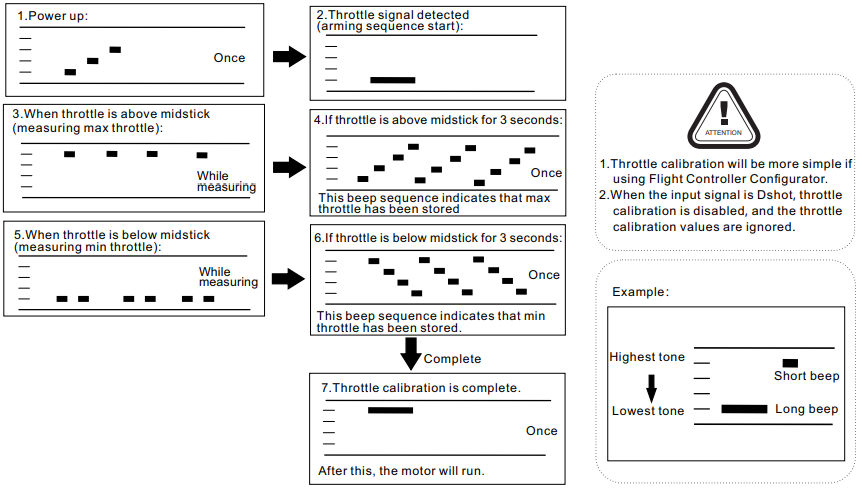
06 Beeps – Throttle calibration
07 Attention
- ESC will automatically detect the input throttle signals every time as soon as it powered on, and then execute the corresponding signal-receiving mode.
- User need to calibrate the throttle range when starting to use a new ESC or another transmitter. When the input signal is Dshot, throttle calibration is disabled.
- When some abnormality occurs in ESC driving the motor or need the motor to reach a higher RPM, user can try to change the timing.
- It is suggested that keep the ground wire in the original signal wire connecting well.
- Please do not exceed the current range. Please use a PDB or Flight Control with currentmeter if OSD is required to display the current.
- Please contact Flycolor sales or technical support for more information.
FlyColor X-CROSS BL-32 Multi-Rotor Brushless ESC User Manual – FlyColor X-CROSS BL-32 Multi-Rotor Brushless ESC User Manual –
[xyz-ips snippet=”download-snippet”]