
Fms 1400mm J-3 V3 Instruction Manual
WARNING
![]()
WARNING: Read the ENTIRE instruction manual to become familiar with the features of the product before operating.
Failure to operate the product correctly can result in damage to the product, personal property and cause serious injury.
This is a sophisticated hobby product and NOT a toy. It must be operated with caution and common sense and failure to do so could result in injury or damage to the product or other property. This product is not intended for use by children without direct adult supervision.
This manual contains instructions for safety operation and maintenance. It is essential to read and follow all the instructions and warnings in the manual prior to assembly, setup or use, in order to operate and avoid damage or serious injury.
Safety precautions and warnings
As the user of this product, you are solely responsible for operating in a manner that does not endanger yourself and others or result in damage to the product or the property of others. This model is controlled by a radio signal subject to interference from many sources outside your control. This interference can cause momentary loss of control so it is advisable to always keep a safe distance in all directions around your model, as this margin will help avoid collisions or injury.
Age Recommendation: Not for children under 14 years. This is not a toy.
- Never operate your model with low transmitter batteries.
- Always operate your model in an open area away from cars, traffic or people.
- Avoid operating your model in the street where injury or damage can occur.
- Never operate the model in populated areas for any reason.
- Carefully follow the directions and warnings for this and any optional support equipment you use (chargers, rechargeable battery packs, etc.)
- Keep all chemicals, small parts and anything electrical out of the reach of children.
- Moisture causes damage to electronics. Avoid water exposure to all equipment not specifically designed and protected for this purpose.
- Never lick or any place of any your model in your mouth as it could cause serious injury or even death.
Safety
Lithium Polymer (Li-Po) Battery Warning
CAUTION: Always follow the manufacturer’s instructions for safe use and disposal of batteries. Fire, property damage, or serious injury can result from the mishandling of Li-Po batteries.
- By handling, charging or using a Li-Po Battery you assume all risks associated with lithium batteries. If at any time the batteries begin to swell or balloon, discontinue use immediately!
- Always store the batteries at room temperature in a dry area to extend the life of the battery. Always transport or temporarily store the battery in a temperature range of 40-120F. Do not store the battery or model in a car or in direct sunlight. If stored in a hot car, the battery can be damaged or even catch fire.
- Never use a Ni-Mh Charger to charge Li-Po Batteries. Failure to charge the battery with a Li-Po compatible charger may cause fire resulting in personal injury and property damage.
- Never discharge Li-Po Cells below 3V.
- Never leave charging batteries unattended.
- Never charge damaged batteries.Charging the Flight Battery Warning
- Use a battery charger that is designed to safely charge the Li-Po Battery. Read the charger instructions care fully before use. When charging the battery, make certain the battery is on a heat resistant surface. It is also highly recommended to place the Li-Po Battery inside a fire resistant charging bag readily available at hobby shops or online.
Introduction
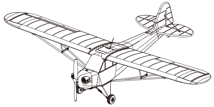
The Piper J-3 Cub is an American light aircraft that was built between 1937 and 1947 By the Piper Aircraft Company as an affordable trainer. The aircraft has a simple, lightweight design which gives it good low-speed handling properties and short-field performance. During the WWII, J-3 Cub was designated as L-4 Grasshopper, used extensively for reconnaissance, transporting supplies, artillery spotting duties and medical evacuation of wounded soldiers.
Like its full-sized counterpart, the all-new FMS 1400mm J-3 V3 has excellent short takeoff and landing (STOL) and slow speed handling characteristics. FMS has dedicated significant amount of resources in making this aircraft as detailed as possible components such as the engine and landing gear, among many others, are replicated in loving detail. Something worth noting is that FMS has made scale floats for the Cub as a response to popular demand from the community.
To mix things up a little, FMS has selected an attractive, historically accurate red paint scheme for the V3 Cub. Not all J-3’s were yellow!
For pilots who are looking for an easy-to-fly, scale aircraft that has gentle trainer characteristics, plenty of power and graceful l ines from the golden-age of flight- the 1400mm FMS J-3 V3 is all of that, and more.
Features:
- Powerful 3536-850KV motor, Predator 40A ESC
- Highly detailed scale engine and landing gear
- Simple structure for quick assembly
- Durable EPO material
- Optional scale floats
Kit contents
Before assembly, please inspect the contents of the kit. The photo below details the contents of the kit with labels. If any parts are missing or defective, please identify the name or part number (refer to the spare parts list near the end of the manual) then contact your local shop or email us:
Specifications
Wingspan: 1400mm(55.1in)Overall length: 900mm(35.4in)Flying weight: ~ 1320gMotor size: 3536-KV850Wing load: 47g/dm²(0.11oz/in²)Wing area: 28dm²(434sq.in)ESC: 40AServo: 9g Servo x 4Recommended battery: 11.1V 2200mAh 25C

A: FuselageB: Main wing setC: Horizontal stabilizerD: Vertical stabilizerE: Main landing gear setF: Supporting barG: Propeller setH: Linkage rods and screwsI: Pipe and Y cableJ:Tail strutK:Float set
Model assembly
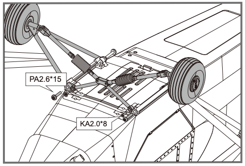
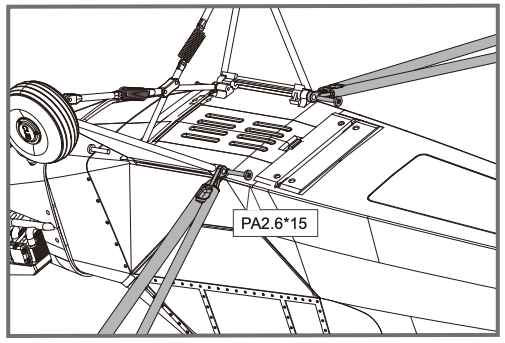
Landing gear set installation
- With the fuselage bottom facing up, carefully Install the landing gear set to the fuselage with the included screws as shown.

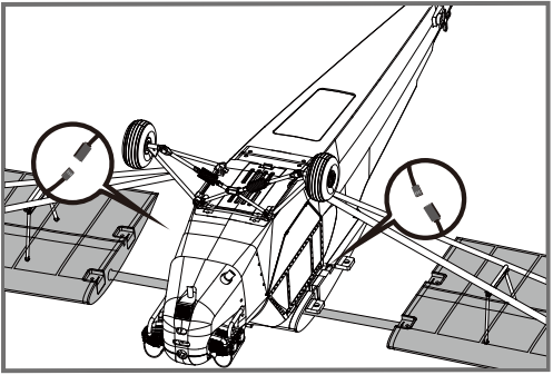
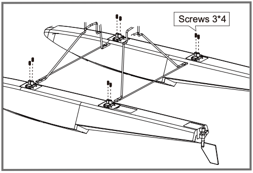
Main wing set installation
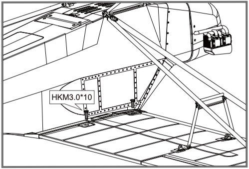
- Have the screws go through the supporting bar and then secure on the base.
- Lock up the fasteners of supporting bar on fuselage as shown.
- Slide the tube into the fuselage then install both wings over the wing tube and into the wing slot of the fuselage.Notice: The connectors on both side should be attached precisely and firmly.
- Secure the wings on the fuselage using the included screws as shown.
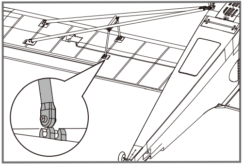
- Lock up the fasteners of supporting bar on main wing as shown.
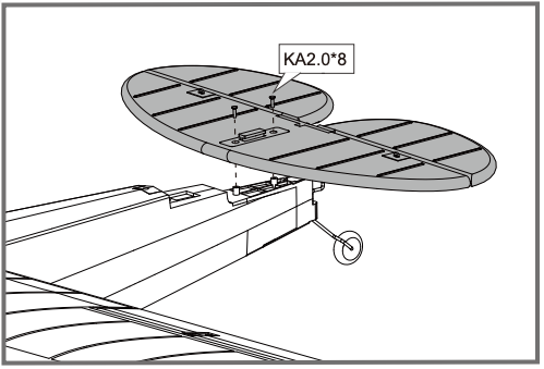
Horizontal stabilizer installation
- Secure the horizontal stabilizer using included screws as shown.
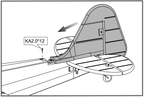
Vertical stabilizer installation
- Slide vertical stabilizer in the rear of the fuselage.
- Secure the vertical stabilizer using included screws as shown.
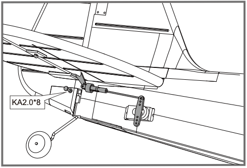
Linkage rod installation
- Make sure the servos are in the neutral position. Install the linkage rod to elevator control horn as shown. Secure the linkage rod in place using the included screw as shown.
- Make sure the servos are in the neutral position. Install the linkage rod to rudder control horn as shown.Note: Please refer to the control horn and servo arm settings in page 11.

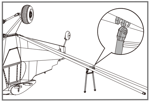
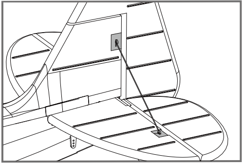
Tail strut installation
- Hook the tail struts to horizontal stabilizer and vertical stabilizer as shown.
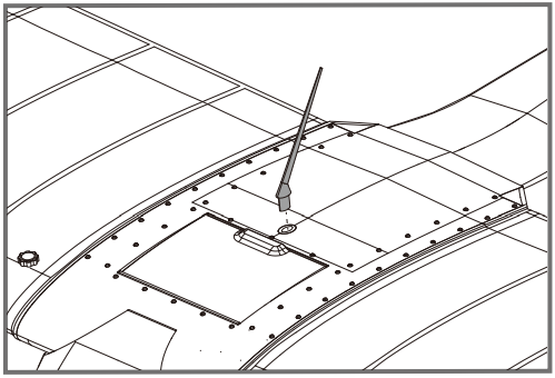
Antenna installation
- Insert the antenna as shown.
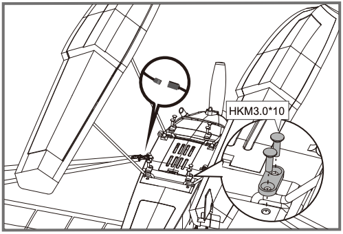
Propeller installation
- Assemble the propeller as shown.

Float set installation
- Assemble the float struts to the plastic holder as shown and secure the struts with screws.
- Secure the float set onto the bottom of fuselage using the included plastic parts and screws as shown.Notice: The connectors on both side should be attached precisely and firmly.
Battery installation
- Pull back on the latch, releasing the canopy.
- Remove the canopy, revealing the battery compartment.
- Apply hook and loop tape to the battery.
- Install a fully charged battery into the battery compartment, with the battery cables facing aft.Note: The center of gravity can be adjusted by moving the battery forward or aft. Having the correct center of gravity is critical to achieving proper flight characteristics.

Receiver diagram
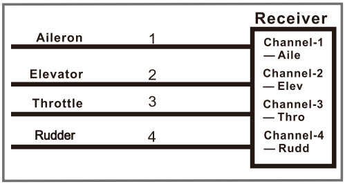 The cables from the servo connector board should be connected to your receiver in the order shown. Note that the LEDs can be powered by any spare channel on the receiver. Tuck the wire leads into the recessed cavity towards the rear of the battery hatch.
Preflight check
Important ESC and model information
- The ESC included with the model has a safe start. If the motor battery is connected to the ESC and the throttle stick is not in the low throttle or off position, the motor will not start until the throttle stick is moved to the low throttle or off position. Once the throttle stick is moved to the low throttle or off position, the motor will emit a series of beeps. Several beeps with the same tune means the ESC has detected the cells of the battery. The count of the beeps equals the cells of the battery. The motor is now armed and will start when the throttle is moved.
- The motor and ESC come pre-connected and the motor rotation should be correct. If for any reason the motor is rotating in the wrong direction, simply reverse two of the three motor wires to change the direction of rotation.
- The motor has an optional brake setting. The ESC comes with brake switched off and we recommend that the model be flown with the brake off. However, the brake could be accidentally switched on if the motor battery is connected to the ESC while the throttle stick is set at full throttle. To switch the brake off, move the throttle stick to full throttle and plug in the motor battery. The motor will beep one time. Move the throttle stick to low throttle or the off position. The motor is ready to run and the brake will be switched off.
- Battery Selection and Installation. We recommend the 11.1V 2200mAh 25C Li-Po battery. If using another battery, the battery must be at least a 11.1V 2200mAh 25C battery. Your battery should be approximately the same capacity, dimension and weight as the 11.1V 2200mAh 25C Li-Po battery to fit the fuselage without changing the center of gravity significantly
Transmitter and model setup
![]() Before getting started, bind your receiver with your transmitter. Please refer to your transmitter manual for proper operation. CAUTION: To prevent personal injury, DO NOT install the propeller assembly onto the motor shaft while testing the control surfaces. DO NOT arm the ESC and do not turn on the transmitter until the Transmitter Manual instructs you to do so.
Before getting started, bind your receiver with your transmitter. Please refer to your transmitter manual for proper operation. CAUTION: To prevent personal injury, DO NOT install the propeller assembly onto the motor shaft while testing the control surfaces. DO NOT arm the ESC and do not turn on the transmitter until the Transmitter Manual instructs you to do so.
Tips: Make sure all control sticks on your radio are in the neutral position (rudder, elevator, ailerons) and the throttle is in the OFF position. Make sure both ailerons move up and down (travel) the same amount. This model tracks well when the left and right ailerons travel the same amount in response to the control stick. Move the controls on the transmitter to make sure the aircraft control surface moves correctly. See diagrams right.
Control throws
The suggested control throw setting for the Piper J-3 Cub V3 are as follows (dual rate setting):
Tips: On the first flight, fly the model in low rate.
The first time you use high rates, be sure to fly at low to medium speeds. High rate, as listed, is only for EXTREME maneuvering.
| High Rate | Low Rate | |
| Elevator | 16mm up/down | 12mm up/down |
| Aileron | 16mm up/down | 12mm up/down |
| Rudder | 18mm left/right | 14mm left/right |
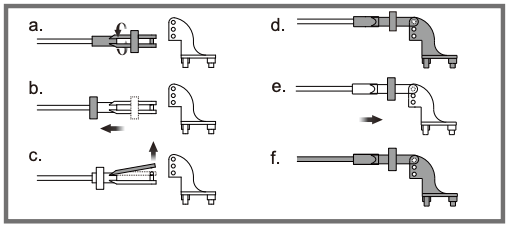
Clevis installation
- Pull the tube from the clevis to the linkage.
- Carefully spread the clevis, then insert the clevis pin into the desired hole in the control horn.
- Move the tube to hold the clevis on the control horn.
 Pull the tube from the clevis to the linkage.
Control horn and servo arm settings
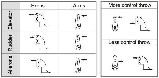 The table shows the factory settings for the control horns and servo arms. Fly the aircraft at the factory settings before making changes.
After flying, you may choose to adjust the linkage positions for the desired control response.
Check the C.G. (Center of gravity)
 When balancing your model, adjust the battery as necessary so the model is level or slightly nose down. This is the correct balance point for your model. After the first flights, the CG position can be adjusted for your personal preference.
- The recommended Center of Gravity (CG) location for your model is(55-65mm) from the leading edge of the main wing (as shown) with the battery pack installed. Mark the location of the CG on top of the wing.
- When balancing your model, support the plane at the marks made on the bottom of the main wing with your fingers or a commercially available balancing stand. This is the correct balance point for your model. Make sure the model is assembled and ready for flight before balancing.
Before flying the model
Find a suitable flying site
Find a flying site clear of buildings, trees, power lines and other obstructions. Until you know how much area will be required and have mastered flying your plane in confined spaces, choose a site which is at least the size of two to three football fields – a flying field specifically for R/C planes is best. Never fly near people – especially children, who can wander unpredictably.
Perform the range check for your plane
As a precaution, an operational ground range test should be performed before the first flight each time you go out. Performing a range test is a good way to detect problems that could cause loss of control such as low batteries, defective or damaged radio components, or radio interference. This usually requires an assistant and should be done at the actual flying site you will be using.
First turn on the transmitter, then install a fully-charged battery into the fuselage. Connect the battery and install the hatch.
Remember, use care not to bump the throttle stick. Otherwise, the propeller/fan will turn and possibly cause damage or injury.
Note: Please refer to your Transmitter Manual that came with your radio control system to perform a ground range check. If the controls are not working correctly or if anything seems wrong, do not fly the model until you correct the problem. Make certain all the servo wires are securely connected to the receiver and the transmitter batteries have a good connection.
Monitor your flight time
Monitor and limit your flight time using a timer (such as on a wristwatch or in your transmitter if available). When the batteries are getting low you will usually notice a performance drop before the ESC cuts off motor power, so when the plane starts flying slower you should land. Often (but not always) power can be briefly restored after the motor cuts off by holding the throttle stick all the way down for a few seconds. To avoid an unexpected dead-stick landing on your first flight, set your timer to a conservative 4 minutes. When your alarm sounds you should land right away.
Flying course
Take off
While applying power, slowly steer to keep the model straight. The model should accelerate quickly. As the model gains flight speed you will want to climb at a steady and even rate. It will climb out at a nice angle of attack (AOA).
Flying
Always choose a wide-open space for flying your plane. It is ideal for you to fly at a sanctioned flying field. If you are not flying at an approved site always avoid flying near houses, trees, wires and buildings. You should also be careful to avoid flying in areas where there are many people, such as busy parks, schoolyards, or soccer fields. Consult laws and ordinances before choosing a location to fly your aircraft. After takeoff, gain some altitude. Climb to a safe height before trying technical manoeuvres, including high speed passes, inverted flight, loops, and point rolls.
Landing
Land the model when you hear the motor pulsing (LVC) or if you notice a reduction in power. If using a transmitter with a timer, set the timer so you have enough flight time to make several landing approaches.
The model’s three point landing gear allows the model to land on hard surfaces. Align model directly into the wind and fly down to the ground. Fly the airplane down to the ground using 1/4-1/3 throttle to keep enough energy for proper flare. Before the model touches down, always fully decrease the throttle to avoid damaging the propeller or other components. The key to a great landing is to manage the power and elevator all the way to the ground and set down lightly on the main landing gear. After a few flights you will find the model can be set down lightlyon the mains and you can hold the nose wheel off balancing the model on the mains until it slows and gently settles the nose.
Maintenance
Repairs to the foam should be made with foam safe adhesives such as hot glue, foam safe CA, and 5min epoxy. When parts are not repairable, see the Spare Parts List for ordering by item number.
Always check to make sure all screws on the aircraft are tightened. Pay special attention to make sure the spinner is firmly in place before every flight.
Trouble shooting

Spare parts list content
| FMSRK101 | Fuselage |
| FMSRK102 | Main wing set |
| FMSRK103 | Horizontal stabilizer |
| FMSRK104 | Vertical stabilizer |
| FMSRK105 | Cowl |
| FMSRK106 | Linkage rod |
| FMSRK107 | Supporting bar set |
| FMSRK108 | Front landing gear set |
| FMSRK109 | Sticker |
| FMSRK110 | Propeller plate |
| FMSRK111 | Pipe |
| FMSRK112 | Screw set |
| FMSPROP021 | Propeller |
| FMSDZ007 | Motor shaft |
| FMSDJ007 | Motor mount |
| FMSBM009 | Motor board |
| PRKV850 | Brushless motor |
| PRESC001 | 40A ESC |
| FMSSER9GPW | 9g Servo(with waterproof function) |
| FMSCHR01 | Charger |
| FMSFLT004 | Float Set |
Visit our website: www.fmsmodel.com to see photo of this product. Enter the key word “ESC” in the search bar for the stock ESC instruction manual.
Fms 1400mm J-3 V3 Instruction Manual – Fms 1400mm J-3 V3 Instruction Manual –
[xyz-ips snippet=”download-snippet”]