Focusrite HD32R,32-channel Bridge
About this User Guide
This User Guide applies to both the RedNet 5 and RedNet HD32R HD Bridge interfaces. It provides information about installing each unit and how either can be connected into your system.
All references relating to the RedNet 5 are also applicable to the RedNet HD32R. In any instances where names or values differ, the screening or value for the HD32R unit will be appended in square brackets, eg., “Power [PSU A]”.
| HD32RAny information that is relevant to only one device will be separated within a border like this. |
A RedNet System User Guide is also available from the RedNet product pages of the Focusrite website. The Guide provides a detailed explanation of the RedNet system concept, that will help you achieve a thorough understanding of its capabilities. We recommend that all users, including those already experienced in digital audio networking, take the time to read through the System User Guide so that they are fully aware of all the possibilities that RedNet and its software have to offer.
If either User Guide doesn’t provide the information you need for a comprehensive collection of common technical support queries please consult: focusritepro.zendesk.com.
Box Contents
- RedNet 5 [HD32R] unit
- 1 [2] x IEC AC mains cables
- 2 x IEC mains cable retaining clips (Check down below)
- 2m Cat 6 Ethernet cable HD32R only
- Safety information cut sheet RedNet 5 only
- RedNet Getting Started Guide
- Product registration card, provides links to:RedNet ControlRedNet PCIe drivers (included with RedNet Control download)Audinate Dante Controller (installed with RedNet Control)Dante Virtual Soundcard (DVS) Token and download instructions
INTRODUCTION
Thank you for purchasing the Focusrite RedNet 5/HD32R.
RedNet 5/HD32R is a multichannel, bi-directional Dante interface, which allows an Avid® ProTools|HD system direct access to a Dante digital audio networking system.Each unit acts as a 64-channel (32 in/32 out (16×16 at 192kHz)) digital break in/out box and both support a wide range of Pro Tools|HDX and HD cards. Up to six RedNet 5/HD32R modules can be used with a Pro Tools|HDX system and five with Pro Tools|HD, allowing the maximum channel count
| HD32RDual Ethernet connectors (primary and secondary) on the rear-panel allow maximum network reliability with seamless switchover to a standby network in the unlikely event of a network failure. These ports may also be used to daisy-chain additional units when operating in Switched mode.Redundant power supplies (PSU A and B) with separate input sockets on the rear panel allow one supply to be connected to an uninterruptible source. Each PSU’s status can be monitored remotely over the network or from the front panel. |
for either.
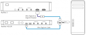
| RedNet 5A Mini DigiLink-to-DigiLink adaptor cable is included to allow compatibility with Pro Tools|HDX or Pro Tools|HD Native systems that use the Mini DigiLink connection. |
Connection to Pro Tools system is via standard DigiLink [Mini DigiLink] ports.
An additional Avid/Digidesign interface may be connected to the expansion port.
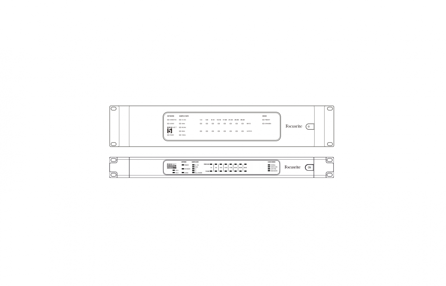
The front panel contains a set of LEDs to confirm network status, sample rate, clock sources and signal presence on both input and output.
INSTALLATION GUIDE
RedNet 5 Connections and Features
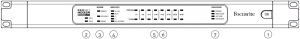
Front Panel
- AC Power Switch
- PowerIlluminates when an AC input is applied and all DC outputs are present.
- RedNet Network Status Indicators:• CONNECTED – Illuminates when the device is connected to an active Ethernet network.• LOCKED – Illuminates when a valid sync signal is received from the network, or when the RedNet 5 unit is Network Leader. Flashes if external clock is selected but not connected.
- RedNet Sample Rate IndicatorsFive orange indicators: 44 .1kHz, 48kHz, 88 .2kHz, 96kHz and 192kHz. Only one of these will be lit at any time to indicate the sample rate at which the system is operating. At 192kHz the channel count will drop to 16 x 16.
- InputsAudio inputs to the network (i.e.. outputs from Pro Tools|HD). Eight tri-colour LEDs indicating the signal level in four consecutively-numbered channels; the colour indicates the highest signal in each group of four:Green: Signal present (illuminates at -42 dBFS)Orange: -6 dBFSRed: 0 dBFS
- OutputsAudio outputs from the network (i.e.. inputs to Pro Tools|HD). Eight LEDs indicating the signal level in the output channels; these function in the same manner as the input LEDs.
- Pro Tools Interface Mode:• PRIMARY – the normal operating mode, in which RedNet 5 appears to Pro Tools as two external 16-channel interfaces.• EXPANSION – this mode should be selected from RedNet Control when the rear panel ‘Expansion’ port is in use. RedNet 5 will now appear to Pro Tools as a single 16-channel interface. This mode should also be used when RedNet 5 is connected to the expansion port of a 16-channel Pro Tools|HD device.
RedNet HD32R Connections and Features
Front Panel
- AC Power Switch
- Power Indicators:• PSU A – Illuminates when an AC input is applied and all DC outputs are present.• PSU B – Illuminates when an AC input is applied and all DC outputs are present.When both supplies are functioning and have AC inputs PSU A will be the default supply.
- RedNet Network Status Indicators:• PRIMARY – Illuminates when the device is connected to an active Ethernet network. Also illuminates to indicate network activity when operating in switched mode.• SECONDARY – Illuminates when the device is connected to an active Ethernet network. Not used when operating in Switched mode.• LOCKED – Illuminates when a valid sync signal is received from the network, or when the RedNet HD32R unit is Network Leader. Flashes if external clock is selected but not connected.
- RedNet Sample Rate IndicatorsFive orange indicators: 44 .1 kHz, 48 kHz, x2 (multiple of 44.1 or 48), x4 (multiple of 44.1 or 48) and sample rate PULL UP/DOWN. These Indicators illuminate individually or in combination to indicate the sample rate being used. For example: for a 96kHz Pull Up/Down setting, the 48kHz, x2 and Pull Up/Down indicators will illuminate. At 192kHz the channel count will drop to 16 x 16.
- From DAWAudio inputs to the network (ie., the outputs from Pro Tools). Eight green LEDs indicating signal present in any of four consecutively-numbered channels; illuminate at -126 dBFS.
- To DAWAudio outputs from the network (ie., the inputs to Pro Tools). Eight green LEDs indicating signal present in the output channels; illuminate at -126 dBFS.
- Clock Source:• INTERNAL – Orange LED, indicates that unit is locked to its internal clock.• WORD CLOCK – Orange LED, illuminates to indicate an external Word Clock sync is in use.• LOOP SYNC – Orange LED illuminates when this device is clocking to Loop Sync.• DAW Leader – Orange LED illuminates when this device is the leader in Pro Tools.
Rear Panels
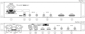
- IEC Mains Inlet [A]Standard IEC receptacle for connection of AC mains. RedNet 5/HD32R features ‘Universal’ PSUs, enabling it to operate on any supply voltage of between 100 V and 240 V AC.Note that initial use requires fitment of the plug retaining clips – Check down below.
1a . IEC Mains Inlet B Input connector for backup mains power source.HD32R Power supply B remains on standby but will seamlessly take over if PSU A develops a fault or loses its mains input supply.If an uninterruptible supply (UPS) is available, it is recommended that this is applied to input B. - Primary Network PortRJ45 [etherCON] connector for the Dante network. Use standard Cat 5e or Cat 6 network cable to connect to a local Ethernet switch to connect the RedNet 5/HD32R to the RedNet network. Adjacent to each network socket are LEDs which illuminate to indicate a valid network connection plus network activity. Check connector pinouts down below.
2a . Secondary Network PortHD32R Secondary Dante network connection where two independent Ethernet links are being used (Redundant mode) or an additional port on an integral network switch on the primary network (Switched mode). - Word Clock OutProvides an output of the chosen system clock reference (can be switched between base rate or network rate).
- Word Clock InAllows synchronization of the Dante network to house word clock.
- Loop Sync In / OutBNC sockets allow RedNet 5/HD32R to form part of the sync interconnection when standard Pro Tools I/O units also form part of the system.Check down for further LOOP SYNC connection details.
- Pro Tools PrimaryDigiLink [Mini-DigiLink] connector; use a standard Pro Tools I/O cable to link this to a port on the Pro Tools|HD/HDX PCIe card.Use the supplied DigiLink-to-Mini DigiLink adaptor cable if necessary.
- Pro Tools ExpansionConnects to a 2nd Pro Tools|HD I/O interface when unit is operating in Expansion Mode. In this mode RedNet 5/HD32R provides 16 channels of I/O (16 in, 16 out) instead of 32.Check for connector pinouts.
Power Connection
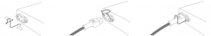
IEC Power Cord Retaining Clips
This information is only applicable to the RedNet HD32R.
RedNet HD32R is supplied with two IEC power cord retaining clips. These prevent accidental disconnection of a power cord during use. When the unit is first installed, the retaining clips will need to be attached to the power input sockets on the rear panel.
Insert each clip by squeezing together the legs as shown in the first image below, aligning the pins with the through-holes on the IEC fixing posts one at a time, and then releasing.
Ensure that the orientation of each clip is as shown in the other images below or its effectiveness will be compromised.
Physical Characteristics – RedNet 5
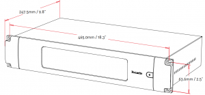
RedNet 5 dimensions are illustrated in the diagram above.
RedNet 5 requires 2U of vertical rack space and at least 300 mm of rack depth, to allow for cables.RedNet 5 weighs 4.61 kg and for installations in a fixed environment (eg., a studio), the front-panel mounting screws will provide adequate support. If the units are to be used in mobile situation (eg., flight-cased for touring, etc.), consideration should be given to using side support rails within the rack.
RedNet 5 generates little significant heat and is cooled by natural convection. The ambient operating temperature of the device is 50 degrees Celsius.
Ventilation is via slots in the enclosure at both sides. Do not mount RedNet 5 immediately above any other equipment which generates significant heat, for example, a power amplifier. Also, ensure that when mounted in a rack, the side vents are not obstructed.
Power Requirements
RedNet 5 is mains-powered. It incorporates a ‘Universal’ power supply, which can operate on any AC mains voltage from 100 V to 240 V. The AC connection is made via a standard 3-pin IEC connector on the rear panel.
A mating IEC cable is supplied with the unit – this should be terminated with a mains plug of the correct type for your country.
The AC power consumption of the RedNet 5 is 30VA.
Please note that there are no fuses in RedNet 5, or other user-replaceable components of any type.Please refer all servicing issues to the Customer Support Team (see “Customer Support and Unit Servicing” Down below).
Physical Characteristics – RedNet HD32R
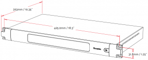
RedNet HD32R dimensions are illustrated in the diagram above.
RedNet HD32R requires 1U of vertical rack space and at least 350 mm of rack depth, to allow for cables. RedNet HD32R weighs 3.9 kg and for installations in a fixed environment (eg., a studio), the front-panel mounting screws will provide adequate support. If the units are to be used in a mobile situation (eg., flight-cased for touring, etc.), consideration should be given to using side support rails within the rack.
RedNet HD32R generates little significant heat and is cooled by natural convection. The ambient operating temperature of the device is 50 degrees Celcius.
Ventilation is via slots in the enclosure at both sides. Do not mount RedNet HD32R immediately above any other equipment which generates significant heat, for example, a power amplifier. Also, ensure that when mounted in a rack, the side vents are not obstructed.
Power Requirements
RedNet HD32R is mains-powered. It incorporates two ‘Universal’ power supplies, which can operate on any AC mains voltage from 100 V to 240 V. The AC connection is made via a standard 3-pin IEC connector on the rear panel.
When PSU A & PSU B are both connected, PSU A becomes the default supply and therefore draws more current than B. If a backup mains supply is provided from an uninterruptible source, it is recommended that this is connected to input B.
Two mating IEC cables are supplied with the unit – these should be terminated with mains plugs of the correct type for your country.
The AC power consumption of the RedNet HD32R is 30VA.
Please note that there are no fuses in RedNet HD32R, or other user replaceable components of any type. Please refer all servicing issues to the Customer Support Team (see “Customer Support and Unit Servicing” Check down below)
REDNET 5/HD32R OPERATION
First Use and Firmware Updates
Your RedNet 5/HD32R may require a firmware update* when it is first installed and switched on.Firmware updates are initiated and handled automatically by the RedNet Control application.
*It is important that the firmware update procedure is not interrupted – either by switching off power to the RedNet 5/HD32R or the computer on which RedNet Control is running, or by disconnecting either from the network.
From time to time Focusrite will release RedNet firmware updates within new versions of RedNet Control. We recommend keeping all RedNet units up to date with the latest firmware version supplied with each new version of RedNet Control.
Pull Up and Pull Down Operation
This information is only applicable to the RedNet HD32R.
RedNet HD32R is able to operate at a specified pull up or pull down percentage as selected in the Dante Controller application
INTERFACING TO PRO TOOLS
RedNet 5/HD32R units are connected to a Pro Tools|HD/HDX system using standard DigiLink/Mini DigiLink cables (not supplied).
RedNet 5 and HD32R units provide 32 inputs and 32 outputs, compared to the 16 inputs and 16 outputs provided by Pro Tools|HD I/O audio interfaces. This means that each RedNet 5/HD32R appears to the Pro Tools system as two 16 channel I/O units.
Pro Tools|HDX
Each Pro Tools|HDX PCIe card provides two Mini DigiLink ports (giving the card a capacity of 64 inputs and 64 outputs), thus two RedNet 5/HD32R units may be connected to each card. A maximum of six RedNet units can be connected, giving a total input and output capability of 192 inputs and 192 outputs. Connect the RedNet’s rear panel PRIMARY port to a Mini DigiLink connector on the ProTools|HDX system. RedNet 5s will need to use the DigiLink-to-Mini DigiLink adaptor supplied with each to complete the interconnection.
Pro Tools|HD
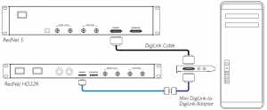
Each Pro Tools|HD card has one DigiLink port (giving the card a capacity of 32 inputs and 32 outputs), thus one RedNet 5/HD32R may be connected to each card. A maximum of three RedNet 5s may be connected, giving a total input and output capability of 96 inputs and 96 outputs. Connect the RedNet’s rear panel PRIMARY port to a DigiLink connector on the Pro Tools|HD system. RedNet HD32Rs will need to use a DigiLink-to-Mini DigiLink adaptor (not supplied) to complete the interconnection.
Multiple I/O Units
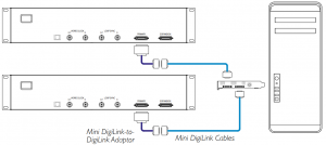
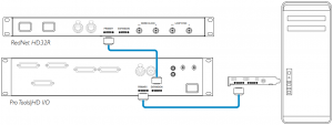
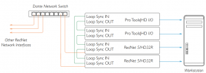
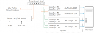
The diagrams below show two different methods of connecting two RedNet HD32R units to a Pro Tools|HDX system using Mini DigiLink cables.
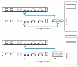
RedNet 5 units can be connected in the same way but will additionally require the Mini DigiLink-to DigiLink adaptors.
Pro Tools Setup
On the Pro Tools Hardware Setup page (click Setup > Hardware), select each RedNet 5/HD32R unit in turn and click the Set to Default button. This will ensure that the RedNet unit is correctly configured for use with Pro Tools.
Sample RateRedNet 5/HD32R units will use the same sample rate at which the Pro Tools session is running. It is important that any devices routed to or from RedNet 5/HD32R unit are also set to the same sample rate. In simple systems, where the entire network is running at the same sample rate, RedNet Control can be used to globally change the sample rate of all units. If a more complex system is in use, where different units are running at different sample rates, please ensure that the units’ sample rates are correctly set using Dante Controller.
Using RedNet 5 with other Pro Tools|HD interfaces
RedNet 5/HD32R interfaces may be freely intermixed with other Pro Tools|HD I/O audio interfaces.However, it is important to remember that each Pro Tools|HD I/O audio interface allows for 16 channels bidirectionally, whereas a RedNet 5/HD32R allows for 32 channels.
In most situations, RedNet 5/HD32R will be connected directly to a DigiLink [Mini DigiLink] port on the Pro Tools|HD or HDX card and will be used in Primary Mode (full 32 channel operation). However, if a free port is not available, then RedNet 5/HD32R can be used in Expansion Mode. This mode reduces the available channels in RedNet 5/HD32R to 16 and permits the connection of an existing 16 channel Pro Tools|HD interface to its EXPANSION port; therefore providing a combined total of 32 channels at the HD or HDX card’s port. This is achieved by selecting Expansion Mode in RedNet Control (see page 21 for more details).When connecting devices in Expansion Mode, the Pro Tools|HD card should be connected to the
PRIMARY port of the first interface. Its EXPANSION port should then connect to the PRIMARY port of the second interface. See below:
Setting the Clock Source
IMPORTANT – The diagrams in the preceding section only illustrate the DigiLink interconnections between system elements. However, consideration must also be given to word clock source and routing. It is very important to arrange word clock routing correctly when using multiple I/O units.
The rules for setting clock source depend on the complexity of the system being implemented.They are explained by the following four examples, which collectively cover almost every likely interconnection situation.
Note: For clarity, only non-redundant networks are shown
Situation 1 – Single Pro Tools System with RedNet 5/HD32Rs only
In this configuration, one or more RedNet 5/HD32R units are the only audio interfaces on the Pro Tools system.
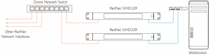
- Select one of the RedNet 5/HD32R units to be the Network Leader in RedNet Control.Any of the RedNet units on the network may be selected as the network leader, but it is recommended that one of the RedNet 5/HD32R units is chosen.
- In Pro Tools, select the unit chosen in Step 1 to also be the Pro Tools Clock Source.Again, any of the RedNet units on the network can be selected as the clock source, but it is recommended that the unit chosen as the Network Leader is selected.
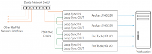
Situation 2 – Single Pro Tools System with both RedNet and Pro Tools interfaces
Pro Tools|HD I/O audio interfaces may be used as audio I/O on the same Pro Tools system as RedNet 5/HD32Rs. Choose either audio interface you wish to be the clock source – this may be either a RedNet 5/HD32R or a Pro Tools audio interface.
- If a RedNet I/O is to be the clock source:

- Select one of the RedNet 5/HD32R units to be the Clock Source in RedNet Control.It is recommended that this is the same unit as the RedNet network leader.
- Using 75Ω BNC-BNC cables, create a Loop Sync ‘daisy chain’ between every I/O unit so that each LOOP SYNC OUT connector is linked to LOOP SYNC IN on the next unit in the chain.
- Complete the chain by connecting LOOP SYNC OUT on the last unit back to LOOP SYNC IN on the first unit.
- If a Pro Tools|HD I/O audio interface is to be the clock source:
- Create the Loop Sync ‘daisy chain’ between all I/O units (as described in steps 2 and 3 in the example above).
- In RedNet Control, set the RedNet unit selected above to be the network leader.
- Also in RedNet Control, set the Clock Source for this same unit to Loop Sync.
Situation 3 – Pro Tools System where another RedNet unit is the clock leader
In this system, another RedNet interface on the RedNet network is the clock leader (ie., not one of the RedNet 5 or HD32Rs). For example, this situation might arise if there is also a RedNet 3 or RedNet D16 resolving its clock from an audio input or word clock input.
- In RedNet Control, Tools menu, set the appropriate RedNet unit as the clock leader.
- Set one RedNet 5/HD32R unit to be the Pro Tools clock source. (Pro Tools Setup > Hardware > Clock Source to Internal for one RedNet 5/HD32R.)
- If there are additional Pro Tools interfaces in the system, connect LOOP SYNC OUT on one RedNet 5/HD32R unit to LOOP SYNC IN of a Pro Tools interface, and ‘daisy-chain’ all units together in the usual closed-loop manner.
Situation 4 – Multiple Pro Tools Systems, each with RedNet 5/HD32R I/O
The guiding rules here are:
- One of the Pro Tools systems should be configured as described for any of Situations 1, 2 or 3 above.
- All other Pro Tools systems must be set up as described in Situation 2, with one of the RedNet units on each being assigned as the clock leader.
- When more than one Pro Tools system is connected to the RedNet network, all audio routing must be established using Dante Controller rather than RedNet Control.
- For audio to be transferred between Pro Tools systems, all systems must be set to run at the same sample rate.
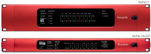
OTHER REDNET SYSTEM COMPONENTS
The RedNet hardware range includes various types of I/O interface and PCIe/ PCIeR digital audio interface cards which are installed in the system’s host computer or in a chassis. All the I/O units can be considered as “Break-Out” (and/or “Break-In”) boxes to/from the network, and all are built in mains-powered, 19” rackmount housings, unless otherwise stated. There are also three software items, RedNet Control (see below), Dante Controller and Dante Virtual Soundcard.
USING REDNET CONTROL
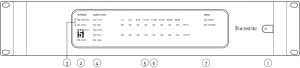
RedNet Control will reflect the status of the RedNet units present in the system, presenting an image representing each hardware unit.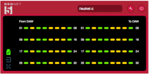
The illustration above shows a RedNet 5 operating in 32-channel Primary mode with signal present on every channel. It has a locked network connection, it is not operating with an External Clock or as Network Leader.
HD32R Only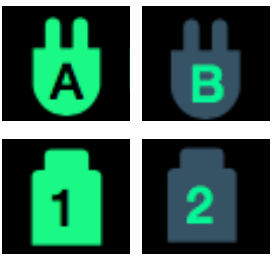 PSUs A & B – Each illuminates if PSU has power input and all DC outputs are present.Network[s] – Each illuminates if a valid connection is present. PSUs A & B – Each illuminates if PSU has power input and all DC outputs are present.Network[s] – Each illuminates if a valid connection is present. |
![]() Locked – Unit is successfully locked to the network (changes to the red cross if not locked).
Locked – Unit is successfully locked to the network (changes to the red cross if not locked).![]() Network Leader – Illuminated indicating that unit is the network leader.
Network Leader – Illuminated indicating that unit is the network leader. External Clock – Green: Illuminates when external clock is selected and locked.Amber: Illuminates when external clock is selected but not locked.Red: Illuminates when external clock is selected but not connected.
Signal Metering
Each input and output channel has a virtual signal indicator. Five different states are represented:
- Black: No signal present
- Dim green: > –126 dBFS
- Green: –42 dBFS
- Amber: –6 dBFS
- Red: 0 dBFS
ID (Identification)
Clicking on the ID icon ![]() will identify the physical device being controlled by flashing its front panel LEDs.
will identify the physical device being controlled by flashing its front panel LEDs.
Tools MenuClicking on the Tools icon ![]() will gain access to the following system settings:Preferred Leader – On/Off state.
will gain access to the following system settings:Preferred Leader – On/Off state.
RedNet Clock Source – Only one can be selected at any time.
- Internal (RedNet 5/HD32R is network leader but running from internal clock)
- Word Clock
- Loop Sync
Word Clock Input Termination – Tick option On/Off. (Terminates word clock input BNC with 75Ω.)
Word Clock Output – One can be selected at any time.
• Network• Network (Base Rate)
Expansion Mode – Tick option On/Off.When enabled, the RedNet 5/HD32R appears to Pro Tools as a single 16 in/16-out interface. This allows another Pro Tools|HD I/O audio interface to be connected to the EXPANSION port. (Check down below)
Hardware Emulation – One can be selected at any time.
- 192 I/O – Select this option when using a Pro Tools|HD software version prior to 8.1.
- HD I/O – Select this option when using Pro Tools|HD software versions 8.1 and above.
APPENDIX
Connector Pinouts
Ethernet Connector
Connector type: RJ-45 receptacleApplies to: Ethernet (Dante)
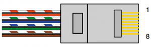
| Pin | Cat 6 Core |
| 12345678 | White + OrangeOrangeWhite + GreenBlueWhite + BlueGreenWhite + BrownBrown |
Pro Tools Interface – RedNet 5Connector type: DigiLink receptacleApplies to: PRIMARY, EXPANSION
Pro Tools Interface – RedNet HD32RConnector type: Mini DigiLink receptacleApplies to: PRIMARY, EXPANSION
BNC ConnectorsConnector type: 75Ω BNC SocketApplies to: WORD CLOCK IN/OUTLOOP SYNC IN/OUT
PERFORMANCE AND SPECIFICATIONS
| Digital Performance | |
| Supported Sample Rates | 44.1 / 48 / 88.2 / 96 / 176.4 / 192 kHz (-4% / -0.1% / +0.1% / +4.167%) at 24 bit |
| Clock Sources | Internal, Word Clock, Loop Sync (leader or follower) or from Dante Network Leader |
| Ext. Word Clock Range | Nominal sample rate ±7.5% |
| Digital Performance | |
| Supported Sample Rates | 44.1 / 48 / 88.2 / 96 / 176.4 / 192 kHz (-4% / -0.1% / +0.1% / +4.167%) at 24 bit |
| Clock Sources | Internal, Word Clock, Loop Sync (leader or follower) or from Dante Network Leader |
| Ext. Word Clock Range | Nominal sample rate ±7.5% |
| Front Panel Indicators | |
| Power [PSU A] | Green LED. Illuminates when an AC input is applied and all DC outputs are present |
| PSU B HD32R only | Green LED. Illuminates when an AC input is applied and all DC outputs are present |
| Network Connected [Primary] | Green LED. Indicates that a network connection is present [on Primary port when in Redundant mode. When in Switched mode, a valid network connection at either Primary or Secondary network port will cause this LED to illuminate] |
| Secondary Network HD32R only | Green LED. Indicates that a network connection is present on secondary port when in redundant mode. Not used in switched mode |
| Network Locked | Green LED. When unit is network follower, shows valid network lock. When network leader, shows unit is locked to indicated clock source. Flashing indicates external clock is selected but not connected |
| Sample Rate | Orange LED for each: 44.1 kHz, 48 kHz, x2, x4 |
| Pull Up/Down | Orange LED. Indicates unit is set to operate on a Dante pull up/down domain |
| Signal Indicators | RedNet 5: 16 Tricolor LEDs, 8 input/8 output indicators. Green Illuminates @ -42dBFS, Amber -6dBFS, Red 0 dBFS.HD32R: 16 Green LEDs, 8 input/8 output indicators. Illuminate @ -126dBFS. |
| RedNet Clock Source HD32R only | Orange LED for each: Internal, Word Clock, Loop Sync and DAW Leader |
| Mode RedNet 5 only | Orange LEDs: Primary and Expansion |
| Network Modes [HD32R Only] | |
| Redundant | Allows unit to connect to two independent networks |
| Switched | Connects both ports to integrated network switch allowing daisy-chaining of device |
| Dimensions | |
| Height | 88mm / 3.5” [44.5mm / 1.75”] 2[1]RU |
| Width | 482.6mm / 19” |
| Depth | 247.5mm / 9.7” [263mm / 10.35”] |
| Weight | |
| Weight | 4.61 [3.9] kg |
| Weight | |
| Weight | 4.61 [3.9] kg |
Focusrite RedNet Warranty and Service
All Focusrite products are built to the highest standards and should provide reliable performance for many years, subject to reasonable care, use, transportation and storage.
Very many of the products returned under warranty are found not to exhibit any fault at all. To avoid unnecessary inconvenience to you in terms of returning the product please contact Focusrite support.
In the event of a Manufacturing Defect becoming evident in a product within 12 months from the date of the original purchase Focusrite will ensure that the product is repaired or replaced free of charge.
A Manufacturing Defect is defined as a defect in the performance of the product as described and published by Focusrite. A Manufacturing Defect does not include damage caused by post-purchase transportation, storage or careless handling, nor damage caused by misuse.
Whilst this warranty is provided by Focusrite the warranty obligations are fulfilled by the distributor responsible for the country in which you purchased the product.
In the event that you need to contact the distributor regarding a warranty issue, or an out-of-warranty chargeable repair, please visit: pro.focusrite.com/rest-of the-world
The distributor will then advise you of the appropriate procedure for resolving the warranty issue.In every case it will be necessary to provide a copy of the original invoice or store receipt to the distributor. In the event that you are unable to provide proof of purchase directly then you should contact the reseller from whom you purchased the product and attempt to obtain proof of purchase from them.
Please do note that if you purchase a Focusrite product outside your country of residence or business you will not be entitled to ask your local Focusrite distributor to honour this limited warranty, although you may request an out-of-warranty chargeable repair.
This limited warranty is offered solely to products purchased from an Authorised Focusrite Reseller (defined as a reseller which has purchased the product directly from Focusrite Audio Engineering Limited in the UK, or one of its Authorised Distributors outside the UK). This Warranty is in addition to your statutory rights in the country of purchase.
Registering Your Product
For access to Dante Virtual Soundcard, please register your product at: www.focusrite.com/register
Customer Support and Unit Servicing
You can contact our dedicated RedNet Customer Support team free of charge:Email: [email protected]Phone (UK): +44 (0)1494 462246Phone (USA): +1 (310) 322-5500
Troubleshooting
If you are experiencing problems with your RedNet 5/HD32R, we recommend that in the first instance, you visit our Support Help Centre at: focusritepro.zendesk.com

References
[xyz-ips snippet=”download-snippet”]