Focusrite Scarlett OctoPre Dynamic
OVERVIEW
Introduction
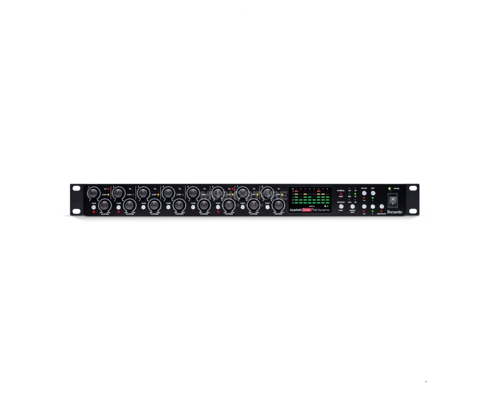
Thank you for purchasing a Scarlett OctoPre Dynamic, an eight channel mic pre expansion unit incorporating high quality Focusrite analogue pre-amplifiers.
The Scarlett OctoPre Dynamic comprises eight natural sounding, low noise preamps with plenty of gain; eight line inputs and two high headroom instrument inputs, coupled with high quality digital conversion to ADAT format. You can now expand your studio set-up or live rig by adding Focusrite quality mic preamps and conversion to any interface with ADAT I/O.
The Scarlett OctoPre Dynamic has both digital and analogue outputs: in addition to dual ADAT optical ports it also provides a balanced line output from each channel, enabling you to connect it directly to any analogue device.
This User Guide provides a detailed explanation of the hardware to help you achieve a thorough understanding of the product’s operational features. We recommend that you take the time to read through the Guide, whether you’re new to professional audio or a more experienced user, so that you are fully aware of all the possibilities the Scarlett OctoPre Dynamic has to offer.
If the User Guide sections do not provide the information you need, be sure to consult https://support.focusrite.com, which contains a comprehensive collection of answers to common technical support queries.
Features
The Scarlett OctoPre Dynamic is an eight-channel pre-amplifier for use with microphone, line and instrument input signals. It converts the inputs into multi-channel, 24-bit digital audio at sample rates up to 192 kHz. The digital outputs are in ADAT format on optical TOSLINK connectors, which can be easily routed to ADAT inputs on your studio recording system, or any other ADAT-equipped interface using optical cables. The Scarlett OctoPre Dynamic can transmit and receive eight channels of audio at sample rates of 44.1, 48, 88.2, or 96 kHz, or four channels at 176.4 or 192 kHz provided, of course, that the interface to which it is connected is able to handle the same number of channels at the sample rate in use.
Each channel includes a switchable, “one-knob” compressor which helps to ensure that the dynamic range of signals in the OctoPre are kept under control as they are routed to your DAW (Digital Audio Workstation).The Scarlett OctoPre Dynamic is an ideal “expansion” unit for adding up to eight more inputs to any audio interface with ADAT I/O.
The Scarlett OctoPre Dynamic is a bidirectional unit: it is also equipped with ADAT format digital inputs, and a balanced analogue output from each channel. It incorporates an ADAT-to-LINE mode, making it a perfect interface for routing tracks from your DAW to an analogue mixing console.
The Scarlett OctoPre Dynamic can be easily synchronised with other digital audio equipment in your studio, either as a slave to an external word clock signal, or by acting as the master clock source itself.
Box Contents
Along with your Scarlett OctoPre Dynamic you should have:
- AC mains cable with IEC connector
- 4 x self-adhesive feet – stick to underside of unit for table-top usePrinted on the inside of the box:
- Getting Started Guide
- Bundle Code for on-line product registration**After registration, you will have access to downloads and licenses for the following software:
- Softube Time and Tone bundle
- Focusrite Red 2 and Red 3 plug-in suite
Hardware Features
Front Panel
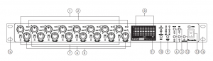
All operational controls and metering for all eight channels are on the front panel.
- Input gain controls 1 to 8 – eight rotary controls: adjust the input gain for the signals in Channels 1 to 8 respectively.
- O/L – each input channel has a red “overload” LED; this illuminates if the signal level causes clipping at the input to the compressor section. If this occurs, reduce the gain so that the LED stays off.
- INST 1 and INST 2 – two latching switches put Inputs 1 and 2 into “Instrument” mode. When INST is selected, the gain range and input impedance are altered (relative to LINE), and the input is made unbalanced. This optimises it for the direct connection of instruments via 2-pole (TS) jack plug. When INST is off, the inputs are suitable for the connection of line level signals. Line level signals may be connected either in balanced form via a 3-pole (TRS) jack or unbalanced, via a 2-pole (TS) jack. Each switch has an adjacent green LED to confirm selection.
- MIC 48V (1-4 & 5-8) – two latching switches, each enabling 48 V phantom power at the XLR contacts of four inputs: Channels 1 to 4 and 5 to 8 respectively. Each switch has an associated red LED indicating that phantom power is selected.
- COMPRESS 1 to 8 – activates the compressor section of each channel, and sets the threshold level. See “Compressor” on page 10 for further details.
- COMP – a yellow LED which illuminates when the compressor section is applying gain reduction. The LED also blinks briefly when the COMPRESS control [5] is moved from its OFF position.
- MORE – a latching switch that increases the ratio of the compressor, thus applying more gain reduction at the same setting of the COMPRESS control. An adjacent red LED confirms selection.
- Input signal level meters: eight LED bargraphs, one per channel. The input signal in each channel is metered post the input gain control and post the compressor section, so you can see the level being sent to the output.
- SAMPLE RATE – a soft switch which steps through the six available sample rate settings, the current rate being indicated by one of the adjacent green LEDs. The sample rate in use is stored in memory so that it is retained when the unit is switched off.
- SYNC – a soft switch which steps through three available digital sync sources (Internal, ADAT or Word Clock), the current source being indicated by one of the adjacent red LEDs. The source in use is stored in memory so that it is retained when the unit is switched off.
 – a green “Locked” LED which illuminates when the unit has locked to the available sync source, indicating that it is ready to use.
- ADAT > LINE – this soft switch modifies the operating mode of the unit. When active, incoming digital audio at the ADAT input ports is converted to analogue and made available at the rear panel LINE OUTPUT connectors. The adjacent red LED confirms that this mode is active. In this mode, the analogue inputs (Channels 1 to 8) remain routed to the ADAT digital outputs. The mode in use is stored in memory so that it is retained when the unit is switched off.
- POWER – AC power switch and green LED.
- Rack ears for mounting the Scarlett OctoPre Dynamic in a standard 19” equipment rack.
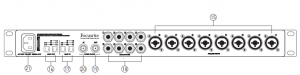
Rear Panel
All inputs and outputs are on the Scarlett OctoPre Dynamic’s rear panel.
- MIC/LINE INPUTS 1 to 8 – 8 x “Combo XLR” sockets – connect microphones using XLR connectors or line level signals using ¼” jacks. Either TRS (balanced) or TS (unbalanced) jack plugs can be used for line level signals. Note that Channels 1 and 2 also have INST mode for the direct connection of instruments (e.g., guitar), but are otherwise identical to those for Channels 3 to 8. INST mode is selected by the INST switches [3].
- ADAT OUT – two TOSLINK connectors providing the digital outputs of the unit. Utilisation of the two connectors is sample rate-dependent, as follows:
Sample Rate
OUTPUT 1 (RH port*) OUTPUT 2 (LH port*)
44.1/48 kHz
Channels 1 to 8 (Not Used) 88.2/96 kHz
Channels 1 to 4 Channels 5 to 8
176.4/192 kHz
Channels 1 & 2 Channels 3 & 4
* As viewed looking at rear panel
- ADAT IN – two TOSLINK connectors providing the digital inputs to the unit when used in the ADAT > LINE mode. In ADAT > LINE mode, signals at the ADAT input(s) will be fed to the analogue line outputs following D-to-A conversion. Utilisation of the two connectors is sample rate dependent, as follows:
Sample Rate
INPUT 1 (RH port*) INPUT 2 (LH port*)
44.1/48 kHz
Channels 1 to 8 (Not Used)
88.2/96 kHz
Channels 1 to 4 Channels 5 to 8
176.4/192 kHz
Channels 1 & 2 Channels 3 & 4
* As viewed looking at rear panel
- . LINE OUTPUTS 1 to 8 – eight balanced analogue line outputs on ¼” 3 pole (TRS) jack sockets. These connectors are always active, and normally carry the outputs of Channels 1 to 8, enabling the Scarlett OctoPre Dynamic to be used as a stand-alone, high quality 8-channel analogue mic pre. In ADAT > LINE mode, the connectors carry the signals applied at the ADAT IN ports [17].
- WORD CLOCK OUT – a BNC connector carrying the Scarlett OctoPre Dynamic’s word clock signal; this may be used to synchronise other digital audio equipment forming part of the recording system. The source of sample clock synchronisation is selected by the SYNC switch [10].
- WORD CLOCK IN – a BNC connector for the connection of an external word clock signal; select by setting SYNC to WORD. Use this input if you have a master reference clock which provides synchronisation for all the digital audio devices in your studio.
- AC mains – standard IEC receptacle. The Scarlett OctoPre Dynamic is fitted with a “Universal” power supply, and will run from any AC mains voltage from 100 to 240 V, at 50 or 60 Hz.
USING THE SCARLETT OCTOPRE DYNAMIC
Combo Inputs
All eight of the analogue inputs use “Combo XLR” connectors. These can accept male XLR connectors, TS (unbalanced) ¼” jacks or TRS (balanced) ¼” jacks.
When an XLR connector is used, the pre-amp automatically configures gain and impedance to receive microphone level signals. If a ¼” connector is used, the pre-amp is set to accept balanced or unbalanced line level signals. When INST mode is selected (on Channels 1 or 2), the ¼” input reconfigures again to optimise for an unbalanced, high impedance signal.
Phantom Power
The two 48V switches apply 48 V phantom power to Mic inputs 1 to 4 and 5 to 8 respectively. Phantom power is required by most condenser (capacitor) microphones. Phantom power is only applied to the XLR contacts of the Combo connectors: thus if a group of 4 inputs is being used for both mic and line (or instrument) level signals, phantom power is only applied to the microphones.
Dynamic microphones do not require phantom power, but most will operate normally with phantom power supplied. Passive ribbon microphones do not require phantom power and may be damaged if supplied with phantom power
If you are unsure about a microphone DO NOT apply phantom power without checking the manufacturer’s specifications first.
Pre-amp Gain
The gain of each channel should be adjusted to suit the incoming level; louder sources will need less gain than quieter ones. Always use the LED meters to check the signal level on each channel. Start with the Gain control set to minimum. Play (or sing) at the loudest level that is likely to be reached during the song, and gradually increase the gain until the meter shows orange (-3 dB).
Then lower the gain by a few dB. This should ensure that the signal level is unlikely to ever reach red (0 dB) and overload the A-to-D converter, which would result in distortion.
Note that the high headroom pre-amplifier design used in the Scarlett range means that a switchable Pad is unnecessary. (See “Performance Specifications” on page 19 for input sensitivity specifications.)The red O/L LED should never illuminate; if it does, the gain is set too high.
Compressor
Turning a channel’s COMPRESS control clockwise from its OFF position activates the channel’s compressor. As the control is moved from the OFF position, the yellow COMP LED will light briefly to confirm that the compressor is now active. As it is rotated clockwise, the compression threshold is progressively reduced, resulting in increasingly heavy compression. The yellow COMP LED will illuminate when compression is being applied to the signal, which will be the case whenever the signal level exceeds the threshold.
Pressing the MORE button increases the compression ratio, thereby applying more compression to the signal for the same setting of COMPRESS.
Compressor – additional information
On the Scarlett OctoPre Dynamic, the COMPRESS control is essentially a combined Threshold and Gain Make-up control: as the threshold is reduced, causing more of the signal to be compressed, the compressor’s overall gain (often referred to as “Make-up Gain”) is increased, raising the signal level at the output to match that at the input.
In both modes the attack time is 1.2 ms and the release time is 28 ms
The two graphs below show the compression characteristics in “Normal” and “More” modes respectively. The curves include the effect of the make-up gain on the overall signal level.
The four curves represent:
- OFF – Compressor Off
- MIN – COMPRESS control set to minimum
- MID – COMPRESS control set to 12 o’clock
- MAX – COMPRESS control set to MAX
Normal Mode
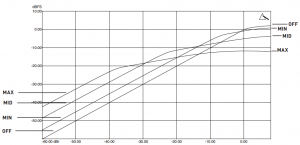 In Normal mode (MORE mode off), the compression ratio is 2:1.
More Mode
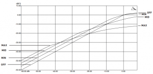 In More mode (MORE button on) the compression ratio is increased to 4:1
Line Outputs
By connecting the line outputs of the Scarlett OctoPre Dynamic to the analogue line inputs of a mixing console (or any other device), the unit can be used either as a purely analogue, 8-channel microphone pre-amplifier, or as an analogue “break-out box” for ADAT signals when in ADAT > LINE mode.
The line outputs are balanced: for a balanced connection use ¼” 3-pole (TRS) jacks, or ¼” 2-pole (TS) jacks for an unbalanced connection.
The maximum output signal level is +16 dBu (balanced), or +10 dBu (unbalanced).
Digital Outputs
Use the ADAT OUT optical port(s) [16] to connect the Scarlett OctoPre Dynamic to the ADAT input(s) of an audio device using TOSLINK optical cable(s).
The right-hand port (as viewed from the rear of the unit) can transmit eight channels of audio at 44.1 kHz or 48 kHz sample rate via a single optical cable.At 88.2 kHz or 96 kHz sample rates, each port can transmit four channels of audio. The right-hand port carries Channels 1 to 4, the left-hand port carries Channels 5 to 8; thus two TOSLINK cables are required to transmit all eight channels.
At 176.4 kHz or 192 kHz sample rates, each port can transmit two channels of audio. The right-hand port carries Channels 1 and 2, the left-hand port carries Channels 3 and 4. The Scarlett OctoPre
Dynamic is restricted to four channels of digital audio at these sample rates; the outputs of Channels 5 to 8 are not available via the ADAT ports.Use the SAMPLE RATE switch [9] to select the desired sample rate frequency. It is essential that the sample rate selected on the Scarlett OctoPre Dynamic matches the sample rate set on the receiving digital device.
Digital Inputs
Use the ADAT IN optical port(s) [17] if you need to convert digital audio (e.g., the output of a DAW) to analogue, using the Scarlett OctoPre Dynamic’s ADAT > LINE mode.
The right-hand port (as viewed from the rear of the unit) can receive eight channels of audio at 44.1 kHz or 48 kHz sample rate via a single optical cable.At 88.2 kHz or 96 kHz sample rates, each port can receive four channels of audio. The right-hand port carries Channels 1 to 4, the left-hand port carries Channels 5 to 8; thus two TOSLINK cables are required to receive all eight channels.
At 176.4 kHz or 192 kHz sample rates, each port can receive two channels of audio. The right-hand port carries Channels 1 and 2, the left-hand port carries Channels 3 and 4. The Scarlett OctoPre Dynamic is restricted to four channels of digital audio at these sample rates.
Use the SAMPLE RATE switch [9] to select the desired frequency. It is essential that the sample rate selected on the Scarlett OctoPre Dynamic matches the sample rate set on the transmitting digital device.
Digital Synchronisation
A number of synchronisation options are available:
Scarlett OctoPre Dynamic as Clock Source Master via ADAT:Connect the Scarlett OctoPre Dynamic to the receiving digital device via the ADAT OUT port(s) and ensure that the receiving device is set to source its clock from its ADAT input, and also that the sample rates on both devices match.
On the OctoPre, SYNC should be set to INTERNAL and the ![]() LED will illuminate
LED will illuminate
Scarlett OctoPre Dynamic as Clock Source Master via word clock:An alternative method to the above is to sync the receiving device to the Scarlett OctoPre Dynamic’s WORD CLOCK OUT using a BNC cable. In this scenario, the receiving device’s sync source will need to be set to its external word clock input.
Scarlett OctoPre Dynamic as Clock Source Slave via ADAT:Connect the Scarlett OctoPre Dynamic’s ADAT OUT port(s) to the receiving digital device’s ADAT input. Connect the digital device’s ADAT output to one of the Scarlett OctoPre Dynamic’s ADAT IN ports. On the OctoPre, SYNC should be set to ADAT and the ![]() LED will illuminate. Also ensure that the sample rates on both devices are matched.
LED will illuminate. Also ensure that the sample rates on both devices are matched.
Scarlett OctoPre Dynamic as Clock Source Slave via word clock:Connect the Scarlett OctoPre Dynamic to the receiving digital device via the ADAT OUT port(s) and connect a BNC cable from the digital device’s word clock output to the OctoPre’s WORD CLOCK IN connector, also ensuring that the sample rates on all devices match.
ADAT-to-Line mode
Selecting ADAT > LINE mode ([12] on the front panel) reassigns the eight sources for the analogue LINE OUTPUTS [18]. In normal operation, the outputs of the mic pre-amplifier channels are available at these connectors; in ADAT > LINE mode, the connectors are fed with the ADAT digital signals at the ADAT IN port(s), following D-to-A conversion.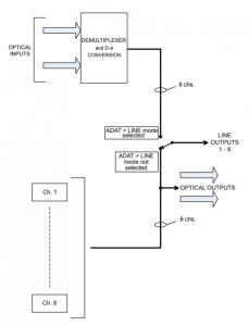 This mode enables the Scarlett OctoPre Dynamic to be used to connect an 8-channal ADAT format output (from a DAW, for example) to a set of analogue inputs, typically the channels of an analogue mixing console, to permit such a mixer to be used to mix down DAW tracks.
When ADAT > LINE mode is enabled, the eight microphone pre-amplifiers are still operational, and their outputs remain available at the ADAT OUT ports
EXAMPLE SETUPS
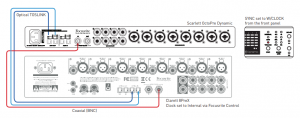
Scarlett OctoPre Dynamic with audio interface: OctoPre as clock source Master
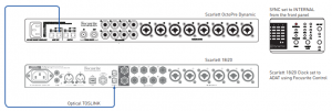 Here ADAT OUT on the Scarlett OctoPre Dynamic is connected to OPTICAL IN on a Scarlett 18i20 audio interface with a single optical cable. Both units are running at 44.1 kHz sample rate. The OctoPre’s clock source is set to INTERNAL, and the 18i20 is synchronised to it because its clock source is set to ADAT (via Focusrite Control).
This setup would, for example, enable up to 16 mic or line sources to be recorded in a DAW simultaneously, and would thus be ideal for recording a live band. Eight of the sources (those connected to the OctoPre) could benefit from the internal dynamics if necessary and have compression applied to control the dynamic range of the signals.
The setup would also be appropriate for any other audio interface which has an ADAT input.
Scarlett OctoPre Dynamic with audio interface: audio interface as clock source Master
Here ADAT OUT on the Scarlett OctoPre Dynamic is connected to OPTICAL IN on a Scarlett 18i20 audio interface with a single optical cable. Both units are running at 44.1kHz sample rate. The OctoPre’s WORD CLOCK IN input is connected to WORD CLOCK OUT on the Scarlett 18i20 with a BNC cable and the OctoPre’s clock source is set to W/CLOCK. The 18i20’s clock source is set to INTERNAL (via Focusrite Control), thus making it the sync master.
The setup would also be appropriate for any other audio interface which has an ADAT input and a word clock output.
Scarlett OctoPre Dynamic in ADAT > Line mode
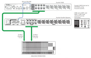
This example shows how to connect a greater number of DAW tracks to an analogue mixing desk for mixdown. The 10 analogue outputs of a Scarlett 18i20 interface are connected to desk Channels 1 to 10. Its OPTICAL OUT port is connected to an ADAT IN port of a Scarlett OctoPre Dynamic with ADAT > LINE mode selected. The OctoPre’s LINE OUTPUTS are then connected to Channels 11 to 18 of the desk.
The Scarlett 18i20 would normally be the sync master in this situation, so its clock source is set to INTERNAL (via Focusrite Control). The clock source on the Scarlett OctoPre Dynamic is set to ADAT,so it is synchronised to the 18i20 via the ADAT optical connection.
The above channel counts are applicable at 44.1/48 kHz sample rate; four channels of audio could be transferred from the 18i20 to the OctoPre at 88.2/96 kHz.
Scarlett OctoPre Dynamic with audio interface – SMUX-II and SMUX-IV modes
 This example shows a similar setup to Example 2, but using a Focusrite Clarett 8PreX allows operation at a sample rate of 96 kHz (“SMUX-II” mode). Both units must be set to 96kHz; two optical cables are used, carrying four channels of audio each. The Clarett 8PreX is the sync master.
This setup is also applicable with 192 kHz sample rate (“SMUX-IV” mode); each optical cable will then carry two channels of audio.
Scarlett OctoPre Dynamic with analogue mixing desk
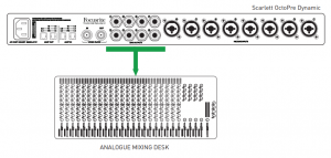
This setup uses the Scarlett OctoPre Dynamic’s mic pre-amplifiers and compressors to provide a high quality “front end” for an analogue mixing desk. Use a pre-made loom to connect the OctoPre’s LINE OUTPUTS socket to eight line inputs on the mixing desk; this will need eight ¼” TRS jacks on one end and eight connectors appropriate to the desk’s line inputs on the other. If the desk’s line inputs are unbalanced, a loom with TS jacks at the OctoPre end will be suitable.
This setup would also be appropriate to use the OctoPre as an input stage with any type of 8-channel analogue device.
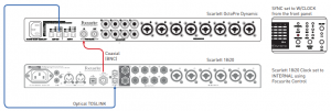
Scarlett OctoPre Dynamic with analogue mixing desk and digital record/backup
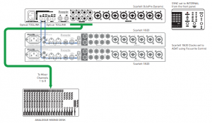 This example shows how the setup in Example 5 can be extended to add simultaneous digital recording, with or without secondary backup.
Because the Scarlett OctoPre Dynamic’s ADAT OUT ports are always active, you can record the performance on a DAW (or other recording device) with an ADAT interface. The example shows two Scarlett 18i20s: the ADAT IN port of each would be connected to the two ADAT OUT ports of the OctoPre, to provide 8-track recording (on the first) and a simultaneous 8-track backup on the second, at sample rates of 44.1 or 48 kHz.
8-track recording could still be achieved at 88.2 or 96 kHz, although each Scarlett 18i20 would provide 4 channels to the DAW; backup would not be possible.
SCARLETT OCTOPRE DYNAMIC TECHNICAL SPECIFICATIONS
Performance Specifications
(All performance figures are measured to the AES17 standard)
| Sample Rates | |
| Supported sample rates | 44.1 kHz, 48 kHz, 88.2 kHz, 96 kHz, 176.4 kHz & 192 kHz |
| Microphone Inputs | |
| Frequency Response | 20 Hz to 20 kHz, +0.5/-1.5 dB |
| Dynamic Range | 107 dB (A-weighted) |
| THD+N | <0.002% |
| Noise EIN | –127 dBu |
| Maximum input level | +13 dBu |
| Gain Range | 50 dB |
| Input Impedance | 3 kΩ |
| Line Inputs | |
| Frequency Response | 20 Hz to 20 kHz, +0.5/-1.5 dB |
| Dynamic Range | 107 dB (A-weighted) |
| THD+N | <0.002% |
| Maximum input level | +21 dBu |
| Gain Range | 50 dB |
| Input Impedance | 64 kΩ |
| Instrument Inputs | |
| Frequency Response | 20 Hz to 20 kHz, +0.5/-1.5 dB |
| Dynamic Range | 107 dB (A-weighted) |
| THD+N | <0.015% |
| Maximum input level | +13 dBu |
| Gain Range | 50 dB |
| Input Impedance | 1 MΩ |
| Line & Monitor Outputs | |
| Dynamic Range (Line outputs) | 109 dB (A-weighted) |
| THD+N | <0.001% |
| Maximum Output Level (0 dBFS) | +16 dBu |
| Output Impedance | 136 Ω (Balanced) – for units with serial number ≤ W960065003383 |
| 576 Ω (Balanced) – for units with serial number > W960065003383 |
* As a result of a component change in the Scarlett OctoPre and Scarlett OctoPre Dynamic designs, some units have a higher output impedance. This change has been fully tested and has no impact on the audio performance. Please see the table above for the impedance of Scarlett OctoPre by serial number range:
Physical and Electrical Characteristics
| Analogue Inputs | |
| Connectors | “Combo XLR” sockets on rear panel; for Line use ¼” TRS jack, for Inst use ¼” TS jack. |
| Mic/Line switching | Automatic |
| Line/Instrument switching (Chs. 1 & 2 only) | via front 2 x front panel switches |
| Phantom power | +48 V, switchable Chs. 1-4, 5-8 in groups |
| Outputs | |
| Analogue outputs | 8 x balanced, on rear panel ¼” TRS jack sockets |
| Other I/O | |
|
ADAT I/O |
4 x TOSLINK optical connectors:
8 channels at 44.1/48 kHz (RH port*) 8 channels at 88.2/96 kHz (Chs 1-4 RH port*, 5-8 LH port*) 4 channels at 176.2/192 kHz (Chs 1 & 2 RH port*, 3 & 4 LH port*) |
| Word clock output | 2.5 V (correctly terminated with 75 ohms); BNC connector |
| Word clock input | BNC connector: 5 V into 75 ohms |
| Weight and Dimensions | |
| W x D x H | 482 mm x 44.5 mm x 286 mm
19” x 1.75” x 11.26” |
| Weight | 3.37 kg
7.43 lbs |
* ADAT ports as viewed from rear of unit.
TROUBLESHOOTING
For all troubleshooting queries, please visit the Focusrite Answer base at https://support.focusrite.com where you will find articles covering numerous troubleshooting examples.
COPYRIGHT AND LEGAL NOTICES
Focusrite is a registered trade mark and Scarlett OctoPre Dynamic is a trade mark of Focusrite Audio Engineering Limited.All other trade marks and trade names are the property of their respective owners. 2016 © Focusrite Audio Engineering Limited. All rights reserved.

References
[xyz-ips snippet=”download-snippet”]