FoMaKo KC-601 Conference PTZ Camera Control Keyboard User Manual
(V1.1)
Statement:
The descriptions in this manual may differ from the version you are using. If you are having trouble during using this manual, please contact our technical support for assistance. The contents of this manual will be updated, and our company reserves the right to leave it without notice.
Precautions
The controller is an indispensable device in the integrated video conferencing system, providing full control of all front-end cameras, pan/tilt and motorized lenses. There are usually many numeric keys and function keys on the controller. The numeric keys are used to select the camera or decoder address, and the function keys are used to perform various control operations on the selected front-end device. An LCD liquid crystal display is provided on the control keyboard for displaying control commands or working states of various monitoring programs in the system. One system use one controller for remote control of the entire video conferencing system.
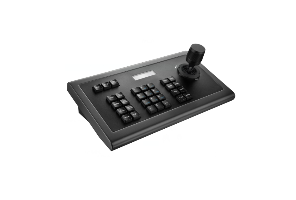
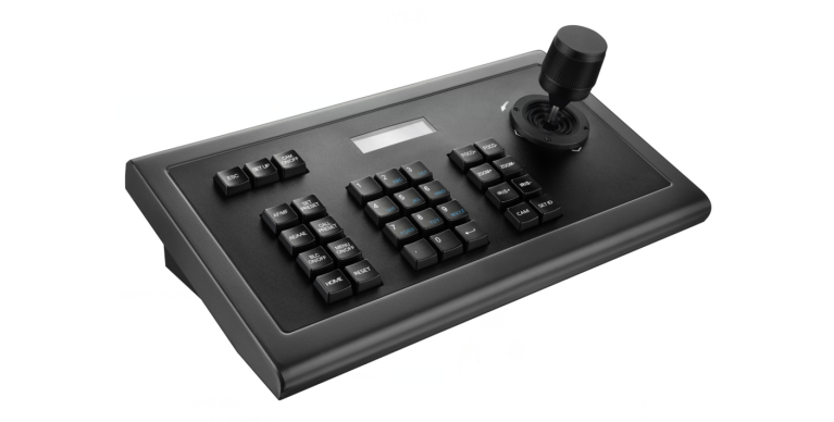
1. Product Overview
1.1 Product Features
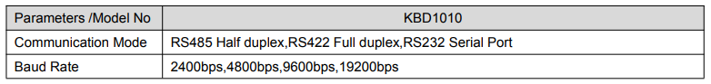
- Adopt RS485, RS422, RS232 multiple interface control signals, max up to 255 cameras
- Support PELCO-D,PELCO-P and VISCA Control protocol
- Metal housing, computer keyboard button design
- Adopt 3D joystick to control the camera speed.
- Control camera rotation, zoom, aperture, focus and other camera parameter settings
- English & Chinese LCD display, displaying the real-time working status of the decoder and matrix
- With button sound prompt function
- Unique control code learning function allows customers to modify control code commands by themselves
- Any device connected with RS485 cable can be set with different protocols and baud rates separately.
- RS422 communication interface has the over-current protection ability to recover from short circuit.
- The max communication distance is up to 1200M(0.5MM Twisted Pair Cable).
1.2 Technical Parameters

1.3 Precautions
- LCD Screen is fragile, do not squeeze or leave under harsh light for too long.
- The joystick rocker is fragile. Do use the original package or properly packaged before shipment back.
- Make it work in the place with favourite temperature and humidity.
- Strictly follow the manual for correct connection.
1.4 Accessories List


【ESC】Exit and back to former menu.
【SETUP】Parameter setting button:Long press 3S to enter the KBD parameter setting status
【CAM ON/OFF】Camera power on/off button
【AF/MF】Auto focus / manual focus:
Manual focus need to work together with [FOCUS]+ or [FOCUS-] button.
【SET PRESET】Presets setting button, working together with number keys and the [ENTER] button.
【CALL PRESET】Call presets button, working with the number keys and the [ENTER] button.
【AE/AAE】Auto Aperture / Aperture priority button, working together with 【OPEN】and【CLOSE】 buttons.
【BLC ON/OFF】: Back light compensation ON/OFF button
【MENU ON/OFF】: MENU ON/OFF button
【HOME】:HOME button
【RESET】: Pan/tilt reset button
【CLR】Clear button: clear the current inputs.
【0】~【9】Number keys:0,1,2,3,4,5,6,7,8,9.
【ENTER】Confirmation key: Confirm the current inputs.
【NEAR】Focus in: manually focus in to make far distance objects clearer
【FAR】Focus out: manually focus out to make near distance objects clearer
【TELE】Narrow-angle button/ Zoom-in button: increase lens magnification, reduce the lens field of view, enlarge the monitor target.
【WIDE】Wide-angle button/Zoom out button: reduce lens magnification, expand lens field of view and monitoring range
【OPEN】Aperture plus button: Increase manual aperture. When the aperture is at its maximum, the LCD screen is displayed in full white. When the camera menu mode is turned on, the next level menu is entered.
【CLOSE】Aperture minus button: Reduce manual aperture . When the aperture is at its minimum, the LCD screen is displayed as black. When the camera menu mode is turned on, the menu is returned to the previous menu.
【CAM】Address selection button: Select the address of the control device (decoder or camera) , it needs to use together with the number keys and [ENTER] button
【SET ID】Set ID button: long press 3s to set the cascade camera protocol address.
2.2 LCD screen display
All button operations will be displayed on LCD screen. It would enter into power saving mode(with darkest light), with initializing status displayed if no operation for 30 seconds.
2.3 Joystick Control
(Clockwise/ Counterclockwise rotation only available for 3D design)

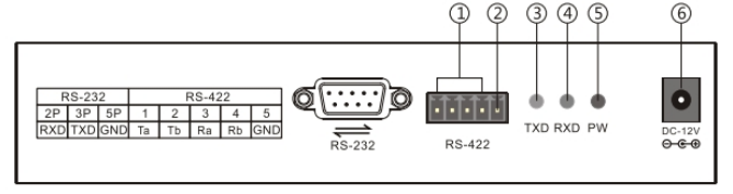
2.4 Back Panel Interfaces
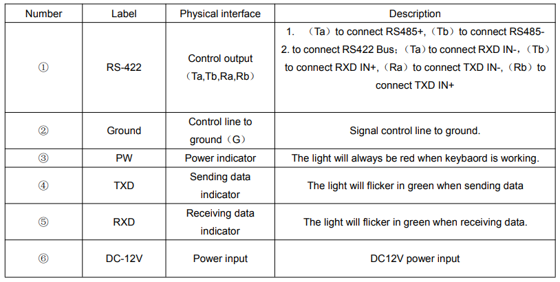
Back Panel Details: 1x 5PIN crimping terminal interface,1 x RS232 interface,1xDC-12V power socket,3 x indicator lights as picture below:
2.5 Functional number description
3. Parameter Setting and Query
3.1 PTZ Setup
E.g. With address code 28, steps to change to Pelco-P protocol and baud rate to 9600 are as follows: Press【SETUP】button for 3 seconds under normal working mode, it displays as follows:
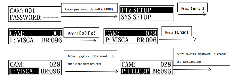
Then press 【ENTER】,there will be a 1sec beep sound when setting done. Press【ESC】 3 times to back to normal working mode.
Note: Steps to set all devices to be with same protocol and baud rate are as follows:
Enter into the setup page  and choose the corresponding protocol and baud rate. Then all devices within 0-255 addresses are set with the same protocol and baud rate.
3.2 System Setup
System setup includes: password setting, Restore factory setting, Indicate sound switch setting, Keyboard ID and Keyboard lock switch setting.
Here shows the steps to restore factory setting and set keyboard lock switch.
3.2.1 Password Setting
Press【SETUP】button for 3 seconds under working mode, it displays as follows :

Then input the new password again,press【ENTER】,there will be a 1sec beep sound when setting done. Press【ESC】twice to back to normal working mode.
3.2.2 Restore Factory Setting
Press【SETUP】button for 3 seconds under working mode, it displays as follows :
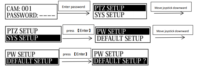
Press 【ENTER】,there will be a 1sec beep sound when setting done.
Press 【ESC】 twice to back to normal working mode.
3.3 Keyboard Parameter Setting Frame

3.4 keyboard parameter query


4.Typical wiring diagram
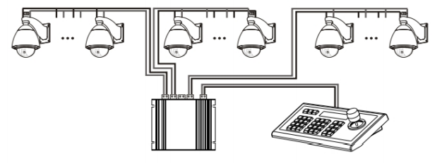
4.1 Typical wiring diagram
Connection with surveillance dome camera
Connection with video conference camera
- control output:connect camera RS485+ with keyboard Ta, RS485- with Tb.
- Deputy control device:either RS485 output from DVR or keyboard is available.
4.2 Connection Analysis
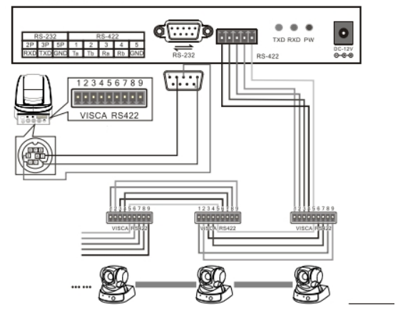
4.2.1 connection between keyboard and camera
With RS422 bus connection way, the keyboard third pin (Ra) is connected with the camera third pin TXD IN- , the keyboard fourth pin (Rb) with the camera fourth pin TXD IN+ , the keyboard first pin(Ta ) with the camera first pin RXD IN-, the keyboard second pin (Tb)with the camera second pin RXD IN +.
KBD CAMERARa<········>TXD IN-Rb<········>TXD IN+Ta<········>RXD IN-Tb<········>RXD IN+
With RS232 connection way, the KBD(10pin connecting terminal) first pin RXD is connected with the third pin TXD of camera RS232 port, the KBD second pin TXD with the camera fifth RXD, the KBD third GND with the camera forth pin GND.(It is also available to connect camera with the standard RS232 port on the KBD.)
KBD CAMERARXD<········>TXDTXD<········>RXDGND<········>RXD
The camera can be controlled by any connection way mentioned above.
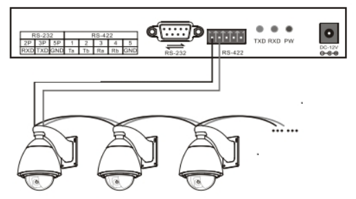
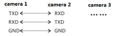
4.2.2 Connection between cameras
With the RS422 bus cascade connection, the output of camera 1 is connected with the input of camera 2, and the output of camera 2 is connected with the input of camera 3, and so on so forth. As shown below:

The RS232 cascade connection way is almost the same as that of RS422. The output of camera 1 is connected with the input of camera 2, the output of camera 2 is connected with the input of camera 3, and so on so forth.
5. Appendix
5.1 RS485 bus introduction:
RS485 bus, RS is the abbreviation of English “recommended standard”, 485 is the identification number. The RS485 serial bus is widely used in applications where the communication distance ranges between dozens of meters to 1km more. RS485 uses balanced transmitting and split receiving, so it has the ability to reject common mode interference. In addition to the high sensitivity of the bus transceiver, it can detect voltages as low as 200mV, so the transmitted signal can be recovered beyond the kilometers away. As RS485 adopts half-duplex working mode, and only one point is allowed to be under sending status any time, the transmitting circuit must be controlled by the enable signal. RS485 is very convenient for multi-point interconnection, which help save many signal lines. RS485 can be used to make a distributed system, which allows up to 128 drivers and 128 receivers to be connected in parallel, depending on the chip used by the driver and receiver, and the bus drive capability is limited by the weakest one. However, in practical applications we can extend it with the RS485 distributor
5.2 Transmission distance:
When a 0.56mm (24AWG) twisted pair cable is used as the communication cable,the theoretical value pf the maximum transmission distance varies with different baud rate: 1800 meters can be transmitted when the baud rate is 2400 bps, and 600 meters under 19200 bps. When using a thinner communication cable, or using the product in an environment with strong electromagnetic interference, or when too many devices are connected with the bus, the maximum transmission distance will be shortened accordingly, or the maximum distance is longer.
5.3 Connection method and terminating resistor
The RS485 industrial bus standard requires daisy chain connection between devices. The two ends must be connected with a 120Ω termination resistor. The two balance distances must be within 7m.

5.4 Problems in Actual Application
The star link mode will always be used in actual constructions, requiring the terminating resistor to be linked with the two devices in the farthest distance. But it does not meet the requirements of the RS485 industry standards. When the distance between each device are too long, signal reflection and anti-interference ability reducing would frequently happen, which will decrease the reliability of the control signal. It means the camera will not be under control or under control intermittently. In this case, the application of RS485 distributor is recommended, which can effectively convert the star link mode to one qualified by the RS485 industry standards. It will help avoid problems and improve the communication reliability
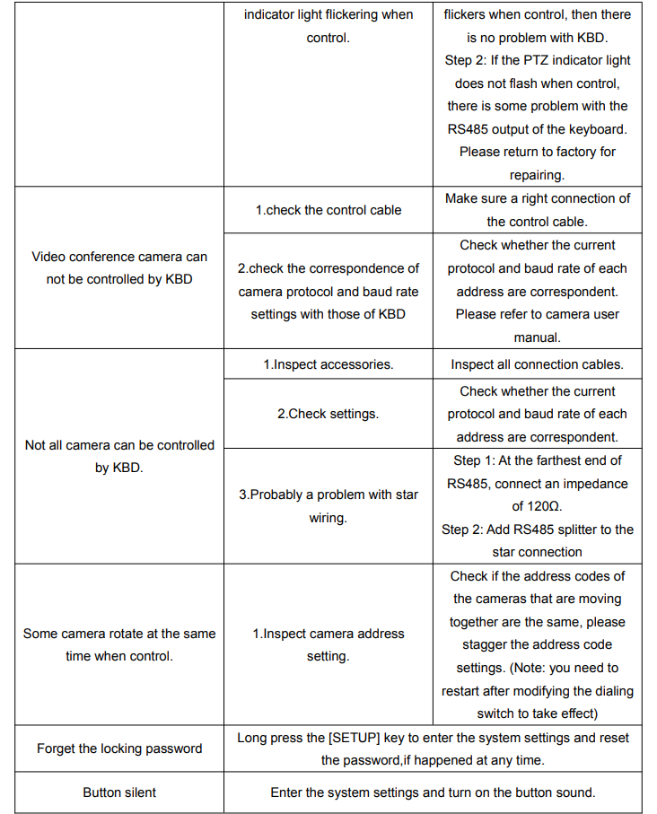
6. Trouble shootings

Copyright Statement
All the contents in this manual and its copyright are owned by the company. No one is allowed to imitate, copy, or translate this manual without the company’s permission. This manual contains no guarantee, standpoint expression or other implies in any form. Product specification and information in this manual is for reference only and subject to change without notice. All rights reserved. No reproducing is allowed without acknowledgement.
[xyz-ips snippet=”download-snippet”]