![]()
USER GUIDE
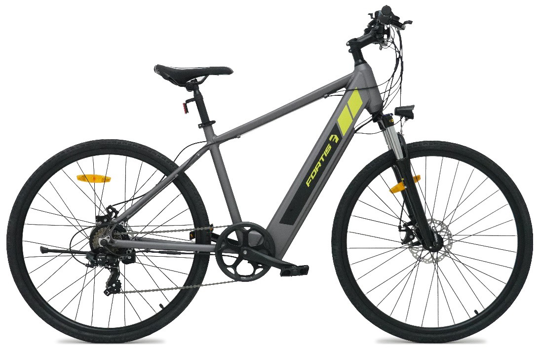
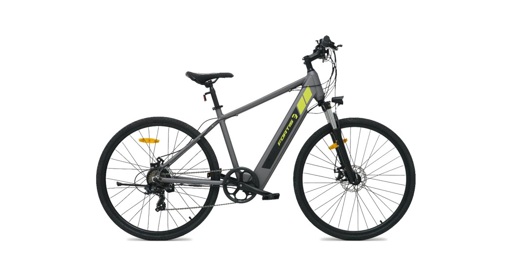
700C HYBRID COMMUTERELECTRIC MOUNTAIN BIKEFS27HCMEBKA
SAFETY & WARNINGS
Electric Assisted Bike RegulationsThe EN 15194 EU standard or EPAC (Electric Power Assisted Cycle) conforms to the following characteristics for electric power-assisted bikes:
 Motor assistance only starts when the cyclist pedals.
- The assistance cuts out as soon as the cyclist stops pedaling.
- The assistance cuts out as soon as the speed exceeds 25km/h.
 Motor assistance only starts when the cyclist pedals.
Adherence to this standard enables the use of electric bikes in the same conditions as any other bicycle, particularly on bicycle paths and bicycle-specific lanes.
Recommendation Before First Ride
- Before first use, please double-check the function of all the parts of your electric bike. If you have any doubts or if you detect a problem, please contact your authorized dealer or technical service department.
- If you lend your bicycle to a third party, please give them this instruction manual with the bicycle and request that they read it before the first ride.
- Respect local and national road traffic regulations.
- For your safety, it is highly recommended that you wear a certified helmet.
- When used during heavy rain, snow, in slippery conditions, or in the case of low visibility, be careful and adjust your speed.
- At night, ride using the lights.
- Trying to repair anything that implies removing technical or electrical components is strongly advised against. If necessary, please contact your dealer’s after-sales service.
- The manufacturer declines any responsibility due to overloading or items that are not correctly attached to the baggage rack.
- Using high pressured water jets to clean the bike is strongly advised against.
- Check the battery level before use. You must fully charge it before first use.
- In order to extend battery performance and lifespan, do not half charge, and adapt your ride length to battery level.
- The batteries’ life will vary depending on where you ride it (inclines will reduce power rapidly) and how you ride (assistance mode chosen). The greater the assistance used, the more you’ll use the battery and the shorter it will last. Do not forget that your bike has gears; remember to use them accordingly relative to riding conditions in order to extend battery life. The amount of weight carried also impacts on battery life span. Extreme low temperatures can also impact the battery life span.
- It is recommended that you charge the battery at least every 2 months when the bike is not used; during winter, for example.
- Store the battery in a dry place after having completely recharged it. Avoid extreme temperatures (low and high) as they can damage the battery. Optimal operating range: -10°C to 35°C.
Cleaning Your Pedal-Assisted BikeUse a dedicated bicycle shampoo or soap with hot water to clean your bike (and different components like the wheels, hubs, rims, brakes, and pedals). Rinse well with clean water before use. Do not use high-pressure water jets to clean your bike, especially on the electrical components (such as the battery), as it may result in short-circuiting or system malfunctions. Use a damp cloth with neutral detergent to clean the bike frame. Do not use any detergents or cleaning liquids liable to deteriorate the frame or components.
WarningDo not ride after taking drugs or alcohol or while using medication that might make you drowsy. Pedal-assisted bicycles are not designed for 2 people. Do not ride double as these bicycles are not designed to carry the additional load of a second rider. Do not put batteries in normal waste bins. Dispose of used batteries in a certified recycling facility. Do not over lubricate; if oil contacts the wheel rim, brake pads, or brake disks, this will result in loss of braking performance and an increase in stopping distances. This could potentially cause loss of control, accidents, and injury.
TransportIt is highly recommended that you do not overload your pedal-assisted bicycle as you could damage the electrical components or cause malfunctions, like overheating of the battery or the motor. Do not store the battery in excessively hot or cold places.
- Maximum transport weight on the bicycle must not exceed 75kg.
- Regularly check battery brackets and mountings.
- Please wear a helmet when riding your pedal-assisted bicycle.
- If a rack is not already fitted to your bicycle, please do not attempt to fit one yourself.
- Do not carry anything on the rack that might hide lights or reflectors.
SecurityAll the components and parts of your bicycle are subject to normal wear and fatigue. Keep a close eye on any change in the shape or color of a component, or traces of oxidation (rust) on your bicycle. If this occurs, do not use the product until the component has been replaced.
OVERVIEW
Recommendations and Component Control before UseBefore using your bicycle for the first time, you must check that all adjustments have been correctly made.
- Check that the front and rear brakes work; check brake pads for wear.
- Check the cables and sheaths, and that the hydraulic system functions correctly.
Wheels and Tires
- Check tires are inflated to the pressure indicated (either in Bar or Psi) on the tire sidewall.
- Check that the tires are in good condition and are free from cuts or bulges.
- Check the state of wheel rims and ensure that spokes are correctly tightened.
- Check that the wheels are correctly fitted to the bicycle, either by a quick-release system or nuts.
Safety Warning: If a wheel rim or spokes are damaged, immediately replace the wheel.
Steering
- Check that the handlebar and stem are correctly tightened and that they are in line with the wheel and the fork.
- Check that the steering clamp is correctly tightened and adjusted in the right direction.
Frame and Fork
- Check that the frame shows no signs of fatigue or damage and that the fork works correctly.
Chain
- Make sure that the chain is at the correct tension.
- Make sure that it is clean, rust-free, and properly oiled. Use adapted lubrication for use in extreme weather conditions.
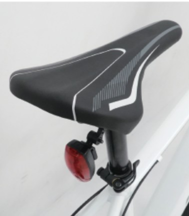
Seat and Seat-postMake sure that seat and seat-post are correctly tightened and positioned.
Bearings
- Check that all bearings are properly adjusted and lubricate if needed. Make sure that they are not too loose or that they have seized up. Check steering bearings, wheel bearings, pedal bearings, and bottom bracket bearings.
Crankset and Pedals
- Make sure that the pedals are correctly tightened and that the teeth of the crankset do not show any unusual wear.
Derailleur
- Check that both front and back derailleur are working correctly. Also check that the shift levers are correctly fixed, the derailleur cable and sheath work and that both are sufficiently lubricated.
Accessories
- Check front and rear lights; also check that horn/bell work.
- Make sure that the reflectors are not hidden.
- Check that the battery is correctly fitted and secured.
- Make sure that the rider wears a helmet.
ASSEMBLY
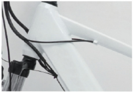
Stem AssemblyStem fitted in the head tube with an expanding bolt (figure 1). Insert the stem into the head tube, respecting the minimum insertion limit as indicated on the stem, and tighten the expanding bolt to 18Nm. Important: Before tightening the stem, make sure that it is in line with the front wheel.
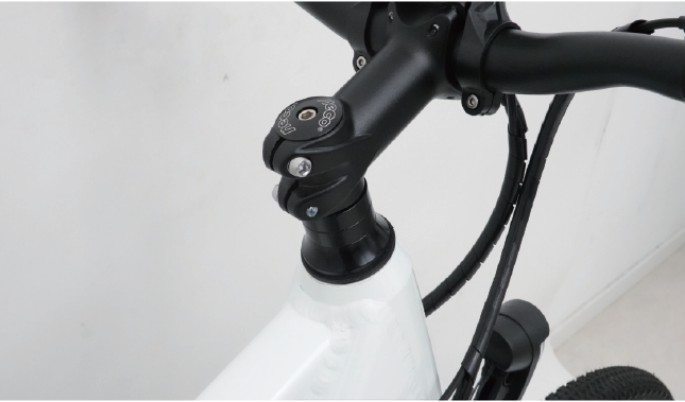
Figure 1
Handlebar AssemblyPosition the handlebar inside the stem (figure 2). Respecting assembly indications on the handlebar, tighten the screw to 18Nm. Before completely tightening, check that the handlebar, the brake levers, and the shifter are correctly positioned.

Figure 2
Brake AdjustmentTo adjust the disk brakes, loosen bolts of the dIsk brake caliper, then activate the brake lever. Keep the brake lever tightened, then tighten the caliper’s bolts. This enables the brake caliper to center. Tighten the brake disks to the wheels and tighten the cable if it is a mechanical brake.
Disk Brake Fine TuningLoosen the screws slightly to adjust the position of the brake caliper until the brake block doesn’t rub against the disk. Slightly adjust the position of the calipers and the position of the brake blocks so that gaps between the blocks and the disk are evenly spaced. Adjust the brake cable so that the distance between the brake shoe and the disk is between 0.5 – 1mmWhen re-tightening the screws ensure they are symmetrical to avoid deformation of the roto and even wear on the brake pads.
Wheel MountingInsert the maximum length of the skewer into the wheel hub, tighten the locknut and tighten the whole system with the quick release lever (figure 3). Make sure that the wheel is correctly fitted. 
Figure 3
Seat AssemblyInsert the seat stem into the frame (figure 4), you can use grease to help assembly. Insert at least to the minimal indication on the seat stem using rotary movements.Pull the quick-release lever free and insert the seat-post to the minimal insertion marker indicated on the seat post. Tighten the quick-release clamp and then fold the lever to the closed position. Minimal torque specifications are 19.5Nm.
Torque SpecificationsThe handlebar is fitted to a stem. The height of some stems can be adjusted. If you must dismantle the handlebar or turn it to transport the bicycle, please make sure that you correctly reassemble and center the handlebars; check the position by placing your hands on the grips to find the best position. Make sure all bolts are correctly tightened. Oncethe handlebar and stem are assembled, make sure that the brake and derailleur sheaths are free.Recommended torque specification: 13-14Nm.Recommended torque specification for the rear rack is 16Nm.You can adjust the angle of the stem by adjusting the bolt located under the stem using an Allen key. Once you have found the desired angle, tighten the stem to the headset.Recommended torque specifications are 18-20Nm.If you remove nut fitted wheels, make sure that when you replace them you respect a minimal recommended torque specification of 30Nm for the rear wheel and 25Nm for thefront wheel.Derailleur AdjustmentsYour bicycle is generally fitted with one derailleur located to the rear, or sometimes a front one and a rear one. They are operated by the gear shifters; the front one on the left of the handlebars, and the rear on the right of the handlebar. There are two types of shifters; the twist style (turn towards you for easier hill ascension or away from you to go downhill), or the push and pull trigger-style shifters (where you push with your thumb to go up in the gears and pull with your index finger to shift down in the gears).To adjust, use the adjustment nob to tighten or loosen the derailleur ur cable. You can also use the two adjustment screws so that the chain does not come off when free-wheeling.
Rear Derailleur Travel:To prevent the cha n from jumping go of the cogs, it is important to adjust the derailleur travel using ‘H’ and ‘L’ stops (figure 5).
- Screw H enables the lower stop to be adjusted (small cogwheel): untightening this screw enables the chain to position itself to the outside of the small cogwheel.
- Screw L enables the lower stop to be adjusted (large cogwheel): untightening this screw enables the chain to position itself to the outside of the large cogwheel.
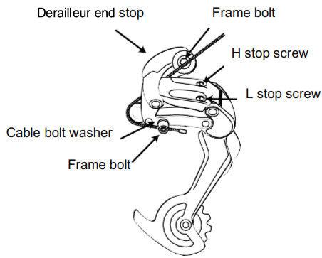
Figure 5
Front Derailleur Movement:
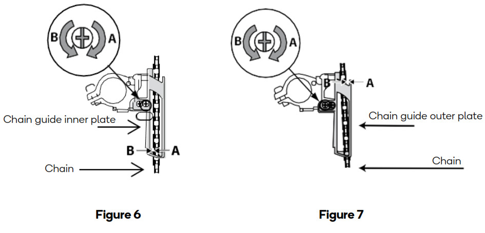
- Adjusting the inner stop (figure 6).By turning the outer screw of the front derailer in direction A, the derailer range moves towards the smallest chainring; by turning it in direction B, it moves away from the large chainring. Then adjust so that the clearance between the chain guide inner plate and the chain is between 0 and 0.5 mm.
- Adjusting the outer stop (figure 7).By turning the inner screw of the front derailer in direction A, the derailer range moves awayfrom the smallest chainring; by turning it in direction B, it moves towards the large chainring. Then adjust so that the clearance between the chain guide outer plate and the chain is 0 to 0.5mm.
Rear Derailleur Travel:Adjusting the cable tension creates a link between a position on the gear lever and a position in the gear system. Unscrew or tighten the cable tension screw at the lever or at the rear of the derailer so that each lever position corresponds to a cog (figure 8):
- If the chain does not move down every time you shift the lever: Loosen the cable by turning the cable tension adjusting screw clockwise.
- If the chain does not move up every time you shift the lever. Tighten the cable up by turning the cable tension adjusting screw anticlockwise.

OPERATION
Presentation and Electrical Start-Up ELECTRONIC PAD LAYOUTUp: More assistanceDown: Less assistanceMode: On/Off Mode
Starting System
- Hold Up button for 3 seconds to turn on the light, hold for another 3 seconds to turn off the light
- Press the Mode button for 2 seconds to start the system.
- Press the Mode button again for 2 seconds to shut the system off.
- If you do not use the bike for 5 minutes, the system automatically shuts down.
LCD Screen Setup and Assistance Level
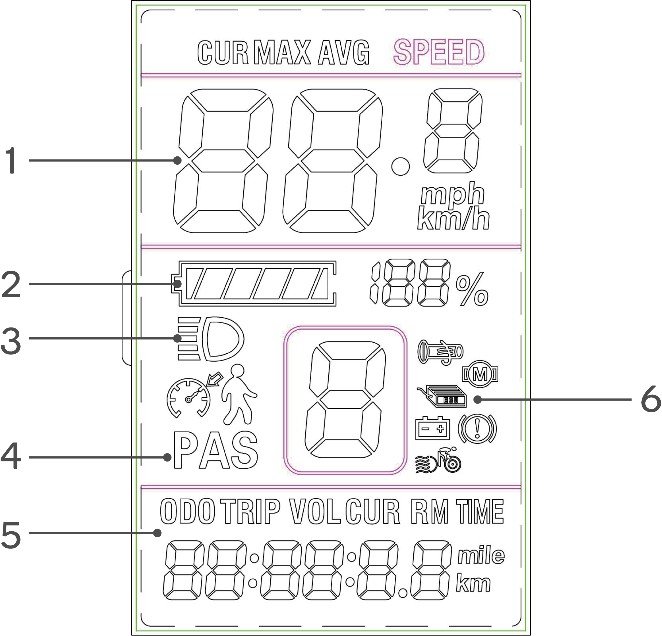
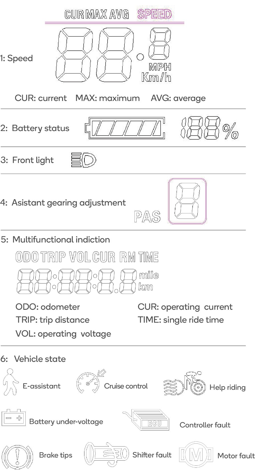
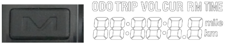
Change Multifunctional indication displayPress briefly on the Mode button to cycle through the different modes:
Battery Management
Battery status
- The battery charge level is displayed by 10 segments which drain thought-out use, the speed of which depending on how (level of assistance) and where you ride (hills,wind…)
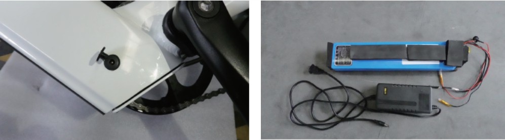
 Battery Mounting and LockingUse the tools supplied in the carton to release the screws and take out the battery. The battery usually will not require removal.
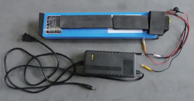
Battery ChargingWith the supplied charger, you can charge the battery directly whilst it is on the bike; the connection plug is located at the bottom of the battery. Make sure that the charge plug is securely in place at all times in order to prevent humidity from entering.
TROUBLESHOOTING
| Error Code | Meaning | Troubleshooting |
| E02 | Brake failure | The brake is in a power-off state. Check whether the left and right brake levers are reset. Check if the fault disappears after opening the junction box and unplugging the power-off switch. Contact Kogan.com for support if the problem persists. |
| E06 | Battery Undervoltage | The battery is low, and the fault code disappears after the battery is fully charged. |
| E07 | Motor failure | The motor is faulty. Check whether the connector of the motor’s waterproof cable is loose. Contact Kogan.com for support if the problem persists. |
| E09 | Controller failure | The controller is damaged and the controller needs to be replaced. After opening the junction box to replace the controller, the fault is eliminated and the fault code disappears. |
| E10 | Communication receiving failure | The communication receiving line between the LCD display and the controller is blocked. Open the junction box, check whether the connectors of the LCD display and the controller are firm. Reconnect the plug and restart. Contact Kogan.com for support if the problem persists. |
| Ell | Communication sending failure | The communication sending line between the LCD display and the controller is blocked. Open the junction box, check whether the connectors of the LCD display and the controller are firm. Reconnect the plug and restart. Contact Kogan.com for support if the problem persists. |
| E12 | BMS communication failure | The communication sending and receiving line between the LCD display and the controller is blocked. Open the junction box, check whether the connectors of the LCD display and the controller are firm. Reconnect the plug and restart. Contact Kogan.com for support if the problem persists. |
| E13 | Headlight failure | The front light of the instrument is damaged or the plug-in is in poor contact. Open the junction box, unplug and reinsert it. Contact Kogan.com for support if the problem persists. |
| E21 | Abnormal current | The vehicle is short-circuited or overloaded. Stop using it immediately and conduct professional inspections |
| E23 | Motor phase loss | The rear wheel motor connector is loose. Check the waterproof connector of the motor and reinsert it firmly. If the fault still exists, the motor coil is damaged, and the fault disappears after replacing the motor. Contact Kogan.com for support. |
| E24 | Motor hall sensor error | The rear wheel motor connector is loose. Check the waterproof connector of the motor and reinsert it firmly. If the fault still exists, the hall sensor in the motor is damaged. Cease use immediately, and contact Kogan.com for support. |
| E25 | Braking error | The brake is in a power-off state. Check whether the left and right brake levers are reset. Check if the fault disappears after opening the junction box and unplugging the power-off switch. Contact Kogan.com for support if the problem persists. |
| E30 | Abnormal communication | The communication sending and receiving line between the LCD display and the controller is blocked. Open the junction box, check whether the connectors of the LCD display and the controller are firm. Reconnect the plug and restart. Contact Kogan.com for support if the problem persists. |
CLEANING & CARE
Care and LubricationOnly use specific bicycle lubricants.Pedals: A few drops every 6 months on the axle.Chain: Spray the whole surface every 6 months.Bottom bracket: Every 6 months, please check with your authorized dealer.Motor: Every year, please check with your authorized dealer.
Maintenance and Advice
- Never modify your bicycle with non-certified parts.
- Never ride in deep water.
- Do not use it for jumps or stunts.
- Avoid long-distance rides when it is raining.
- Keep both hands on the handlebar.
- Avoid sudden braking.
- Be careful when riding in pools of water.
- Thoroughly check the bicycle before each ride.
- Avoid leaving your bicycle in heavy rain or snow. If you do so, wipe dry.
 It is highly recommended to have your bike serviced by an authorized dealer at least once a year or every 1000km. Check your brake cables, sheaths, and brake pads. Lubricate alltransmission components, chain, and derailleur with a suitable product. If the rear tire has a puncture, remember that if you must remove it, it is attached to the motor, so make sure to disconnect the cable (pictured here).When you reach 5000km or 100 charge cycles, a service alert will show for 4 seconds when you start the system, indicating that it is time to plan a service.
NOTES
_________________________Need more information?We hope that this user guide has given you the assistance needed for a simple setup.For the most up-to-date guide for your product,as well as any additional assistance you may require,head online to help.kogan.com

[xyz-ips snippet=”download-snippet”]