Owner’s ManualStereo rack monitorRM-3DT
Thank you very much for purchasing a Fostex product.This manual provides instructions for the basic use of the unit.Read this before using the unit for the first time.
© FOSTEX COMPANY All Rights Reserved.
Introduction
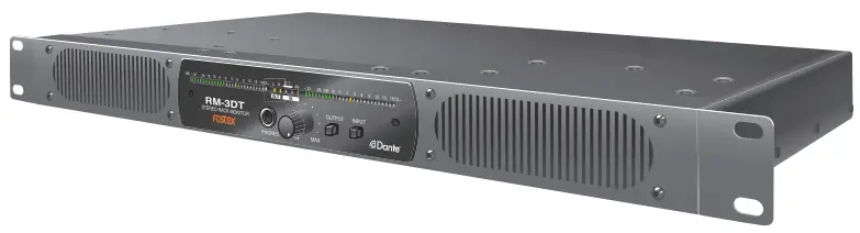
The RM-3DT is a rack-mount type powered monitor equipped with a Dante function and provides Dante network signals and analog audio signals monitoring.
WARNINGS and PRECAUTIONS
- CAUTION: The symbol
 To prevent electric shock hazard, do not connect to mains power supply while the grille is removed.
 - WARNING: An apparatus with CLASS I construction shall be connected to a MAINS socket outlet with a protective earthing connection.
- CAUTION: TO PREVENT ELECTRIC SHOCK, MATCH WIDE BLADE OF PLUG TO WIDE SLOT, FULLY INSERT.
- WARNING: To reduce the risk of fire or electric shock, do not expose this apparatus to rain or moisture.
- CAUTION: Use of any controls or adjustments or performance of procedures other than those herein specified may result in hazardous radiation exposure.
- WARNING: Changes or modifications to this unit not expressly approved by the party responsible for compliance could void the user’s authority to operate the equipment.
- WARNING: Do not place the unit on top of any soft, porous, or sensitive surfaces to avoid damaging the surface. Use a protective barrier between the unit and the surface to protect the surface.
- WARNING: The use of this unit near fluorescent lighting may cause interference regarding the use of the remote. If the unit is displaying erratic behavior move away from any fluorescent lighting, as it may be the cause.
- WARNING: Do not install this equipment in a confined space such as a bookcase or similar unit.
- WARNING: Mains plug is used as a disconnect device and it should remain readily operable during intended use. In order to disconnect the apparatus from the mains completely, the mains plug should be disconnected from the mains socket outlet completely.
![]()
WARNING: TO REDUCE THE RISK OF ELECTRIC SHOCK, DO NOT REMOVE COVER (OR BACK).NO USER-SERVICEABLE PARTS INSIDE. REFER SERVICING TO QUALIFIED SERVICE PERSONNEL.
 The lightning flash with the arrowhead symbol, within an equilateral triangle, is intended to alert the user to the presence of uninsulated “dangerous voltage” within the product’s enclosure that may be of sufficient magnitude to constitute a risk of electric shock to persons.The exclamation point within an equilateral triangle is intended to alert the user to the presence of important operating and maintenance (servicing) instructions in the literature accompanying the appliance.
SAFETY INSTRUCTIONS
- Read Instructions – All the safety and operating instructions should be read before the appliance is operated.
- Retain Instructions – The safety and operating instructions should be retained for future reference.
- Heed Warnings – All warnings on the appliance and in the operating instructions should be adhered to.
- Follow Instructions – All operating and use instructions should be followed.
- Water and Moisture – The appliance should not be used near water – for example, near a bathtub, washbowl, kitchen sink, laundry tub, in a wet basement, or near a swimming pool, and the like.
- Carts and Stands – The appliance should be used only with a cart or stand that is recommended by the manufacturer.The appliance and cart combination should be moved with care. Quick stops, excessive force, and uneven surfaces may cause the appliance and cart combination to overturn.
- Wall or Ceiling Mounting – The appliance should be mounted to a wall or ceiling only as recommended by the manufacturer.
- Ventilation – The appliance should be situated so that its location or position does not obstruct proper ventilation. For example, the appliance should not be situated on a bed, sofa, rug, or similar surface that may block the ventilation openings; or, placed in a built-in installation, such as a bookcase or cabinet that may impede the flow of air through the ventilation openings.
- Heat – The appliance should be situated away from heat sources such as radiators, heat registers, stoves, or other appliances (including amplifiers) that produce heat.
- Power Sources – The appliance should be connected to a power supply only of the type described in the operating instructions or as marked on the appliance.
- Grounding or Polarization – The precautions that should be taken so that the grounding or polarization means of the appliance are not compromised.
- Power Cord Protection – Power-supply cords should be routed so that they are not likely to be walked on or pinched by items placed upon or against them, paying particular attention to cords at plugs, convenience receptacles, and the point where they exit from the appliance.
- Cleaning – The appliance should be cleaned only as recommended by the manufacturer.
- Nonuse Periods – The power cord of the appliance should be unplugged from the outlet when left unused for a long period of time.
- Object and Liquid Entry – Care should be taken so that objects do not fall and liquids are not spilled into the enclosure through openings.
- Damage Requiring Service – The appliance should be serviced by qualified service personnel when:A. The power supply cord or the plug has been damaged; orB. Objects have fallen, or liquid has been spilled into the appliance; orC. The appliance has been exposed to rain; orD. The appliance does not appear to operate normally or exhibits a marked change in performance; orE. The appliance has been dropped, or the enclosure damaged.
- Servicing – The user should not attempt to service the appliance beyond thatdescribed in the operating instructions.All other servicing should be referred to qualified service personnel.
- The appliance should be situated away from drops of water or spraying water.
- Objects containing liquid such as vases must not be put on the appliance.
- The appliance is not completely isolated from the power supply even if the power switch is in the off position.
- The appliance shall not be exposed to dripping or splashing and no objects filled with liquids, such as vases, shall be placed on the appliance.
- Only use attachments/accessories specified by the manufacturer.
- Appliances with a protective earth terminal should be connected to a mains outlet with a protective earth connection.
- The appliance should be placed in a position where an AC plug/inlet can be easily pulled out by hand.
- The main plug is used as the disconnection device. It shall remain readily operable and should not be obstructed during intended use. To completely disconnect the appliance from supply mains, the mains plug of the appliance shall be disconnected from the mains socket outlet completely.

FCC (U.S.A.) & ICES-003 (Canada) INFORMATION
- IMPORTANT NOTICEThis product, when installed as indicated in the instructions contained in this manual, meets FCC and ICES-003 requirements. Changes or modifications not expressly approved by Fostex Company for compliance could void the user’s authority to operate the equipment. DO NOT MODIFY THIS PRODUCT.
- IMPORTANTIn order to comply with FCC and ICES-003 requirements, use high-quality shielded cables for connection to accessories and/or another product. If any cables are supplied with this product, they MUST be used. Follow all installation instructions. Failure to do so could void your FCC / ICES-003 authorization to use this product in the USA / Canada.
- NOTEThis equipment has been tested and found to comply with the limits for a Class B digital device, pursuant to Part 15 of the FCC Rules. These limits are designed to provide reasonable protection against harmful interference in a residential installation. This equipment generates, uses, and can radiate radio frequency energy and, if not installed and used in accordance with instructions, may cause harmful interference to radio communications. However, there is no guarantee that interference will not occur in a particular installation. If this equipment does cause harmful interference to radio or television reception, which can be determined by turning the equipment off and on, the user is encouraged to correct the interference by one or more of the following measures:• Reorient or relocate the receiving antenna.• Increase the separation between the equipment and receiver.• Connect the equipment into an outlet on a circuit different from that to which the receiver is connected.• Consult the dealer or an experienced radio/TV technician for help.
- Compliance with Part 15 of FCC Rules and Canadian ICES-003.This device complies with Part 15 of the FCC Rules. Operation is subject to the following two conditions: (1) This device may not cause harmful interference, and (2) this device must accept any interference received, including interference that may cause undesired operation.This Class B digital apparatus complies with Canadian ICES-003. Cet appareil numérique de la classe B est conforme à la norme NMB-003 du Canada.
Features of the RM-3DT
- The unit supports balanced analog input and Dante input.
- It has a power-saving design with a digital amplifier and a switched-mode power supply.
- The 26 dots LED meter supports 4 different display modes: VU, VU+PEAK, VU+PEAK HOLD, PEAK+PEAK HOLD.
- The display has 4 brightness settings.
- The unit is designed to output either or both of any two-channel digital signals out of Dante network signals.
Dante Network and System
Dante® is a network-audio protocol developed by Audinate.Dante network system transmits multiple uncompressed digital audio signals over IP networks compatible with Gigabit Ethernet.For more information on Dante, visit the website below.www.audinate.com
Accessories
- Power cable (USA: 1 pc, EUR/UK: 2 pcs)
- Rubber feet × 4
- Safety information sheet × 1
- Owner’s manual (this manual) × 1
Part names and functions
Front
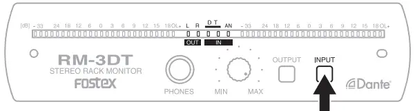
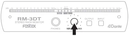
| ① SpeakersThe speakers do not emit any sound while headphones areconnected to the [PHONES] jack.② Level meter③ Status display④ [PHONES] jack⑤ Volume knob | ⑥ Mute buttonPress the button for approximately one second to mut( page 6). Cancel mute by briefly pressing the button again.⑦ [OUTPUT] switchpage 6⑧ [INPUT] switchpage 6 |
Back
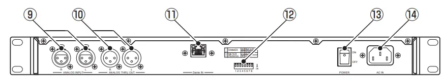
| ⑨ [ANALOG INPUT] terminals (XLR)⑩ [ANALOG THRU OUT] terminals (XLR)Outputs the signal being input through the [ANALOG INPUT](XLR) terminal.⑪ [Dante IN] terminalInputs Dante signals.Connects a LAN cable (RJ45 type). Use an Ethernet cable withCAT5e or higher.⑫ DIP switchesUsed to configure various settings ( page 4). | ⑬ [POWER] switch⑭ [AC IN] terminalUsed to connect to a power outlet using the supplied power cord.A grounding-type plug has a third grounding prong. The third prong is provided for your safety.If the provided plug does not fit into your AC outlet, consult an electrician for the replacement of the obsolete outlet.Do not use any power cord other than the one supplied. |
DIP switch settings
DIP switch(default settings)
Display brightness (DIMMER)
| 1 | 2 | Setting |
| OFF | OFF | Bright |
| ON | OFF | |
| OFF | ON | |
| ON | ON |
![]() Level meter type(METER PEAK/ VU)
Level meter type(METER PEAK/ VU)
| 3 | 4 | Setting |
| OFF | OFF | VU+PEAK |
| ON | OFF | VU+PEAK HOLD |
| OFF | ON | PEAK+PEAK HOLD |
| ON | ON | VU |
![]() Reference level (REF LVL)
Reference level (REF LVL)
Choose an analog reference level indicated by 0 dB on the level meter.Analog input
| 5 | Setting |
| OFF | +4 dBu (balanced) |
| ON | 0 dBu (balanced) |
![]() Source sound type (SOUND)
Source sound type (SOUND)
There are two sound types. Choose the appropriate sound type.
| 6 | Setting |
| OFF | MUSIC |
| ON | VOICE |
MUSIC: Ideal for sound sources that have a wide frequency range, such as music.VOICE: Ideal for sound sources that have a narrow frequency range, such as speech.
![]() Volume when muted ( page 6) (MUTE)
Volume when muted ( page 6) (MUTE)
| 7 | Setting |
| OFF | Volume: –∞ |
| ON | Volume: –20dB |
 Not used.
Meter
Meter scale
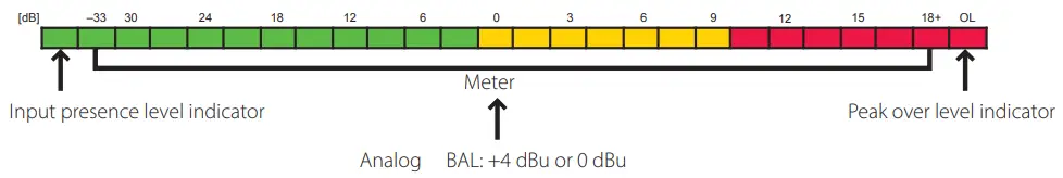
The meter scale has 26 dots LED consisting of a 24 dot level meter, an input presence level indicator, and a peak over the level indicator.You can choose from four combinations of PEAK and VU to be displayed on the meter (“DIP switch settings” ( page 4)).
24 dot LED (VU meter, PEAK meter)
| Scale | Alignment Level | Permitted Level |
| –33 to +18 | @0 dB = standard | @+9 dB |
- Reference levelReference level display position: 0 dBYou can choose the reference level from +4 dBu or 0 dB for analog input using the DIP switches.
Peak meter specifications
| Attack Time | Fall Time | Peak hold time |
| 0.1 msec | 1.7 sec/20 dB | 2.0 sec |
VU meter specifications
| Attack/Fall Time |
| 300 msecAgo0 dB |
Input presence level indicator
| Presence level | Presence hold time |
| @–46 dB | 1.0 sec |
Peak over the level indicator
| Peak over level |
| Reference level +20 dB |
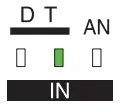
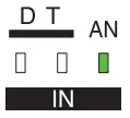
- [INPUT] switchSelect the input (analog or Dante) to monitor.The unit will automatically store the switch status within approximately three seconds.
Indicator Status Analog input Dante input (Synchronized to Dante input signal) Dante input (Synchronized as clock master) Dante input (Desynchronized) <Caution>
(LR alternate yellow lighting/red blinking) This indicates reboot request status.When the Dante module of this unit has been upgraded using the Dante controller, confirm the above indication, and turn the power off and then apply the new firmware.Since rebooting cannot be commanded from the Dante controller, it is necessary to manually turn the power of the unit off and then on to apply the new firmware.
- [OUTPUT] switchSelect the output channel.The unit will automatically store the switch status within approximately three seconds.
- Mute buttonPress the mute button for approximately one second to mute the unit.When in mute, briefly press the mute button again to return to the normal state.The unit is never muted (sound can be heard) when it is turned on.

Dimensions
Specifications
Speakers
| Built-in unit | 110 × 40 mm antimagnetic cone speakers |
| Impedance | 8 Ω |
| Output sound pressure level | 84 dB/W (1 m) |
| Frequency characteristic | 200 Hz to 20 kHz |
Power amplifier
| Maximum output | 10 W × 2 | |
| Residual noise | –50 dB or less (DIN AUDIO) | |
| Distortion rate | 0.1% or less | |
| Dante input
|
Connector | RJ45 |
| Format | Dante | |
| Analog input
|
Connector | XLR-3-31 type |
| Rated input level | XLR (balanced) +4/0 dBV | |
| Input impedance | 10 kΩ or more | |
| Analog THRU output | Connector | XLR-3-32 type |
| Phones | Connector | Φ6.3 mm stereo phones |
| Adapted load impedance | 16 Ω or more | |
| Maximum output | 20 mW+20 mW (32 Ω, 1 kHz) | |
| Level meter | Display | 26 dot LED × 2 |
| Reference level | Analog | XLR: +4/0 dBu |
General
| External dimensions (mm) | 482 (W) × 44 (H) × 284 (D) (includes protruding parts) |
| Unit weight | approx. 3.5 kg |
| Power | AC 100 V to 240 V 50/60 Hz |
| Power consumption | 10 W |
Declaration of EC Directive
This equipment is compatible with the EMC Directive (2014/30/EU) – Directive on the approximation of member nation’s ordinance concerning the electromagnetic compatibility and with the Low Voltage Directive (2014/35/EU) – Directive on the approximation of member nation’s ordinance concerning electric equipment designed to be used within the specified voltage range.The full text of the EU declaration of conformity is available at the following internet address:https://www.fostexinternational.com/docs/tech_support/declaration-conformity.shtml
| The Affect of Immunity on This Equipment |
| The effect of the European Specification EN61000-6-1 (coexistence of electromagnetic waves – common immunity specification) on this equipment is shown below. |
| In the electrical fast transient/burst requirements, surge, conducted disturbances by radio-frequency fields, power frequencymagnetic field, radiate electromagnetic field requirements, and static electricity discharging environment, this could be affected by the generation of noise in some cases. |
FOSTEX DISTRIBUTORS LIST IN EUROPE* Including non-EU countries (as of Nov. 2020)
GermanyNAME: Mega Audio GmbHADD: Feldborn 3, in 55444 Waldlaubersheim, GermanyTEL: (+49) 6707 914 522FAX: (+49) 6721-32046Email: [email protected]Website: http://www.megaaudio.de
UKNAME: SCV DistributionADD: Unit C1 Belcon Industrial Estate, Geddings Road,Hoddesdon, Hertfordshire, EN11 0NT, UKTEL: +44 (0)3301 222500FAX: +44 (0)1992 44 9171Email: [email protected]Website: http://www.scvdistribution.co.uk
Fostex Company, a division of Foster Electric Company, Limited1-1-109, Tsutsujigaoka, Akishima City, Tokyo, 196-8550, JapanTEL: (+81) 42 546 4974
 report this ad
© Printed in China Dec. 2020
References
SCV Distribution | Professional & Consumer Audio Technology
Home – MIP.BZ – Dystrybutor nowoczesnych technologii audio
Your Partner in Pro Audio | XLR
Nordic Pro Audio ApS
Аудиомания: Hi-Fi и High End домашние кинотеатры, электроника, акустика, кабель, стойки…
index
Audinate – Maker of Dante, Pro AV\’s Leading Networking Technology
Rock Centrum – Ten pravý zvuk pre Vás!
Suomen eniten maailman parasta hifiä American Express Apple Pay Klarna Mastercard PayPal Visa
Home
Home – Mafico
DVDPLANET
Συστήματα Ήχου – Εικόνας & Μουσικός Εξοπλισμός | Bon Studio
Art of Music
Player Music Store – Plaćanje Na 12 Rata Bez Kamate!
Equipos de Alta Fidelidad y High-End – AT Consumer
Professionelle Audiotechnik – Mega Audio
Centrum.sk
For the stories you haven\’t yet told
Praha Music Center
Backline – play music at its best – Home
Extreme Audio – Hi-Fi & Home Cinema
Blade
[xyz-ips snippet=”download-snippet”]