FREQUENCY CENTRAL High Towers
High Towers is a 4 channel programmable and addressable clock divider. It is more than the sum of it’s parts.
High Towers internal operations can be considered as 4 clock dividers slaved to an incoming clock. The 4 clock dividers are labelled A, B, C, and D, the divisions for each divider may be selected using the presets and the individual division selectors. The clock dividers can be set to count up, down, or to one of a variety of modes that move between counting up and down.Furthermore, the division of each clock can be set by external CV.For further information see the High Towers User Guide.
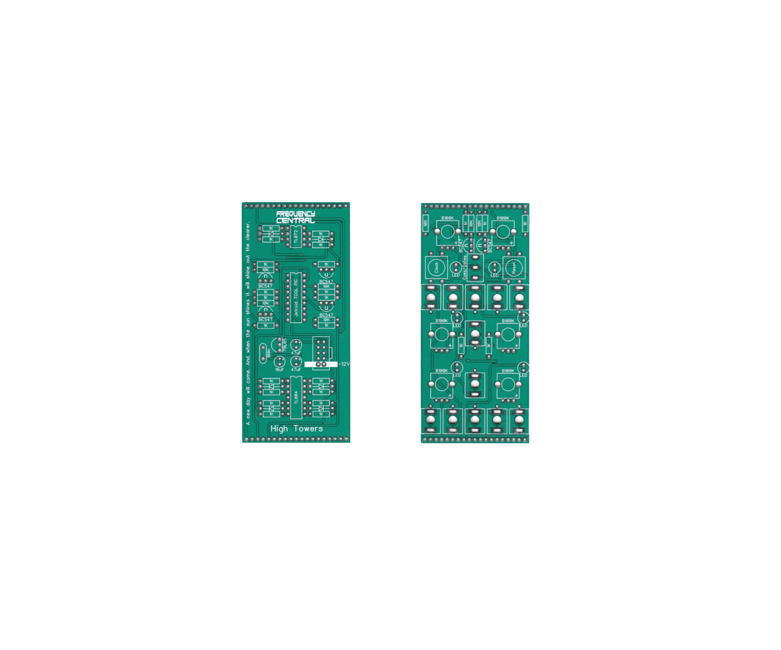
Key to PCB screen print
This signifies NPN BC547 transistors. Note the correct pinout as shown by the half circles.Please observe the correct polarity for all ICs, voltage regulators, diodes and electrolytic capacitors.
Bill of Materials
You will notice that all of the components listed below are also hyperlinks to where I buy each specific part from. You can also use the hyperlinks to find out more about what each component looks like. If you want to know even more, Google is your friend.
| 1K x 2510K x 7
All resistors ¼ watt metal film. |
100nF x 110uF x 147uF x 2 | TOOL PIC
TL084 x 1TL072 x 1BC547 x 61N4148 x 678L05 x 13mm red LED x 614 pin IC socket x 2 8 pin IC socket x 1 |
B100K x 2 metal shaft
B100K x 4(or these)* plastic shaft 3.5mm socket x 12 Tactile switch x 2 Male header x 1(cut to size)Female header x 1(cut to size)Power header x 1 Knobs x 2 |
| * I prefer the Song Huei tall trimmers because they have a longer shaft and a white notch. |
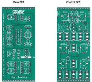
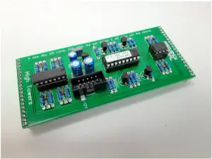
Main PCB assembly
- Solder the diode and all resistors
- Solder all three IC sockets
- Solder the non electrolytic capacitors
- Solder the 78L05 and BC547s watch the polarities!
- Solder the box power header. Make sure the notch lines up with the screen print legend. If in doubt, have a look at a power cable, and make sure when inserted into the header the red stripe lines up with the -12V screen-print.
- Solder all electrolytic capacitors
- Cut male headers to size and solder them into place. Make sure that they stick out of the bottom of the PCB.

Control PCB assembly
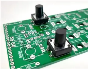
- Place the PCB on a flat surface. Place the 2 tactile switches into their solder pad. Do not push them all the way through, they should sit proud of the PCB (see photo), their legs should not protrude through the other side. Solder them into place from the top of the PCB.
- Solder the 8 resistors.
- Solder the 2 x BC547.
- Solder the 2 x metal shaft pots.
- Solder the 12 x sockets. Use the panel to ensure these line up nicely. You can use cut off resistor legs to make the ground connections.
- Cut female headers to size and solder them into place. Make sure that they stick out of the bottom of the PCB.
- Solder the 4 x plastic shaft pots
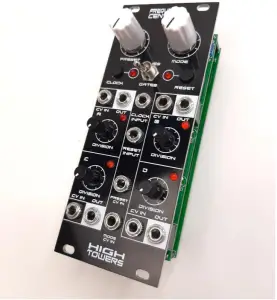
- Solder the 6 x LEDs. Use the panel to ensure that these line up nicelyBolt the metal shaft pots and the sockets to the panel using their nuts and washers. Pop the knobs on the pots and the caps on the sliders. Looks nice huh?
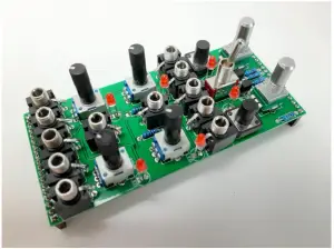 Bolt the metal shaft pots and the sockets to the panel using their nuts and washers. Pop the knobs on the pots and the caps on the sliders. Looks nice huh?
Calibration
- There is nothing to calibrate on this module cool!
- Go forth and divide.
Troubleshooting
Not all DIY builds work first time. The vast majority of build issues are down to soldering inconsistencies. This is far more likely than a bad IC, for example. The first step of successful troubleshooting should always be to reflow all soldering to eliminate any dry joints (bad connections) or solder bridges (short circuits). This is also an opportunity to closely inspect your work you might find some unsoldered pads, or an IC not inserted into its socket, for example. Next steps are to double check all resistor values are correct, and to check polarities of all diodes, transistors, ICs and electrolytic capacitors. This is not an exhaustive troubleshooting guide, but should address 95% of build issues.
http://www.frequencycentral.co.uk/
References
47uF 25V 105C Aluminum Electrolytic Capacitor 5x11mm PANASONIC
100K OHM Linear Taper Potentiometer Round Knurled Plastic Shaft PCB 9mm
40 Pin 2.54 mm Single Row Pin Header Strip
Google
TL072 LOW NOISE J-FET DUAL OP-AMP IC
BC547 Transistor NPN 45V 0.1A
10uF 25V 105C Radial Electrolytic Capacitor 5x11mm
100K OHM Linear Taper Potentiometer Round Shaft PCB 9mm
Tact Switch 12*12mm 12mm Through Hole SPST-NO
Flower Pot Men – Wikipedia
3.5mm Enclosed Socket
8 pin DIP IC Socket Adaptor Solder Type
Save time Easy Ordering Page for 1/4W 1% Resistors
L78L05ACZ L78L05 78L05 +5 VOLTS 100mA Voltage Regulator IC
100nF 0.1uF 100V 5% Polyester Film Box Type Capacitor
Tall Trimmer 9mm Pots – Thonk – DIY Synthesizer Kits & Components
Knob DAVIES 1900H CLONE White
14 pin DIP IC Socket Adaptor Solder Type
LED 3mm Red
10 Pin Box Header Connector 2.54mm
Frequency Central
1N4148 Switching Signal Diode
40 Pin 2.54 mm Single Row Female Pin Header
TL084 Quad Operational Amplifier J-FET PDIP-14 TL084CN
[xyz-ips snippet=”download-snippet”]