![]()
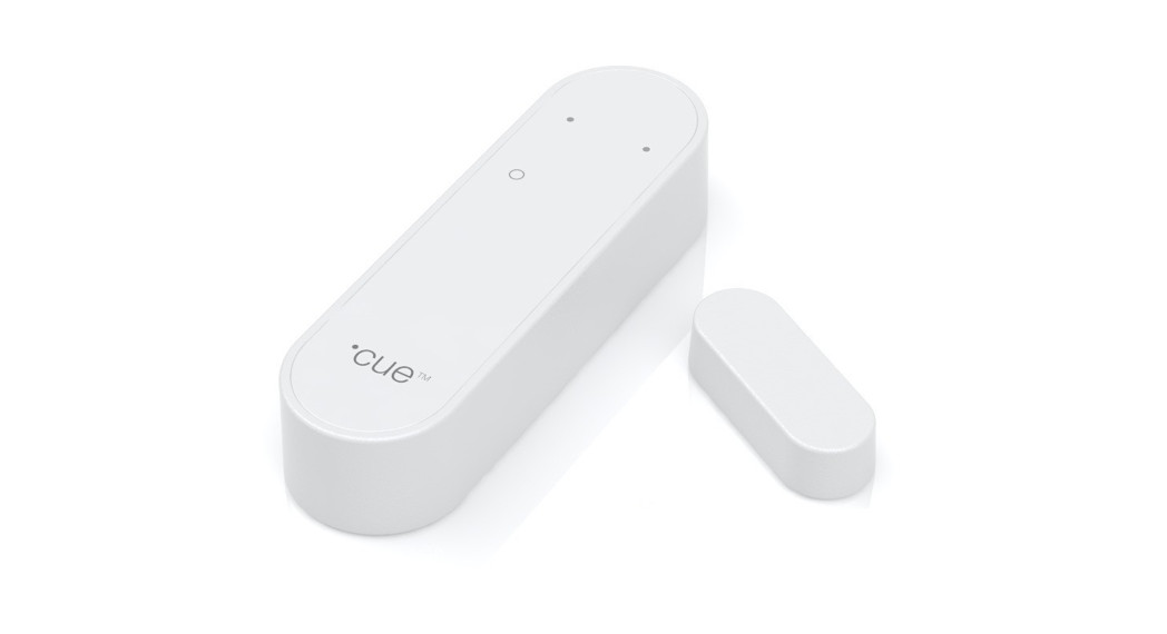
Entry Sensor/Pro
INSTALLATION MANUAL Version 1.3

Product description
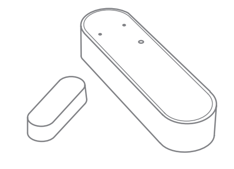
The entry sensor detects and reports the opening and closing of doors and windows. Easily installed on any door or window, the sensor triggers a signal when parted. This lets you know when a room is entered if a window or a door has been left open, etc.
Precautions
- When removing cover for battery change – electrostatic discharge can harm electronic components inside.
- Always mount indoors as the sensor is not waterproof.
- Do not place the sensor close to magnetic or electromagnetic fields. This device includes a magnet. The magnet creates a magnetic field that may cause damage to computer hard drives, magnetic cards, data storage devices, hearing aids, and speakers e.g. Therefore, we strongly advise you to never position the magnet close to electronic devices.
Getting started
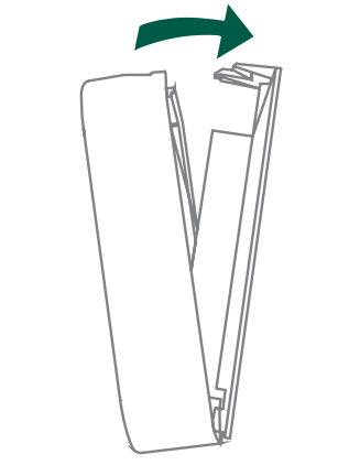
- Open the casing of the device by pushing the fastening on top of the device to remove the front panel from the back cover.

- Insert the enclosed batteries into the device, respecting the polarities
- Close the casing
- The entry sensor will now start searching (up to 15 minutes) for a Zigbee network to join.
- Make sure that the Zigbee network is open for joining devices and will accept the entry sensor.
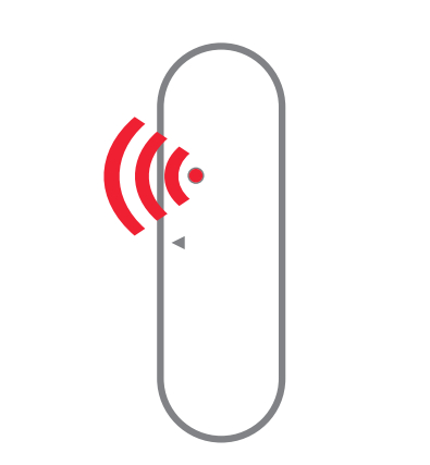
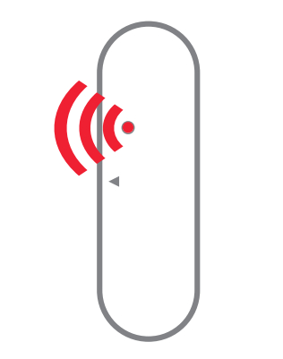
- While the entry sensor is searching for a Zigbee network to join, the red LED is flashing.
- When the red LED stops flashing, the entry sensor has successfully joined the Zigbee network.
Placement
- Place the sensor indoors at a temperature between 0-50°C.
- The magnet has to be placed on that side of the sensor which is marked with a small triangle.
- The magnet and sensor also have to be aligned/centered thickness-wise on as similar a level as possible.
- In case of a weak or a bad signal, change the location of the entry sensor or strengthen the signal with a smart plug.
Mounting
- Clean the surface before mounting.
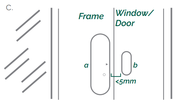
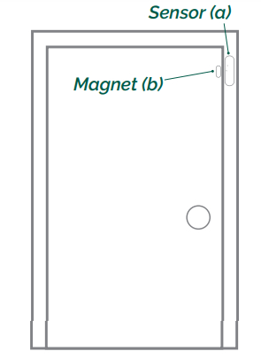
- The entry sensor (a) should be mounted to the frame using the double-stick tape, already applied on the back of the sensor and magnet. Press firmly to secure the sensor.
- The magnet (b) should be mounted on the door or window no further than 5mm away from the arrow on the sensor.
- There are many ways to mount the sensor and magnet, as windows and doors vary greatly. The most important consideration is for the magnet to be placed as near to the point on the sensor indicated by the grey arrow.
- The sensor and magnet may be placed on separate three-dimensional planes, though this does affect the maximum distance allowed. The magnet may also be placed either facing the side of the sensor or sitting parallel to it.
Testing
You can test if the positioning of the sensor and magnet are correct by checking whether the green light on the entry sensor is flashing when you open or close the window/door.
Resetting
Resetting is needed if you want to connect your entry sensor to another gateway or if you need to perform a factory reset to eliminate abnormal behavior. The reset button is marked with a small ring on the front of the sensor.
STEPS FOR RESETTING
- Press and hold down the reset button for approximately 8-10 seconds.
- While you are holding the button down, the LED first flashes once, then two times in a row, and finally numerous times in a row.
- Release the button while the LED is flashing numerous times in a row.
- After you release the button, the LED shows one long flash, and the reset is completed.
Modes
ACTIVATION MODEA single green flash means that the sensor and the magnet are moving either away from or towards each other.

SEARCHING GATEWAY MODERed flashes every second for a longer period means that the device is searching for a gateway.LOST CONNECTION MODEWhen the red LED flashes 3 times, it means that the device has failed to connect to a gateway.LOW-BATTERY MODETwo consecutive red LED flashes every 60 seconds, means that the battery should be replaced.
Fault finding
- If the entry sensor does not work when the window or door is parted, the probable cause is a faulty battery. Replace the batteries if they are worn out.
- In case of a bad or weak signal, change the location of the entry sensor. Otherwise, you can relocate your gateway or strengthen the signal with a smart plug.
- If the search for a gateway has timed out, a short press on the button will restart it.
Battery replacement
CAUTION: RISK OF EXPLOSION IF BATTERIES ARE REPLACED BY AN INCORRECT TYPE. DISPOSE OF THE BATTERIES IN ACCORDANCE WITH INSTRUCTIONS.CAUTION: When removing cover for battery change – Electrostatic Discharge (ESD) can harm electronic components inside
- Open the casing of the device by pushing the fastening on top of the device to remove the front panel from the back cover.
- Replace the batteries respecting the polarities. The entry sensor uses 2xAAA batteries.
- Close the casing.
- Test the entry sensor.
Other information
Note local regulations about information to your insurance company regarding installed entry sensors.
Disposal
Dispose of the product and battery properly at the end of life. This is electronic waste that should be recycled.
Placement Examples – Top View
- The most beneficial distance between the sensor and the magnet is 0.2-0.5 cm. Be aware that on a magnetic surface (e.g. metal door), the distance between the sensor and the magnet has to be 0.1-0.3 cm.
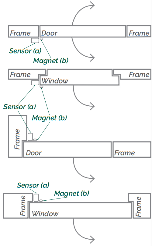
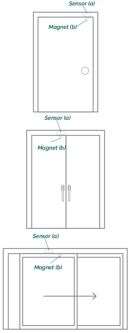
Placement Examples – Doors
- Be sure to mount the sensor on the frame, to protect the electronics from heavy vibrations.
- The sensor and magnet should be mounted on the side opposite from the hinge/pivot point.
- Pay careful attention to the arrow printed on the sensor. This should be oriented to face the magnet. The distance between the two should not exceed 5mm.
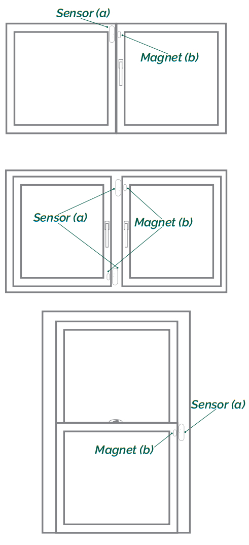
Placement Examples – Window
 Placement Examples – Window
- Be sure to mount the sensor on the frame, to protect the electronics from heavy vibrations.
- The sensor and magnet should be mounted on the side opposite from the hinge/pivot point.
- Alternatively, if the window slides open, the sensor and magnet may be mounted in many positions, however, the sensor should always be placed on the frame.
- Pay careful attention to the arrow printed on the sensor. This should be oriented to face the magnet. The distance between the two should not exceed 5mm.
FCC statement
Changes or modifications to the equipment not expressly approved by the party responsible compliance could void the user’s authority to operate the equipment.
NOTE: This equipment has been tested and found to comply with the limits for a Class B digital device, pursuant to Part 15 of the FCC Rules. These limits are designed to provide reasonable protection against harmful interference in a residential installation. This equipment generates, uses, and can radiate radio frequency energy and, if not installed and used in accordance with the instructions, may cause harmful interference to radio communications. However, there is no guarantee that interference will not occur in a particular installation.If this equipment does cause harmful interference to radio or television reception, which can be determined by turning the equipment off and on, the user is encouraged to try to correct the interference by one or more of the following measures:
- Reorient or relocate the receiving antenna.
- Increase the separation between the equipment and receiver.
- Connect the equipment into an outlet on a circuit different from that to which the receiver is connected.
- Consult the dealer or an experienced radio/ TV technician for help.
This device complies with FCC RF radiation exposure limits set forth for an uncontrolled environment. The antenna used for this transmitter must be installed to provide a separation distance of at least 20 cm from all persons and must not be co-located or operating in conjunction with any other antenna or transmitter. This device complies with part 15 of the FCC Rules. Operation is subject to the following two conditions:
- This device may not cause harmful interference, and this device must accept any interference received, including interference that may cause undesired operation.
IC statement
EnglishThis device contains license-exempt transmitter(s)/receiver(s) that comply with Innovation, Science, and Economic Development Canada’s license-exempt RSS(s). Operation is subject to the following two conditions:
- This device may not cause interference.
- This device must accept any interference, including interference that may cause undesired operation of the device. This equipment complies with IC RSS-102 radiation exposure limits set forth for an uncontrolled environment. This equipment should be installed and operated with a minimum distance of 20 cm between the radiator and your body.
ISED statement
Innovation, Science and Economic Development Canada ICES-003 Compliance Label: CAN ICES-3 (B)/NMB-3(B).
CE certification
The CE mark affixed to this product confirms its compliance with the European Directives which apply to the product and, in particular, its compliance with the harmonized standards and specifications.

- Zigbee Home Automation 1.2 certified.
All rights reserved.friend assumes no responsibility for any errors, which may appear in this manual. Furthermore, the friend reserves the right to alter the hardware, software, and/or specifications detailed herein at any time without notice, and friend does not make any commitment to update the information contained herein. All the trademarks listed herein are owned by their respective owners.Distributed by frient A/S Tangen 6 8200 Aarhus N Denmark www.frient.com Copyright © frient A/S
References
[xyz-ips snippet=”download-snippet”]