FrSky Archer GR8 Receiver Instruction Manual
Introduction
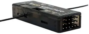
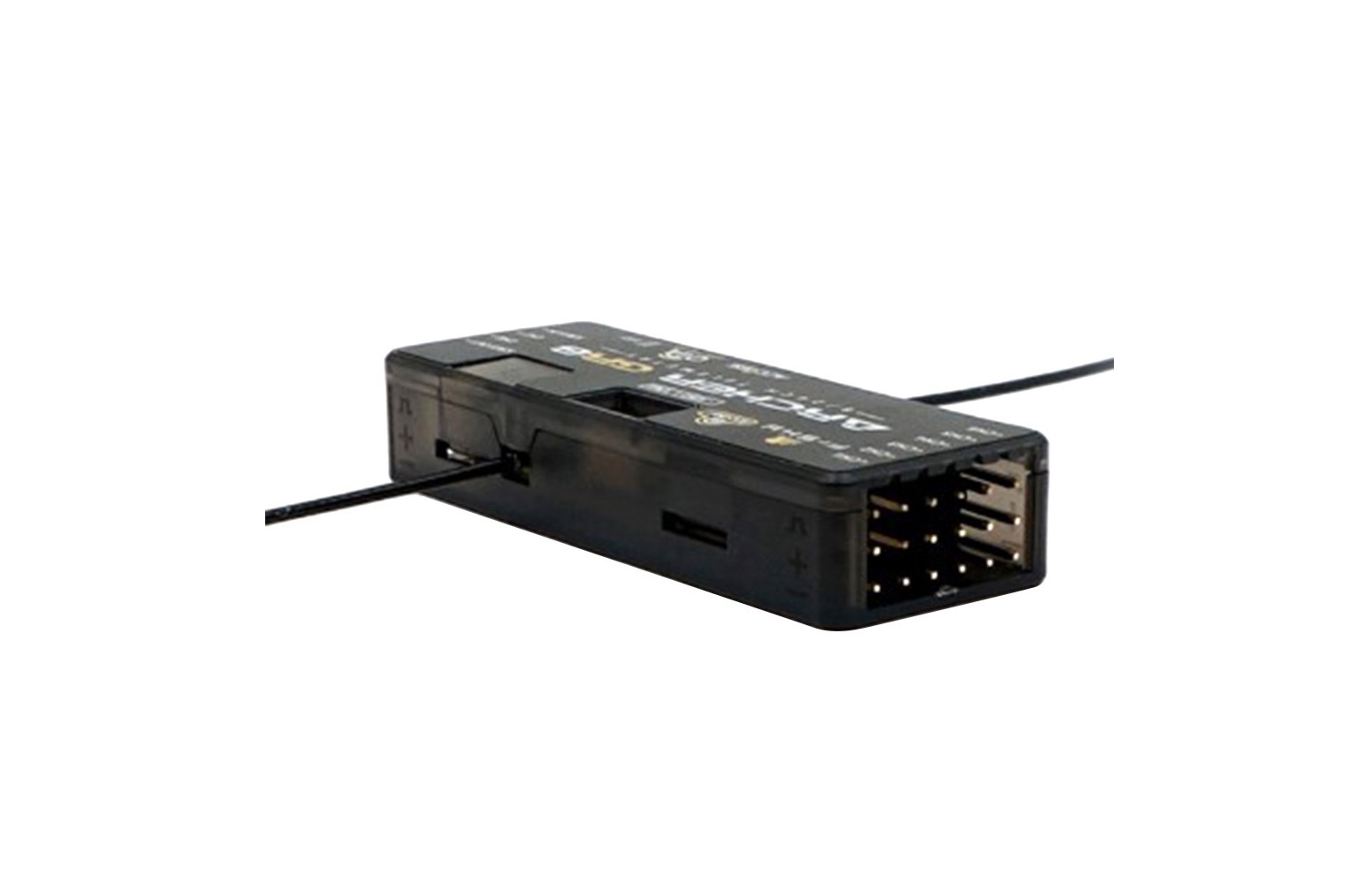
The ARCHER GR8 receiver features the new ACCESS protocol. ACCESS provides the lower latency and increased performance of our previous G-RX8 receivers. With OTA (Over-The-Air) function support firmware upgrades will be very easy, no more wires. The ARCHER GR8 also has an upgraded high precision variometer that gives pilots more accurate and quicker altitude and vertical speed data. Now you can enjoy more accurate and quicker vario audio feedback from your FrSky ACCESS enabled transmitter.
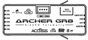
The ARCHER GR8 maintains its small form factor. Thanks to the ACCESS protocol and hardware optimizations, you can now use 8 high-precision PWM channels and 16 SBUS channels via standard servo connectors at the same time. In addition, any SBUS equipped ACCESS receiver can be connected to the SBUS IN port turning it into a redundant receiver, the GR8 will automatically use the receiver with the best signal. Simple battery voltage monitoring is now available through the AIN port.
Overview

Specifications
- Dimension: 54*20*10mm (L*W*H)
- Weight: 9.8g
- Number of Channels: 8/24 channels
- 8 High-precision PWM & 16 SBUS channels
- 8 High-precision PWM & 24 configurable SBUS channels (Stay tuned)
- Operating Voltage Range: 3.5 -10V
- Operating Current: <
- Operating Range: >2km (Full range) (*Range may vary based on local conditions.)
- Variometer Measurement Range
- Altimeter Range & Resolution: -700m to 10000m & 0.1m
- Vertical Speed Range: ±10m/s
- Voltage Measurement Range via AIN2 (External device): 0-3.3V
- Compatibility: All FrSky ACCESS transmitters
Optional Accessories:
IPEX4 dipole copper antenna for 2.4GHz receivers
- Size: 150mm Weight: 1.2g
- Link: https://www.frsky-rc.com/product/archer-gr8/
Features


- ACCESS protocol with Over The Air (OTA)
- Upgraded variometer sensor
- Receiver redundancy
- 8 high-precision PWM channels
- SBUS IN & OUT (using standard servo connectors)
- S.Port / F.Port and AIN2 (on 4 pin socket)
- VFR (Valid Frame Rate) telemetry
LED state
| Green LED | Red LED | Status |
| On | On | Register |
| Flash | Flash | Register successfully |
| On | On | Bind |
| On | Off | Bind successfully |
| On | Off | Working normally |
| Off | On | Failsafe |
Registration & Automatic binding (Smart Match )
Follow the step below to finish the Registration & binding procedure:
- Put the transmitter/transmitter module into [Reg] status.
- For Taranis X-Lite Pro as an example, turn on the transmitter, go to the MENU-MODEL SETUP-PAGE 2, choose Internal or External RF, and select [Reg].
- Connect the battery to the receiver while holding the button on the receiver. The RED LED and GREEN LED on the receiver will be on, indicating into the [Reg] status. Select [ENTER] on the transmitter, The RED LED and GREEN LED on the receiver will flash, and the transmitter displays [Registration ok].
- Turn off the receiver.
- Move the cursor to select the receiver 1 [Bind].
- Connect the battery to the receiver, the GREEN LED will flash, indicating into the [Bind] status. Select the RX, the GREEN will keep lit, and the transmitter displays [Bind successful].
- The transmitter exit [Bind], GREEN LED will keep lit, RED LED will be off, indicating Working normally.
Note: Once the receiver is registered, the button is not needed anymore in the binding process.
How to Switch FS (20ms) mode/HS (7ms) mode
- a) The factory default setting is FS mode.
- b) To go to the receiver [Options], select the 7ms PWM or not
Note: The SBUS output is 7ms, no matter HS/FS mode.
Warning: HS mode is only applied for digital servos. Other servos should select FS mode, otherwise servos will get hot and may burn out.
Warning: [Options ] setting in flight will cause the failsafe.
About OTA function
For Taranis X-Lite Pro as an example, go to the SD CARD 2/7, and select the FW, press the enter button, select [Flash receiver OTA], power on the receiver, select the RX, go to the [ENTER], complete the flash process, the transmitter will display [Flash successful]. Re-power the receiver and wait for 3 seconds, the Green LED starts flashing indicates the receiver works properly at the moment.
Note: Please do not do the binding operation in the near range while the firmware upgrading in progress.
Note: Update the firmware after the receiver gets bound.
Range Check
A pre-flight range check should be done before each flying session. Reflections from nearby metal fences, concrete buildings or trees can cause loss of signal both during range check and during the flight. Under Range Check Mode, the RF power would be decreased and Range distance to 1/30 –1/10 that of Normal Mode.
The signal is completely lost is recommended as the node to complete the range test.
- Place the model at least 60cm (two feet) above non-metal contaminated ground (e.g. on a wooden bench). The receiver antenna should be in vertical position.
- For Taranis X-Lite Pro as an example, turn on the transmitter and power on the receiver, go to: SETUP 2/13 /Internal RF/ Module [Rng].
- For transmitter RF module, please refer to its manual.
Much more operation and instruction please refer to radio manual.
Failsafe
Failsafe is a useful feature which is for a preset channel output position whenever control signal is lost for a period.
Follow the steps to set Failsafe for channels necessary:
Failsafe for receiver supporting ACCESS can be set via radio interface, which support no pulse, hold and custom three modes for each channel.
- For Taranis X-Lite Pro as an example, turn on the transmitter, go to: MODEL SETUP/Internal RF/Failsafe.
- Failsafe can be set on receiver via short pressing F/S button while moving a certain channel position to a preset value after binding.
FCC STATEMENT
- This device complies with Part 15 of the FCC Rules. Operation is subject to the following two conditions:
- This device may not cause harmful interference.
- This device must accept any interference received, including interference that may cause undesired operation.
- Changes or modifications not expressly approved by the party responsible for compliance could void the user’s authority to operate the equipment.
NOTE: This equipment has been tested and found to comply with the limits for a Class B digital device, pursuant to Part 15 of the FCC Rules. These limits are designed to provide reasonable protection against harmful interference in a residential installation. This equipment generates uses and can radiate radio frequency energy and, if not installed and used in accordance with the instructions, may cause harmful interference to radio communications. However, there is no guarantee that interference will not occur in a particular installation. If this equipment does cause harmful interference to radio or television reception, which can be determined by turning the equipment off and on, the user is encouraged to try to correct the interference by one or more of the following measures:
- Reorient or relocate the receiving antenna.
- Increase the separation between the equipment and receiver.
- Connect the equipment into an outlet on a circuit different from that to which the receiver is connected.
- Consult the dealer or an experienced radio/TV technician for help
FrSky is continuously adding features and improvements to our products. To get the most from your product, please check the download section of the FrSky website www.frsky-rc.com for the latest update firmware and manuals
FrSky Electronic Co., Ltd.www.frsky-rc.comContact us : [email protected]
Add: F-4,Building C, Zhongxiu Technology Park, No.3 Yuanxi Road, Wuxi, 214125, Jiangsu, China
Technical Support: [email protected]
References
[xyz-ips snippet=”download-snippet”]


