
ARCHER SR6 Receiver for RC Drone
VersionInstruction Manual for FrSky ARCHER SR6 Receiver
Introduction
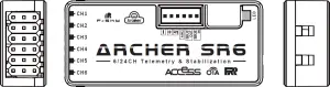
The Archer SR6 are gyro-stabilized receivers with a built-in 3-axis gyroscope and 3-axis accelerometer, they have 6 high-precision PWM channel outputs and features multiple flight modes and configuration methods. They support full-range signal strength with dual detachable antennas it guarantees optimal antenna-reception and maximum range. In addition to all this, the SR6 can also be used as a redundancy receiver along with any other FrSky ACCESS capable receiver equipped with an SBUS port.
All of the Archer receivers are hyper-matched with the ACCESS protocol. They not only feature wireless firmware upgrades and increased range and telemetry performance, the SR6 now supports more functions like configurable telemetry power, S.Port/F.Port switching and FLR output. Additional valuable features are under development to unlock the true potential of the ACCESS protocol.
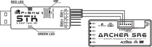
Overview
Working State
| Green LED | Red LED | Status |
| On | On | Register |
| Flash | Flash |
Register successfully
|
| On | Off | Bind |
| Flash | Off | Work Normally |
| Off | On | Failsafe |
| Yellow LED |
State (Calibration of Accelerometer)
|
| ON |
exceeding limits [0.9G, 1.1G]
|
| OFF |
within limits [0.9G, 1.1G]
|
| Flashing | completing |
| Blue LED |
State (Self-check)
|
| ON | in process |
| OFF | completing |
Specifications
- Dimension: 47.5*20.5*11mm (L*W*H)
- Weight: 13g
- 16 / 24 Configurable SBUS Channels
- 6 High-precision PWM Channels
- Operating Voltage Range: 3.5 -10V
- Operating Current:
- Control Range: Full range* with telemetry (*Full Range: 2km, range may vary based on local conditions.)
- Voltage Measurement Range via AIN2 (External device): 0-3.3V
- Compatibility: All FrSky ACCESS transmitters
Features
- ACCESS protocol with Over The Air (OTA)
- Supports signal redundancy (SBUS In)
- Built-in 3-axis gyroscope and 3-axis accelerometer sensor
- Different from ACCST SXR receivers, the SBUS IN signal
- Multiple flight modes and configuration methods (LUA & Freelink) can be adjusted through the STAB module of SR6 when
- Full control range with telemetry the STAB function is enabled.
- S.Port / F.Port / F.Port 2.0
- External battery / device voltage detection
Channels
Number of ChannelCH1 CH2 CH3 CH4 CH5 CH6
Corresponding parts on the model AIL 1 ELE 1 THR RUD AIL 2 ELE 2
Full nameAileron Elevator Throttle Rudder Aileron Elevator
Number of ChannelCH7 CH8 CH9 CH10&CH11 CH12
Corresponding parts on the model User-defined User-defined No mark No mark
Full nameGyro gain adjustment Flight modesSelf-check activation switch
Gyro gain adjustment of CH9: When the the value of CH9 is in the center, the gain is zero. The gain increases as the value gets bigger. Until the value is ±100%, the gain reaches maximum.
FrSky Electronic Co., Ltd.www.frsky-rc.comContact us:
Add: F-4,Building C, Zhongxiu Technology Park, No.3 Yuanxi Road, Wuxi, 214125, Jiangsu, China Technical Support:
01140171
Instruction Manual for FrSky ARCHER SR6 Receiver
Conventional model
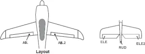
The available flight modes can be assigned to CH10 and CH11 with three-position switches.
| Flight mode | Stabilization | Automatic level | Hover | Knife-Edge | Off |
| CH10 (3 pos SW) | M+H\r\n(CH10 SW Down)”}\’>CH10>M+H(CH10 SW Down) | M+H\r\n(CH10 SW Down)”}\’>CH10>M+H(CH10 SW Down) | M+H\r\n(CH10 SW Down)”}\’>CH10>M+H(CH10 SW Down) | CH10<M-H(CH10 SW Up) |
CH10 SW-mid
|
| CH11(3 pos SW) | M-H<CH11<M+H(CH11 SW Mid) | M+H\r\n(CH11 SW Down)”}\’>CH11>M+H(CH11 SW Down) | CH11<M-H(CH11 SW Up) | M-H<CH11<M+H(CH11 SW Mid) |
Delta wing & Flying wing & V-tail
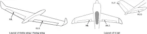
The available flight modes can be assigned to CH10 with a three-position switch.
| Flight mode | Stabilization | Auto Level | Off |
| CH10 | M+H\r\n(CH10 SW Down)”}\’>CH10>M+H(CH10 SW Down) | CH10<M-H(CH10 SW Up) | CH10 SW-mid |
When Delta wing/Flying wing/V-tail is selected, the signal produced by the transmitter should be without active mixes on the channelsrelated to AIL and ELE. SR6 will mix the AIL(CH1) and ELE(CH2) input signal with a fixed mix percentage automatically. Signals onCH4~CH8 will behave as required by the user.M: represents a neutral signal period (1500μs)H: represents the time of required signal change to activate the mode (50μs). When the factory settings are selected, the switch positionshown above represents the required modes.Off: When the mode is activated, SR6 will transmit the received commands produced by the transmitter to the model without compensating.Stabilization: When the model is activated, SR6 will compensate with external forces (wind) as soon as receiving commands from thetransmitter. This function is used to enhance the stability of the model on three axes (Pitch, Roll, Roll). CH9 could be used to adjustgyro gain by assigning a knob or a slider, changing the sensitivity of the counteracting signal produced by the internal three-asisgyroscope.Automatic level: When the mode is activated, SR6 will make the model return to level orientation with internal three-axis accelerometerand three-axis gyroscope on AIL and ELE channels after the sticks being released to neutral. RUD channel works in stabilizationmode only.Flight mode:FrSky Electronic Co., Ltd. www.frsky-rc.com Contact us: Add: F-4,Building C, Zhongxiu Technology Park, No.3 Yuanxi Road, Wuxi, 214125, Jiangsu, China Technical Support:
Note: CH9~CH12 are not marked on the diagram.CH9 Edit — Setting CH9 at Weight 50 and offsetting 50, the assigned pot/slider will work normally.
AttentionsCH1~CH8 should be connected to the corresponding servos.S.Port could be used to update, edit parameter settings via FrSky STK PC tool and connect with telemetry sensors.
Registration & Automatic binding (Smart Match T M )
Follow the step below to finish the Registration & binding procedure:1. Put the transmitter/transmitter module into [Reg] status.1.1 For Taranis X-Lite Pro as an example, turn on the transmitter, go to the MENU-MODEL SETUP-PAGE 2,choose Internal or ExternalRF, and select [Reg].2. Connect the battery to the receiver while holding the button on the receiver. The RED LED and GREEN LED on the receiver will beon, indicating into the [Reg] status. Select [ENTER] on the transmitter, The RED LED and GREEN LED on the receiver will flash, andthe transmitter displays [Registration ok].3. Turn off the receiver.4. Move the cursor to select the receiver 1 [Bind].5. Connect the battery to the receiver, the GREEN LED will flash, indicating into the [Bind] status. Select the RX, the GREEN will keeplit, and the transmitter displays [Bind successful].6. The transmitter exit [Bind], GREEN LED will keep lit, RED LED will be off, indicating Working normally.
Note: Once the receiver is registered, the button is not needed anymore in the binding process.
Set up your model and receiver
You need complete calibration of Accelerometer about the six positions via the STAB RX.Lua/FreeLink APP/FreeLink.exe firstly.Step1: Connect your servos follow the channel list according to your model.Step2: Set you radio follow the channel list.Step3: Choose the Wing Type via the configuration tool (STAB RX.Lua/FreeLink APP/FreeLink.exe).Step4: Choose the AUTO LEVEL mode, check the model servo feedback.Step5: Choose the manual mode, check servo feedback via transmitter.
Quick Mode
It supports stabilization mode and manual (six-axis off) mode and configured through CH10. What’s more, an urgent mode is added to configure automatic level mode default through CH12. The precise configuration is written below.
| Channel | Position | Flight Mode |
|
CH10
|
SW Down | None |
| SW Mid |
Stabilization Mode
|
|
| SW Up |
Automatical Level Mo
|
|
| CH12 | SW Down |
Urgent Mode (Automatic Level Mode)
|
Note: The default mode of SR6 is Quick Mode. When re-flashing firmware of SR6 or replacing with a new one, the presetmode will be cleared out.– If Quick mode is applied, there is no Knife Edge or (3D) Hover mode.– CH11 is not used when using Quick Mode.
Modes
|
Conventional Mode
|
Stabilization |
| Automatic level | |
| Hover | |
| Knife-edge |
| Delta Wing |
stabilizationautomatic level
|
| Flying Wing | |
| V-tail |
Hover: When the mode is activated, SR6 will make the nose of the model straight up with internal three-axis accelerometer andthree-axis gyroscope on RUD and ELE channels (ELE and RUD inputs are not required). Under this mode, AIL is used to control therotation of the model and THR adjust the altitude. AIL channel works in stabilization mode only.Knife-egde mode: When the mode is activated, SR6 will roll the plane on a certain side (wing points up) with internal three-axisaccelerometer and three-axis gyroscope on RUD and AIL channels.Thus, AIL inputs are not required. While the mode steering is donewith ELE, altitude will be maintained with THR/RUD. ELE channel operates in stabilization mode only.
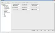
Configuration
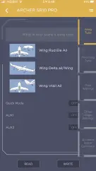
Methods: APP configurationFrSky radio configurationPC configuration software (FrSky STK usb updater)Configuration parameters: Wing type, mounting type, gain setting, offset angle setting, accelerometer calibration.APP(IOS/Android) configuration• Connect the SR6 to the App with AirLink S.The menu screen is displayed below (For SR10 PRO as an example):


FrSky radio configuration:
- Copy the STAB RX.Lua&STAB RX Cali.Lua files to the SCRIPTS/TOOLS on the SD card of the transmitter.
- Run the files.
PC configuration software:
• Connect SR6 as shown below to the FrSky STK usb adapter, and plug it into PC.• Run the Freelink.exe and access the home page.• Press open to connect with SR6.
1. Open: Gives the PC software access to SR8 PRO configuration data.2. Read: Retrieves the stored SR8 PRO data to be edited in the PC software.3. Write: Stores the setted data on SR8 PRO.4. Load: restore the settings into the file you saved before.5. Save: save all settings to one file.6. Default: Returns all PC software settings to the factory defaults.Configuration parametersThe configuration parameters are listed on the top of the interface: Wing type, Mounting Type, Gain Setting, Offset Angle Setting,Accelerometer Calibration
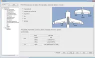
Wing Type

Options of wing types: Wing_Rud_Ele_Ail——conventional modelWing_Delta_Ail/Wing_Flying—— Delta/Flying wingWing_Vtail_Ail——V-TailAUX1: If selected, AIL2 function will be disabled on CH5 AUX2: If selected, ELE2 function will be disabled on CH
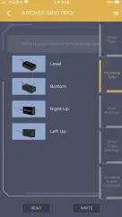
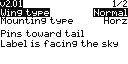
Mounting type
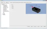
Level, Buttom, Right and Left up options are available.
Gain Setting
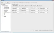
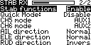
The first partCompensation direction: selecting the travel direction of AIL, AIL2, ELE, ELE2 and RUD. “” means positive and “” means negative.The second partGyro gain: Stabilization ModeThe gain setting under stabilization mode chould be set on the channels related to aileron, elevator and rudder.Angle Gain: Auto Level ModeThe gain setting under automatic level mode could be set on the channels related to aileron and elevator.
Angle Gain: Hover ModeThe gain setting under hover mode could be set on the channels related to elevator and rudder.Angle Gain: Knife Edge ModeThe gain setting under knife edge mode could be set on the channels related to aileron and rudder.\
Note: Optional range is from 0 to 200%. 0, 1, 2 refers to 0%, 100% and 200% respectively.
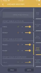
Offset Angle Setting
Due to the possible errors in minor installation and calibration, the function is designed to adjust the attitude of the model. Thus, the user could achieve the best orientation when Auto Level, Hover mode and Knife-edge mode is activated.
Offset Angle of Auto LevelThe angle of roll and pitch could be adjusted on the channels related to aileron and elevator. Straight and Level flight could be realized.Offset Angle of HoverThe nose-up angle could be adjusted on the channels related to aileron and elevator. Stationary hover could be realized in calm weather.Offset Angle of Knife EdgeThe angle of aileron and rudder could be adjusted on the related channels. Straight and level knif-edge flight could be realized.
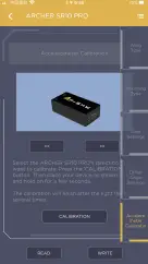
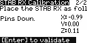
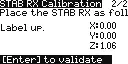
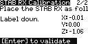
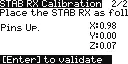
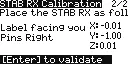
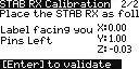
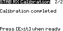
Accelerometer Calibration
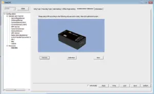
The positive and negative values related to three-axis gyroscope and accelerometer make a total of six values that need to be acquired.Please follow the on-screen instructions.• Click the “Calibration” button and wait until the YELLOW LED flashing, indicating the calibration on this orientation has been completed.• Repeat the above step five times (remaining 5 dimensions). Placing SR6 in the required orientation, ensure all values (X, Y, Z, Mod)are displaying 1.000 with the deviation of ±0.1.• Press “Write” to save the data on SR6 when done.
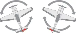
Inspection of flight attitude
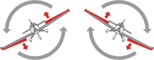 When the plane is rotated left or right (Roll),ailerons should have the correcting actionsas illustrated above.
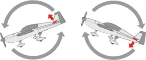 When the plane is rotated up or down (Pitch),elevators should have the correcting actionsas illustrated above.
 When the plane is rotated to left or right(Yaw), rudders should have the correctingactions as illustrated above.
After changing the compensation direction, make sure to check it again on the actual model.
Note: If the compensation direction is incorrect, please reverse the corresponding channel as illustrated below.
Self-check
Attentions• Before self-check, please place the model on the groud (level surface).• When the model is flying, aerodynamic balance is more important than level attitude, which results in that the model flys at a constant altitude with the nose slightly pointing up at low speed. To avoid the nose-diving of the model at high air speed, the user must insure that the model is placed at a level or slightly-nose-up attitude during self-check.• Always install SR6 straight and level in the model. If required, PC software could be used to adjust the angle of attack with the purpose of realizing the required setting. If the values set by the user is bigger than average ones, we advise to recheck the installation orientation of SR6. Steps ( Different from the SXR/R9 STAB OTA/RB series)• Turn on the transmitter and ensure that Ail (CH1), ELE (CH2), RUD (CH4), AIL 2(CH5) and ELE (CH6) are in the neutral position.• Power on the model and start SR6 self-check. Ensure the auto level angle of the gyro and the neutral position of gimbal. Please don’t touch/move the model until self-check finishes, or it may corrupt the calibration settings created during the procedure.• Move the three-position sticks bound to CH12 three times in 2 seconds (up, mid, down). Then the BLUE LED will turn on. Waiting the 8~9 seconds, the LED will flash and move the sticks bound to CH1~CH6(except the CH related to Thr) in 7~8 seconds , the corresponding parts on the model will move . At last, the BLUE LED will turn off,the corresponding parts on the model will move automatically indicating self-check has completed, In the end, SR6 will save the zero points of the gyro, auto level angle, gimbal neutral positionand servo channel limits.• Move the sticks bound to CH1~CH6 (except the CH related to Thr) and check the channel output limits, ensuring that the signal outputs of SR6 will not damage the corresponding parts on the model.
Never operate the stick bound to CH12 during flight session. If so, it will trigger self-check and may cause the crash of the model.
Setup• Calibrate SR6 with the Lua.or Freelink App or the PC software and install it into the model. Insure the settings of wing type and mounting type are identical to the intended model installation.• Turn on the transmitter and reduce the value of servo endpoint setting. Ensure self-check mode will not damage the corresponding parts on the model.• Assign a knob/slider to CH9, then real-time gain adjustment capabilities of SR6 will be activated.• Assign three-position switches to CH10 and CH11 with the purpose of switching available flight modes.• Power on the model and check the deflection direction of each related parts on the model. Make sure the switch assigned to flight modes is correct and the compensation direction of the gyro is set as intended on AIL, RUD and ELE.• Make a self-check for SR6 if necessary. Disconnecting the power on SR6 will not lose the set parameters.
 report this ad
Under identical operating conditions, the value of each channel produced by the assigned switch in FrOS are opposite to that in OpenTX. For exmaple, SW Up in FrOS is equal to SW Down in OpenTX.
FrSky Electronic Co., Ltd. www.frsky-rc.com Contact us: Add: F-4,Building C, Zhongxiu Technology Park, No.3 Yuanxi Road, Wuxi, 214125, Jiangsu, China Technical Support:
References
[xyz-ips snippet=”download-snippet”]