FrSky R9 MX OTA Receiver
Introduction
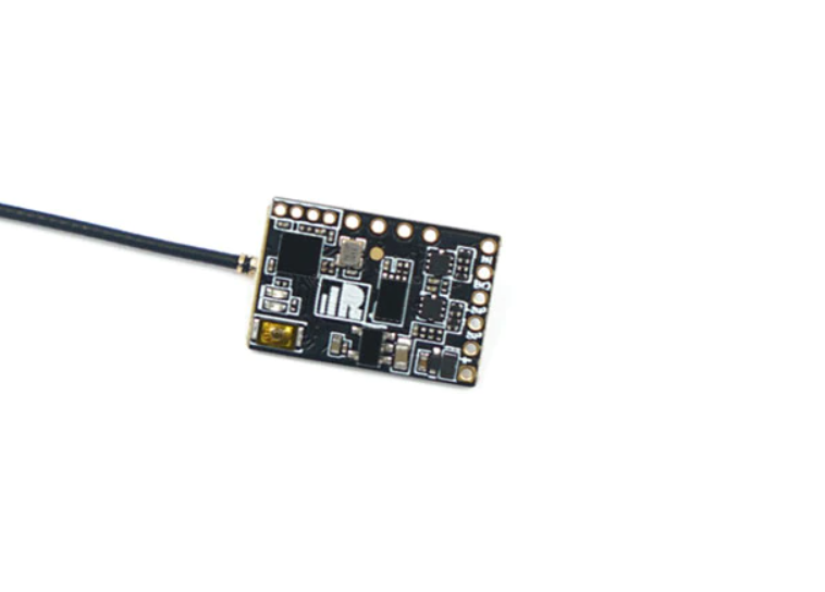
The R9 MX is the enhanced versions of the previous R9 MM/Mini series long-range capable receivers, equivalent in size and weight equipped with a robust detachable Ipex1 antenna connector.
The R9 MX takes features from the previous R9 Mini and R9 MM making it compatible with more external devices by providing an Inverted S. Port output and supporting the redundancy function. Additionally, it retains soldering points to connect 4 PWM channels. The enhanced design proves to be more durable, and in conjunction with the latest ACCESS firmware, the two are now synchronized and we are able to unlock the true potential of the ACCESS protocol.
Overview
Specifications
- Frequency: 868MHz / 915MHz
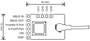
- Dimension: 18*12*3.2mm (L*W*H)
- Weight: 3.2g
- Numbers of Channel: 4 PWM / 16 SBUS (CH16 outputs RSSI)
- Operating Voltage: DC 3.5V~10V
- Operating Current: <
- Compatibility: R9M Lite / R9M Lite Pro / R9M 2019 with ACCESS firmware
Features
- ACCESS protocol and supports OTA functions
- 915MHz / 868MHz long-range with low latency
- Enhanced and durable design
- Support S.Port / F.Port (Configurable in OpenTX / FrOS menu) · With inverted S.Port outputs · Signal redundancy function · Detachable Ipex1 connector antenna
 Smart Port (S. Port) is a signal wire full duplex digital transmission interface developed by FrSky Electronic Co., Ltd. All products enabled with Smart Port (including XJT module, XSR, X6R and X8R receiver, new hub-less sensors, new Smart Dashboard, etc), serial port user data and other user input/output devices can be connected without limitations for numbers or sequences at a high transmission speed.
Registration & Automatic binding (Smart Match TM )
With the FrSky ACCESS protocol, the transmitter/transmitter module can bind receiver without using the “F/S” button. Follow the step below to finish the Registration & binding procedure:
- Put the transmitter/transmitter module into [Reg] status.1.1 For Taranis X-Lite Pro and R9M Lite Pro as an example, turn on the transmitter, go to the MENU-MODEL SETUP-PAGE 2, choose External RF-Mode R9MLP ACCESS, then select [Reg].
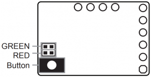
- Connect the battery to the receiver while holding the F/S button on the receiver. The RED LED and GREEN LED on the receiver will be on, indicating into the [Reg] status. Select [ENTER] on the transmitter, The RED LED and GREEN LED on the receiver will flash, and the transmitter displays [Registration ok].
- Turn off the receiver.
- Move the cursor to select the receiver 1 [Bind].
- Connect the battery to the receiver, the GREEN LED on the receiver will be on, indicating into the [Bind] status. Select the RX, and the transmitter displays [Bind successful].
- The transmitter exit [Bind], GREEN LED will flash, RED LED will be off, indicating working normally
About OTA function
— For Taranis X-Lite Pro as an example, go to the SD CARD 2/7, and select the FW, press the enter button, select [Flash receiver by ext. OTA], power on the receiver, select the RX, go to the [ENTER], complete the flash process, the transmitter will display [Flash successful]. Re-power the receiver and wait for 3 seconds, the Green LED starts flashing indicates the receiver works properly at the moment.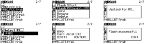 Note: Update the firmware after the receiver gets binded.
How to enable/disable the receiver telemetry
— For Taranis X-Lite Pro as an example, go to the External RF, select the Receiver, press the ENTER button, select the options, and enable/disable the telemetry.
How to switch the F.Port
— For Taranis X-Lite Pro as an example, select the Receiver, press the ENTER button, select the Options, and select F.Port.
How to Set Failsafe mode (on the transmitter)
There are 3 failsafe modes: No Pulse, Hold, Custom
- No Pulse: on loss of signal the receiver produces no pulses on any channel. To use this type, select it in the menu and wait 9 seconds for the failsafe to take effect.
- Hold: the model will maintain the last position after the signal is lost. To use this type, select it in the menu and wait 9 seconds for the failsafe to take effect.
- Custom: the customized position of each individual channel. The model will move to the pre-set position after the signal is lost. Move the cursor to “Set” and press ENTER, you will see FAILSAFE SETTING screen below. Move the cursor to the channel you want to set failsafe on, and press ENTER. When moving the corresponding sticks or switches, you will see the channel bar moving. Move the channel bar to the place you want for failsafe and long press ENTER to finish the setting. Wait 9 seconds before the failsafe takes effect.
Note: If failsafe is not set, the model will hold the last position after signal is lost, thus it may fly away or cause injury.
FCC STATEMENT
- This device complies with Part 15 of the FCC Rules. Operation is subject to the following two conditions:1) This device may not cause harmful interference.2) This device must accept any interference received, including interference that may cause undesired operation.
- Changes or modifications not expressly approved by the party responsible for compliance could void the user’s authority to operate the equipment.
NOTE: This equipment has been tested and found to comply with the limits for a Class B digital device, pursuant to Part 15 of the FCC Rules. These limits are designed to provide reasonable protection against harmful interference in a residential installation. This equipment generates uses and can radiate radio frequency energy and, if not installed and used in accordance with the instructions, may cause harmful interference to radio communications. However, there is no guarantee that interference will not occur in a particular installation. If this equipment does cause harmful interference to radio or television reception, which can be determined by turning the equipment off and on, the user is encouraged to try to correct the interference by one or more of the following measures:– Reorient or relocate the receiving antenna.– Increase the separation between the equipment and receiver.– Connect the equipment into an outlet on a circuit different from that to which the receiver is connected.– Consult the dealer or an experienced radio/TV technician for help.
FrSky is continuously adding features and improvements to our products. To get the most from your product, please check the download section of the FrSky website www.frsky-rc.com for the latest update firmware and manuals
FrSky Electronic Co., Ltd.www.frsky-rc.comContact us: [email protected]
Add: F-4,Building C, Zhongxiu Technology Park, No.3 Yuanxi Road, Wuxi, 214125, Jiangsu, China Technical Support: [email protected]

References
[xyz-ips snippet=”download-snippet”]