![]() TV/AM/FM/LTE ROOFTOP ANTENNA WITH CEILING MOUNT BRACKETInstruction Manual
TV/AM/FM/LTE ROOFTOP ANTENNA WITH CEILING MOUNT BRACKETInstruction Manual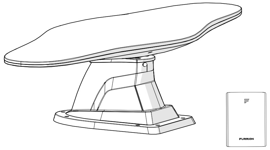 Ceiling Mount Bracket
Model:FAN73B7C-BLFAN73B7C-BL2FAN73B7C-BL3
Welcome
Thank you for purchasing this Furrion® TV/AM/FM/LTE Rooftop Antenna with ceiling mount bracket. Before operating your new product, please read these instructions carefully. This instruction manual contains information for safe use, installation and maintenance of the product. Please keep this instruction manual in a safe place for future reference. This will ensure safe use and reduce the risk of injury. Be sure to pass on this manual to new owners of this product. The manufacturer does not accept responsibility for any damages due to not observing these instructions. If you have any further questions regarding our products, please contact us at [email protected]
Supplier’s Declaration of Conformity47 CFR § 2.1077 Compliance InformationUnique IdentifierTrade Name: FurrionModel No.: FAN73B7C-BL, FAN73B7C-BL2, FAN73B7C-BL3Responsible Party U.S. Contact InformationFurrion Innovation Center & Institute of Technology52567 Independence Ct., Elkhart, IN 46514, USAToll free:1-888-354-5792; Email: [email protected]
FCC Compliance StatementThis device complies with Part 15 of the FCC Rules. Operation is subject to the following two conditions: (1) This device may not cause harmful interference, and (2) this device must accept any interference received, including interference that may cause undesired operation.
Industry Canada StatementThis Class B digital apparatus complies with Canadian ICES-003.CAN ICES-3 (B)/NMB-3(B)
Product Overview
Product Features
- Compatible with HDTV of various digital terrestrial signals (DVB-T, ISDB-T, DTMB, ATSC), stereo and FM/AM radios.*
- The waterproof housing is UV resistant, and is designed for superior durability using injection mold.
- Omni directional antennas receive VHF, UHF, FM and AM signal from every point regardless of the direction you are traveling.
- Built-in high gain and low noise amplifier.
- The antenna is surface-treated to withstand impact from all weather conditions.
- SMT Technology and micro-electronics ensure excellent antenna performance.
 *FAN73B7C-BL2 and FAN73B7C-BL3 are compatible with KeyTV.** The outline of the antenna base equipped with FAN73B7C-BL3 is slightly different.
 *FAN73B7C-BL2 and FAN73B7C-BL3 are compatible with KeyTV.** The outline of the antenna base equipped with FAN73B7C-BL3 is slightly different.
Installation
Do not install couplers, splitters, etc. between the power supply and the antenna. Installation of any item on the downlead may cause a short in the system. The downlead supplies +12VDC to the preamp in the antenna. The power supply should be turned OFF when connecting or disconnecting cables to the power supply and antenna, but should be turned ON during voltage testing.
What’s in the Box
Make sure you have the following items included in the packaging. If any items are damaged or missing, contact your dealer.
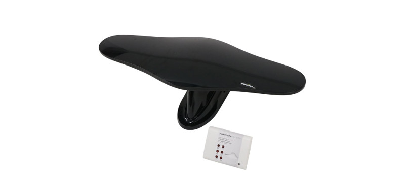
- TV Antenna Wing x 1
- Antenna Base x 1
- Ceiling mount bracket x 1
- 4 x 12 mm square socket pan head tapping screws x 2
- Warranty Card x 1
- Instruction Manual x 1
Mounting the Antenna
There are two ways of installing the rooftop antenna:
- Method 1 – Making a new opening. In this case the ceiling of the RV must be accessible.
- Method 2 – Using the existing opening in the vehicle roof.
Making a New Opening
1. Select a flat location where there is sufficient area to mount and seal the antenna to the roof surface. Do not install the antenna next to any other device on the rooftop.
2. Mark a basic hole outline on the RV rooftop using the antenna base as a template. (Fig. 1)*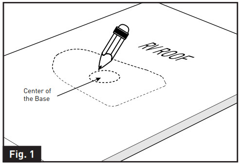
3. Drill a 2″ (50mm) circle hole in the RV roof using a hole saw. (Fig. 2)** *, ** The outline of the antenna base equipped with FAN73B7C-BL3 is slightly different.
4. Thread the cables of the LTE antenna base through the opening. Put the LTE antenna base over the opening area. (Fig. 3)NOTE: Make sure the center hole of the LTE antenna is aligned with the hole in the RV roof.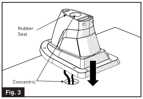 5. Fix the LTE antenna base on the RV roof using seven stainless steel selftapping screws and tighten using a screwdriver. (Fig. 4)***NOTE: Do not overtighten as damage to the base may occur, which will void the warranty. A screw angle up to 30 degrees is acceptable without damaging the base.
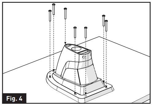 *** For FAN73B7C-BL3, six screws are needed.6. Insert the bottom collar of the TV antenna wing into the center hole of the LTE antenna base. (Fig. 5) Make sure the rubber seal on top of the LTE antenna base is in location.
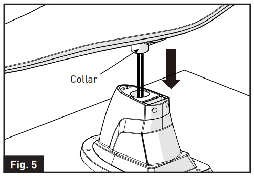 7. Fix the TV antenna wing in the LTE antenna base using the two 4 x 12mm square socket pan head tapping screws provided with the product. (Fig. 6)
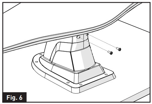 8. Apply a liberal amount of sealant around the antenna base and the screw holes to prevent water leakage if necessary. Check with the RV manufacturer for the standard sealant for the vehicle. (Fig. 7)
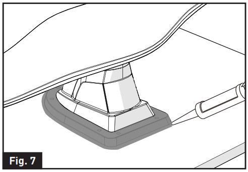 9. Follow the wiring guidelines below to connect the cables of TV/FM antenna (black) and FM/AM antenna (white) from the interior of the RV ceiling. See “Wiring Diagram” section for detail.– TV/FM antenna (Black) with extension cable to DC powered wall-plate.– FM/AM antenna (White) to audio system.
Using the Existing Opening
- Unscrew and remove the old TV antenna from the RV rooftop.
- Remove all caulking compound around the opening.
- Insert the bottom collar of the TV antenna wing into the center hole of the antenna base.NOTE: Make sure the rubber seal on top of the LTE antenna base is in location. (Fig. 8)
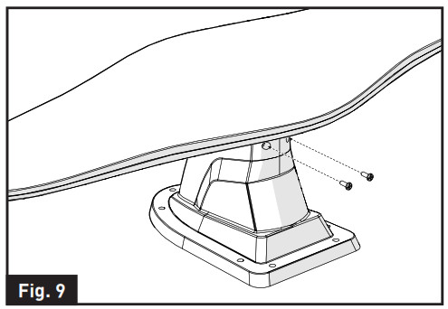
- Fix the TV antenna wing in the base using the two 4 x 12mm square socket pan head tapping screws provided with the product. (Fig. 9)
- Following the guidelines below to connect the cables of TV/FM antenna (black) and FM/AM antenna (white) from the interior of the RV ceiling. See “Wiring Diagram” section for detail.– TV/FM antenna (Black) with extension cable to DC powered wall-plate.– FM/AM antenna (White) to audio system.
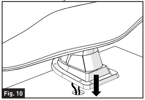
- Thread the cables of the antenna base through the opening. (Fig. 10)NOTE: Make sure the middle circle of the LTE antenna is center aligned with the cutting hole in the RV roof.
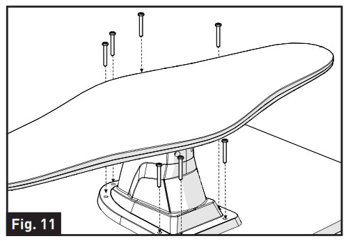
- Fix the antenna base on the RV roof using seven stainless steel selftapping screws and tighten using a screwdriver. (Fig. 11)****NOTE: Do not overtighten as damage to the base may be occur, which will void the warranty. A screw angle up to 30 degrees is acceptable without damaging the base.
- Apply a liberal amount of sealant around the antenna base and the screw holes to prevent water leakage if necessary. Check with the RV manufacturer for the standard sealant for the vehicle. (Fig. 12)**** For FAN73B7C-BL3, six screws are needed.Installing the Ceiling Mount BracketNOTE: It is recommended that you have all the wires connected before permanently installing the ceiling mount bracket onto the rooftop. See ‘Wiring Diagram’ section on how to connect the wires.1. Push to remove the top cover of the ceiling mount bracket. (Fig. 13)2. Follow the wiring guidelines below to connect the cables from the interior of the RV ceiling. See “Wiring Diagram” section for detail. Fix the wires with nylon cable tie. (Fig. 14)– LTE Antennas: Connect to the rooftop unit by mapping the same wire color.– Power Wires: Connect to the RV +12Vdc (current rating >1A) power source. Red is power wire, Black is ground wire.– Network Wires: Connect to the network interface in the RV.3. Cover the base of the ceiling mount bracket over the cutout area and secure with eight stainless steel selftapping screws (not supplied). (Fig. 15)4. Place back the top cover to the ceiling mount bracket. (Fig. 16)

 Installing the Ceiling Mount BracketNOTE: It is recommended that you have all the wires connected before permanently installing the ceiling mount bracket onto the rooftop. See ‘Wiring Diagram’ section on how to connect the wires.1. Push to remove the top cover of the ceiling mount bracket. (Fig. 13)
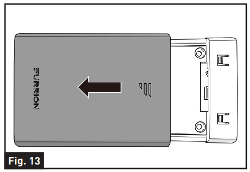 2. Follow the wiring guidelines below to connect the cables from the interior of the RV ceiling. See “Wiring Diagram” section for detail. Fix the wires with nylon cable tie. (Fig. 14)– LTE Antennas: Connect to the rooftop unit by mapping the same wire color.– Power Wires: Connect to the RV +12Vdc (current rating >1A) power source. Red is power wire, Black is ground wire.– Network Wires: Connect to the network interface in the RV.
 3. Cover the base of the ceiling mount bracket over the cutout area and secure with eight stainless steel selftapping screws (not supplied). (Fig. 15)
 4. Place back the top cover to the ceiling mount bracket. (Fig. 16)
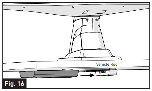
Mounting the Wall PlateThe wall plate may be flush-mounted in most standard electrical boxes.
- Select a suitable location that is not susceptible to moisture.
- Mark and cut a hole in the RV wall.
- Connect the antenna cables to the wall plate. See `Wiring Diagram’ for detail info.
- Fix the wall plate in the wall using 2 stainless steel self-tapping screws (not included).NOTE: The wall plate is sold separately, please contact the dealer for detail.
Connections
Wiring Diagram
Refer to accessories page for planning connections. WARNING: The wall plate should be turned off while connecting cables. Connect the cables from the antenna to distribution wall plate and to the FM radio (AM Radio needs to connect the FM/AM antenna from the rooftop unit). Connect the power cables from the distribution wall plate according to the diagram below.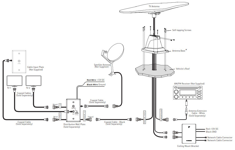
Testing the Power Supply
Make sure your TV set is working properly.
- Disconnect the cable from the antenna jack on the power supply and check for +12VDC. If +12VDC is present, there is a cable problem connecting the power supply to the antenna, repair/replace the cable. If +12VDC is not present at the antenna jack, be sure the indicator light is ON. If not, check the polarity of the red/white wires and the +12VDC source.* The outline of the antenna base equipped with FAN73B7C-BL3 is slightly different.
Operation
Running a Channel Scan
To receive maximum number of channels, a channel scan is required once the antenna and power supply have been correctly installed and all cables have been properly connected. A new scan might find any new channels that have been added in your area or find any channels that have been changed or moved since the last scan.NOTE: Antenna reception may vary based on transmitting antenna tower height, lobe pattern of the transmitter, height of the receiving antenna, weather conditions and terrain on receiving path, including trees, buildings and hills. The steps to perform a channel scan may vary between televisions or compatible devices. Always run a channel scan in the following situations:
- Anytime the antenna is moved or enters a new region
- Anytime a channel is lost.
Selecting TV Antenna Reception
To receive TV antenna reception, press the ON/OFF switch and the power indicator will be lit.*
Selecting Cable TVNOTE: The vehicle must be connected to an external cable source.To receive cable TV, press the ON/OFF switch and the power indicator will be turned off.**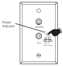
*, ** Skip the step of pressing the ON/OFF switch when a KeyTV system is installed.
Specifications
| Technical Specification | |||
| MODEL | FAN73B7C-BL | FAN73B7C-BL2
FAN73B7C-BL3 |
|
| OPERATING CONDITION | |||
| VOLTAGE | 9-16Vdc, 12Vdc typical | ||
| CURRENT CONSUMPTION | <100mA @ 12V | ||
| AM/FM ANTENNA | |||
| AM FUNCTION | Frequency Range | 520kHz to 1710kHz | |
| Radiation Direction | Omni – direction | ||
| FM FUNCTION | Antenna Gain | 15dB Max | 10dB Max |
| Max. output level | 106dBμV | ||
| Frequency Range | 87.5MHz – 108MHz | ||
| Radiation Direction | Omni – direction | ||
| Impedance | 75ohm | ||
| Noise Figure | <7dB | <11dB | |
| TV ANTENNA | |||
| UHF FUNCTION | Antenna Gain | 28dB Max | |
| Max. output level | 105dBμV | ||
| Frequency Range | 470MHz to 700MHz | ||
| Radiation Direction | Omni – direction | ||
| Impedance | 75ohm | ||
| Noise Figure | <6dB | ||
| FM / VHF
FUNCTION |
Antenna Gain | 20dB/24 dB Max | 15dB Max |
| Max. output level | 106dBμV | ||
| Frequency Range | 47MHz – 230MHz | ||
| Radiation Direction | Omni – direction | ||
| Impedance | 75ohm | ||
| Noise Figure | <7dB | <11dB |
![]() Furrion Innovation Center & Institute of Technology● 52567 Independence Ct., Elkhart, IN 46514, USA● Toll-free: 1-800-789-3341● Email: [email protected]
Furrion Innovation Center & Institute of Technology● 52567 Independence Ct., Elkhart, IN 46514, USA● Toll-free: 1-800-789-3341● Email: [email protected]
©2007-2020 Furrion Ltd. Furrion® and the Furrion logo are trademarks licensed for use by Furrion Ltd. and registered in the U.S. and other countries.Patents pending (FAN73B7C-BL)FURRION.COMIM-FAV00029 V6.0
References
[xyz-ips snippet=”download-snippet”]