FUSION Apollo MS-WB670 Instructions
Important Safety Information
![]() WARNING
WARNING
Failure to follow these warnings and cautions could result in personal injury, damage to the vessel, or poor product performance.See the Important Safety and Product Information guide in the product box for product warnings and other important information. This device must be installed according to these instructions.Disconnect the vessel’s power supply before beginning to install this product.Before applying power to this product, make sure it has been correctly grounded according to these instructions.
![]() CAUTION
CAUTION
To avoid possible personal injury, always wear safety goggles, ear protection, and a dust mask when drilling, cutting, or sanding.
NOTICE:
When drilling or cutting, always check what is on the opposite side of the surface to avoid damaging the vessel.Do not use the stereo as a template when drilling the mounting holes because this may damage the glass display and void the warranty. You must only use the included template to correctly drill the mounting holes.You must read all installation instructions before beginning the installation. If you experience difficulty during the installation, contact Fusion® Product Support.
What’s In the Box
- Four 8-gauge, self-tapping screws
- Power and speaker wiring harness
- Auxiliary-in, line-out, and subwoofer-out wiring harnesses
- NMEA 2000® drop cable
Tools Needed
- Phillips screwdriver
- Electric drill
- Drill bit (size varies based on surface material and screws used)
Mounting Considerations
![]() CAUTION
CAUTION
In high ambient temperatures and after extended use, the device enclosure may reach temperatures deemed dangerous to touch. As a result, the unit must be installed in a location where it cannot be touched during operation.
NOTICE
This device should be mounted in a location that is not exposed to extreme temperatures or conditions. The temperature range for this device is listed in the product specifications. Extended exposure to temperatures exceeding the specified temperature range, in storage or operating conditions, may cause device failure. Extreme-temperature-induced damage and related consequences are not covered by the warranty.
When selecting a mounting location for the device, observe these considerations.
- You must mount the device in a location where it is not submerged.
- You must mount the device in a location with adequate ventilation where it is not exposed to extreme temperatures.
- You should mount the device so the cables can be connected easily.
- To achieve IPX2 water ingress protection, you must mount the device on a vertical surface with the connectors pointing downward.
- You can mount the device on a horizontal surface, but such positioning might not achieve IPX2 water ingress protection.
- To avoid interference with a magnetic compass, you must mount the device at least 15 cm (6 in.) away from a compass.
Mounting the Device
NOTICEIf you are mounting the device in fiberglass, when drilling the pilot holes, use a countersink bit to drill a clearance counterbore through only the top gel-coat layer. This will help to avoid cracking in the gel-coat layer when the screws are tightened.
NOTE: Screws are included with the device, but they may not be suitable for the mounting surface. Before you mount the device, you must select a mounting location, and determine what screws and other mounting hardware are needed for the surface.
- Place the device in the mounting location, and mark the location of the pilot holes.
- Drill a pilot hole for one corner of the device.
- Loosely fasten the device to the mounting surface with one corner, and examine the other three pilot-hole marks.
- Mark new pilot-hole locations if necessary, and remove the device from the mounting surface.
- Drill the remaining pilot holes.
- Secure the device to the mounting location.
Connection Considerations
For the stereo to function correctly, you must connect it to power, to speakers, and to input sources. You should carefully plan the layout of the stereo, speakers, input sources, optional NMEA 2000 network, and optional Fusion PartyBus™ devices or network before making any connections.
Port Identification
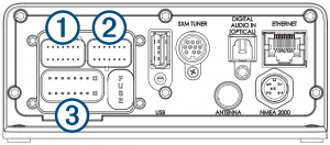
| Item | Description |
| 1 |
Connects the stereo to the wiring harness for zone 3. |
| 2 |
Connects the stereo to the wiring harness for auxiliary input 1, and for the line and subwoofer outputs for zones 1 and 2. |
| 3 |
Connects the stereo to the power and speaker wiring harness. |
| FUSE |
Contains the 15 A fuse for the device. |
| USB |
Connects the stereo to a USB source. |
| SXM TUNER |
Connects the stereo to a SiriusXM® Connect Tuner to receive SiriusXM stations where available (not included). Connects to a Fusion DAB module to receive DAB stations where available (not included). |
| DIGITAL AUDIO IN (OPTICAL) |
Connects the stereo to an optical digital audio source, such as TV or DVD player. |
| ETHERNET |
Connects the stereo to another Fusion PartyBus stereo, zone stereo, or network . |
| ANTENNA |
Connects the stereo to a typical AM/FM antenna.If you are installing the stereo on a boat with a metal hull, you must use a ground- dependent antenna. If you are installing the stereo on a boat with a non-metal hull, you must use a ground-independent antenna. See the installation instructions provided with your antenna for more information. |
| NMEA 2000 |
Connects the stereo to a NMEA 2000 network. |
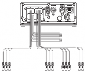
Wiring Harness Wire and Connector Identification
|
Wire or RCA Connector Function |
Bare Wire Color or RCA Label Name: |
Notes |
|
Ground (-) |
Black |
Connects to the power source. |
|
Power (+) |
Yellow |
Connects to the power source |
|
Ignition |
Red |
Connects to the power source. |
|
Amplifier on |
Blue |
Connects to optional external amplifiers, enabling them to turn on when the stereo turns on. A connected amplifier must use the same ground (-) as the stereo for this signal wire to function correctly. |
|
Telemute |
Br own |
Activates when connected to ground.For example, when you connect this wire to a compatible, hands-free mobile kit, the audio mutes or the input switches to AUX when a call is received and the kit connects this wire to ground. You can enable this functionality from the settings menu. |
|
Dim |
Orange | This wire is not used when installing this device. |
| Speaker zone 1 left (+) |
White |
|
|
Speaker zone 1 left (-) |
White/black |
|
|
Speaker zone 1 right (+) |
Gray |
|
|
Speaker zone 1 right (-) |
Gray/black |
|
|
Speaker zone 2 left (+) |
Green |
|
|
Speaker zone 2 left (-) |
Green/black |
|
|
Speaker zone 2 right (+) |
Purple |
|
|
Speaker zone 2 right (-) |
Purple/black |
|
| Zone 1 line out (left) Zone 1 line out (right) |
ZONE 1 |
Provides output to an external amplifier, and is associated with the volume control for zone 1. |
|
Wire or RCA Connector Function |
Bare Wire Color or RCA Label Name |
Notes |
|
Zone 1 subwoofer out |
ZONE 1 SUB OUT |
Each subwoofer cable provides a single mono output to a powered subwoofer or subwoofer amplifier. |
|
Zone 2 line out (left) Zone 2 line out (right) Zone 2 subwoofer out |
ZONE 2
ZONE 2 SUB OUT |
Provides output to an external amplifier, and is associated with the volume control for zone 2.Each subwoofer cable provides a single mono output to a powered subwoofer or subwoofer amplifier. |
| Auxiliary in left Auxiliary in right | AUX IN |
Provides an RCA stereo line input for audio sources, such as a CD or MP3 player. |
|
Zone 3 line out (left) Zone 3 line out (right) Zone 3 subwoofer out |
ZONE 3 |
Provides output to an external amplifier, and is associated with the volume control for zone 3.Each subwoofer cable provides a single mono output to a powered subwoofer or subwoofer amplifier. |
Power Connection
When connecting the stereo to power, you must connect the yellow, red, and black wires to the power source. The yellow and red wires have different functions, and the method you use to connect them to power depends on how you plan to use the stereo on your vessel.
Yellow wire
- This wire provides power to the stereo.
- This wire should be connected through a 15 A circuit breaker, if one is available on the vessel.NOTICEIf a 15 A circuit breaker is not available on the vessel, you must connect this wire to power through a 15 A fuse (not included).
- This wire provides power to the stereo at all times, and it will drain the battery even when the stereo is not in use. You should install a manual switch on this wire if a 15 A circuit breaker is not available on the vessel, or if you cannot toggle the breaker to remove power to the stereo when storing the vessel.
- If it is necessary to extend this wire, use 14 AWG (2.08 mm2 ) wire. For extensions longer than 1 m (3 ft.), use 12 AWG (3.31 mm² ) wire.
Red wire
- This wire can be connected to the same power source as the yellow wire through the ignition or through a manual switch. This enables you to turn the stereo on and off automatically when you turn the vessel on and off, or when you activate the switch.
- Using this wire to turn the stereo on and off behaves in the same way as using the power button on the stereo to turn it on and off. It is not necessary to connect this wire to a switch if you plan to toggle the power using the power button on the stereo or using a connected chartplotter or remote control. This wire must be connected to turn the stereo on.
- When you turn off the stereo using this switch or the power button, it enters a standby mode that allows the stereo to start up again faster than if you switch the power off using the yellow wire. When it is in standby mode, the stereo uses up to 200 mA, and you must turn off power to the stereo on the yellow wire thorough the circuit breaker or manual switch when you are not using the vessel to avoid draining the battery.NOTICEYou must connect this wire to power through a 1 A fuse (not included), whether or not you connect it to the ignition or manual switch.
- If it is necessary to extend this wire, use 22 AWG (0.33 mm2 ) wire.
Black wire
- This is the ground wire, and you must connect it to the negative terminal of the power source or to a common ground.
- If it is necessary to extend this wire, use 14 AWG (2.08 mm2 ) wire. For extensions longer than 1 m (3 ft.), use 12 AWG (3.31 mm² ) wire.
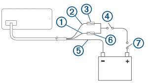
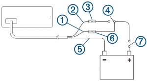
Connecting to Power Without Using an Ignition Switch
This method of connection is used most often on larger vessels and on vessels with multiple networked stereos and other marine devices. For these installations, a faster startup time is typically less critical, and it is more effective to use the breaker or a dedicated switch on the electrical panel to turn off the stereo and ensure that no unexpected power drain occurs.
- Consult this diagram to plan the wire connections.

- Route all wires to the stereo wiring harness, the circuit breaker or switch, and the power source as necessary.Do not connect the wiring harness to the stereo until after you have made all of the bare wire connections.
- Install all of the necessary fuses on the red and yellow wires.
- Connect the wiring harness to the stereo.When the circuit breaker or manual switch is closed, the stereo is always on. You can use the power button on the stereo or a connected chartplotter or remote control to place the stereo in a low-power standby mode if needed.
|
Item |
Description |
Notes |
|
1 |
Yellow wire |
You should connect this wire to the red wire before you connect both wires to the manual switch or circuit breaker. |
|
2 |
Red wire |
You should connect this wire to the yellow wire so that it does not act as a physical standby switch. |
|
3 |
1 A fuse (not included) |
You must install this fuse on the red wire before you connect the red wire to the yellow wire. |
|
4 |
Manual switch (optional) |
This switch is needed only if a circuit breaker is not available or if it provides a more convenient method of cutting power to the stereo. |
|
5 |
Black wire |
Ground (-) |
| 6 | 15 A fuse (not included) |
This fuse is required if you are not able to connect to power through a 15 A circuit breaker . |
|
7 |
15 A circuit breaker |
If a circuit breaker is not available, you must connect a 15 A fuse on the yellow wire |
NOTE: When you are not using the vessel, you should remove power to the stereo using the circuit breaker or manual switch to avoid draining the battery.
Connecting to Power Through an Ignition Switch
This method of connection is used most often on ski boats, wake boats, and similar sport or recreational vessels where power to the engines is toggled often. For these installations, a quick standby and faster startup time is desired so that music can be stopped and begin playing again as quickly as possible after restarting the engines. When in standby mode, the stereo uses up to 200 mA, and you should connect the power wires through a circuit breaker or manual switch to avoid draining the battery when you are not using the boat.
- Consult this diagram to plan the wire connections
- Route all wires to the stereo wiring harness, the ignition or ACC switch, the circuit breaker, and the power source as necessary.Do not connect the wiring harness to the stereo until after you have made all of the bare wire connections.
- Install all of the necessary fuses on the red and yellow wires.
- Connect the wiring harness to the stereo.When you turn on the ignition switch, the stereo turns on along with other accessory electronics. When you turn off the ignition switch, the stereo enters a low-power standby mode.
|
Item |
Description |
Notes |
|
1 |
Yellow wire |
You must connect this wire to the same power source as the ignition or ACC switch. |
|
2 |
Red wire |
You must connect this wire to the ignition or ACC switch before you connect it to the same power source as the yellow wire. |
|
3 |
1 A fuse (not included) |
You must install this fuse on the red wire before you connect the red wire to the ignition or ACC switch. |
|
4 |
Ignition or ACC switch |
Connecting the red wire to this switch allows the stereo to enter a low- power standby mode when you turn off the engines, so it can start up faster when you turn on the engines again. |
|
5 |
Black wire |
Ground (-) |
|
6 |
15 A fuse (not included) |
This fuse is required if you are not able to connect to power through a 15 A circuit breaker . |
|
7 |
15 A circuit breaker or manual switch |
If a circuit breaker is not available, you must connect a 15 A fuse on the yellow wire. You should also connect the yellow wire to power using a manual switch, so you can remove power to the stereo when you are not using the boat. |
NOTE: When you are not using the vessel for an extended period of time, you should remove power to the stereo using the circuit breaker or other manual switch on the yellow wire to avoid draining the battery.
Speaker Zones
You can group speakers in one area into a speaker zone. This enables you to control the audio level of the zones individually. For example, you could make the audio quieter in the cabin and louder on deck. Up to two pairs of speakers can be connected per channel of each zone, in parallel. One zone can support no more than four speakers using the on-board amplifier. Zones 1 and 2 are powered by the on-board amplifier. Zone 3 is available as a line-level output only. To use the RCA line output and the RCA subwoofer output for zone 3, you must connect an external amplifier. You can set the balance, volume limit, tone, subwoofer level, subwoofer frequency, and name for each zone, and configure other zone-specific settings.
Single-Zone System Wiring Example
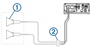
1. Speakers2. Water-tight connection
Speaker System Wiring Using a Line Out
This diagram illustrates a system installation with an external amplifier and subwoofer connected to zone 2 on the stereo using a line out. You can connect an amplifier and subwoofer to any or all of the available zones on the stereo.
NOTE: You can connect speakers to the speaker wires for the internal stereo amplifier while using the line out on zones 1 and 2, although adjusting the volume affects both the speakers connected to the internal amplifier and the line out. This may result in uneven volume levels.
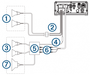
- Zone 1 speakers
- Water-tight connection
- Zone 2 speakers
- Amplifier-on signal wire You must connect this wire to each amplifier connected to a zone line out. A connected amplifier must use the same ground (-) as the stereo for this signal wire to function correctly.Powered amplifier connected to the zone 2 line out
- Zone 2 line out and subwoofer out Each subwoofer cable provides a single mono output to a powered subwoofer or subwoofer amplifier. You may need to use an RCA splitter to connect this to an amplifier.
- Subwoofer
Connecting a SiriusXM Tuner Module
This device is compatible with a SiriusXM SXV300 or newer vehicle tuner module.
- If you have already connected a USB source, disc onnect it from the stereo.
- Connect the cable from the SiriusXM tuner module to the SXM TUNER port on the back of the stereo.
- Follow the instructions provided with the SiriusXM tuner module and antenna to complete the SiriusXM installation.
- If necessary, reconnect the USB source.
- Complete the stereo installation.
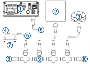
1 Stereo2 Supported chartplotter, MFD, or compatible Fusion NMEA 2000 remote control3 NMEA 2000 GPS antenna, speed sensor, or wind instrument.When the stereo is connected to the same NMEA 2000 network as a compatible engine, a GPS antenna, a chartplotter with a built-in GPS antenna, a wind instrument, or a water speed sensor, it can be configured to automatically adjust the volume according to the engine RPM, the speed over ground, the wind speed, or the speed through water. See the stereo Owner’s Manual for more information.4 In-line switch5 NMEA 2000 power cable6 NMEA 2000 drop cable, up to 6 m (20 ft.)7 9 to 16 Vdc power supply8 NMEA 2000 terminator or backbone cable9 NMEA 2000 T-connector10 NMEA 2000 terminator or backbone cable’
Fusion PartyBus Networking
The Fusion PartyBus networking feature allows you to connect multiple compatible stereos together on a network, using a combination of wired or wireless connections. You can group a compatible stereo, such as the Apollo WB670 stereo, with other compatible stereos connected to the network. Grouped stereos can share available sources and control media playback on all of the stereos in the group, which allows for a synchronized audio experience across the vessel. You can quickly create, edit, and break up groups as needed from any compatible stereo or remote control on the network.
NOTE: A zone stereo, such as the Apollo SRX400, can create or join a group to control and play sources from other stereos, but it cannot share its sources with the group. For additional considerations when sharing sources, see the owner’s manual. You can use compatible stereos and remote controls, whether they are grouped or not, to adjust the volume of the available speaker zones for any stereo on the network.
Wired Networking Considerations
Wired Networking Considerations When you are planning your network installation, observe the following considerations for all wired connections.
- You must connect devices using standard Cat5e or Cat6 network cables with RJ45 connectors.
- You can use one network cable to directly connect two compatible devices.
- You must use wired network switches and wired or wireless network routers when you connect more than two compatible devices to a network.
- f you install a router on the network, it should be configured to be a DHCP server by default. See your router instructions for more information.
- If you do not install a router, and there are no other DHCP servers on the network, you should configure one Fusion PartyBus stereo to be a DHCP server.
Wired Network Example for Direct Connections
No network setting changes are needed when connecting two devices together directly.
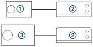
1 Fusion PartyBus zone stereo or remote control2 Apollo MS-WB670 stereo3 Fusion PartyBus stereo
Wired Network Example with a Switch or Router
You must use wired network switches, a wired network router, or both to connect more than two Fusion PartyBus devices.No network setting changes are needed when connecting multiple Fusion PartyBus devices using a switch, but if you are using a router, you may need to configure it to be a DHCP server. See your router instructions for more information.
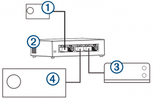
1 Fusion PartyBus zone stereo or remote control2 Wired network switch or wired network router3 Apollo MS-WB670 stereo4 Fusion PartyBus stereo
Constructing a Network
You should have a basic understanding of networking when building a network for Fusion PartyBus devices. These instructions guide you through the basics of building and configuring a network, and should apply to most situations. If you need to perform advanced networking tasks, such as assigning static IP addresses to devices on the network or configuring advanced settings on a connected router, you may need to consult a networking professional.
- Determine the installation location of the Fusion PartyBus devices you want to connect to the network.NOTE: Wired connections are more reliable than wireless connections. When planning your network, you should run network cables instead of using wireless connections when possible.
- Determine the installation location of any needed network routers or switches.
- Route Cat5e or Cat6 network cable to the installation locations of the stereos, switches, and router.
- Connect the network cables to the stereos, switches, and router.NOTICEDo not completely install the stereos yet. You should test the network before you install the stereos.
- Turn on all devices connected to the network, including wireless devices.
- If you are using a network router (wired or wireless), consult the documentation provided with your router to configure the router as the DHCP server, if necessary. All stereos should use their default configuration (DHCP CLIENT).
- Test the network by selecting > GROUPS to view a list of devices connected to the on the network, and select an option:
- If any devices are not available to the network, troubleshoot the network Network Troubleshooting.
- If all devices are available to the network, complete the installation for each stereo, if necessary.
Network Configuration
Setting the Stereo as the DHCP Server
If you connected more than two network devices together directly or using a network switch or wireless access point and did not install a router, you should configure only one Fusion PartyBus stereo to be a DHCP server.
- Select > SETTINGS.
- Select the name of the stereo.
- Select NETWORK > STATIC IP > SAVE.
- Select ADVANCED > DHCP SERVER > DHCP ENABLED > SAVE.
Configuring the Stereo for use with a Garmin® Marine Network
You can connect this stereo to a Garmin Marine Network in order to view and control the stereo using a compatible Garmin chartplotter.NOTE: When you configure the stereo for use with a Garmin Marine Network, you are limited to using only Garmin and Fusion devices. You may not be able to use third-party routers, storage devices, or other network products with this stereo directly.When the stereo is connected to a Garmin Marine Network, you can connect a smartphone to a wireless access point on a connected Garmin chartplotter and use the Fusion-Link™ app to control the stereo.
- Select > SETTINGS.
- Select the name of the stereo.
- Select NETWORK > GARMIN MARINE NETWORK.
Resetting Network SettingsYou can reset all network settings for this stereo to the factory default values.
- Select > SETTINGS.
- Select NETWORK > ADVANCED > RESET > YES.
Advanced Network ConfigurationYou can perform advanced networking tasks on a Fusion PartyBus device, such as defining DHCP ranges and setting static IP addresses. See the owner’s manual for more information.
Network Troubleshooting
If you cannot see or connect to Fusion PartyBus devices on the network, check the following:
- Verify that only one device, either a stereo or a router, is configured as a DHCP server.
- Verify that all Fusion PartyBus devices, network switches, routers, and wireless access points are connected to the network and turned on.
- Verify that wireless Fusion PartyBus devices are connected to a wireless router or wireless access point on the network.NOTE: Wired connections are more reliable than wireless connections. If possible, you should connect devices to the network using an Ethernet cable.
- You may experience wireless interference if there are many nearby wireless access points. Change the channel on your router or wireless access point to test for and correct interference.
- Connecting a Bluetooth® device to a stereo configured as a wireless access point or client may reduce wireless performance. Disconnect Bluetooth devices to test for and correct interference.
- If you configured static IP addresses, verify that every device has a unique IP address, that the first three sets of numbers in the IP addresses match, and that the subnet masks on every device are identical.
- If you have made configuration
Stereo Information
Specifications
|
Weight |
475 g (16.75 oz.) |
|
Water rating |
IEC 60529 IPX21 |
|
Operating temperature range |
From 0 to 50°C (from 32 to 122°F) |
|
Storage temperature range |
From -20 to 70°C (from -4 to 158°F) |
|
Input voltage |
From 10.8 to 16 Vdc |
|
Current (max.) |
15 A |
|
Current (muted) |
Less than 700 mA |
|
Current (off) |
Less than 100 mA |
|
Fuse |
15 A mini blade-type |
|
NMEA 2000 LEN @ 9 Vdc |
1 (50 mA) |
|
Bluetooth wireless range |
Up to 10 m (30 ft.) |
|
ANT® wireless range |
Up to 3 m (10 ft.) |
|
Wireless frequencies/protocolsc |
2.4 GHz @ 12 dBm nominal ANT 2.4 GHz @ 7 dBm nominal |
|
Compass-safe distance |
15 cm (6 in.) |
On-board, Class D amplifier
|
Output music power per channel |
4 x 70 W max. 2 ohm |
|
Total output peak power |
280 W max. |
|
Output power per channel |
4 x 43 W RMS at 14.4 Vdc input, 2 ohm, 10% THD2 4 x 26 W RMS at 14.4 Vdc input, 4 ohm, 10% THD2 |
|
Line output level (max.) |
5.5 V (peak to peak) |
|
Aux input level (typical) |
1 V RMS |
Stereo Dimension Drawings
Side Dimensions
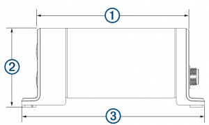
1 107 mm (4.21 in.)2 55 mm (2.17 in.)3 130 mm (5.10 in.)
Top Dimensions
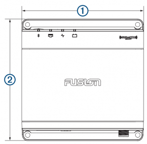
1 130 mm (5.10 in.)2 130 mm (5.10 in.)
Software Updates
Go to support.garmin.com to find software updates and information for your device.
 © 2020 Garmin Ltd. or its subsidiariesGarmin® , ANT® , Fusion® , and the Fusion logo are trademarks of Garmin Ltd. or its subsidiaries, registered in the USA and other countries. Apollo™, Fusion-Link™, and Fusion PartyBus™ are trademarks of Garmin Ltd. or its subsidiaries. These trademarks may not be used without the express permission of Garmin.
Apple® is a trademark of Apple Inc., registered in the USA and other countries. App StoreSM is a service mark of Apple Inc., registered in the USA and other countries. Android™ and Google Play™ are a trademarks of Google Inc. Bluetooth® word mark and logos are owned by the Bluetooth SIG, Inc. and any use of such marks by Garmin is under license. NMEA 2000® and the NMEA 2000 logo are registered trademarks of the National Marine Electronics Association. SiriusXM® and all related marks and logos are trademarks of Sirius XM Radio Inc. All rights reserved.M/N: A03924IC: 1792A-03924
References
[xyz-ips snippet=”download-snippet”]