FUSION Apollo RA770 Installation Guide

Important Safety Information
![]()
Failure to follow these warnings and cautions could result in personal injury, damage to the vessel, or poor product performance.
See the Important Safety and Product Information guide in the product box for product warnings and other important information.
This device must be installed according to these instructions. Disconnect the vessel’s power supply before beginning to install this product.
Before applying power to this product, make sure it has been correctly grounded according to these instructions.
![]()
To avoid possible personal injury, always wear safety goggles, ear protection, and a dust mask when drilling, cutting, or sanding.
![]()
When drilling or cutting, always check what is on the opposite side of the surface to avoid damaging the vessel.
Do not use the stereo as a template when drilling the mounting holes because this may damage the glass display and void the warranty. You must only use the included template to correctly drill the mounting holes.
You must read all installation instructions before beginning the installation. If you experience difficulty during the installation, contact Fusion® Product Support.
What’s In the Box
- Mounting gasket
- Four 8-gauge, self-tapping screws
- Two screw covers
- Power and speaker wiring harness
- Auxiliary-in, line-out, and subwoofer-out wiring harnesses
- 2 m (6 ft.) NMEA 2000® drop cable
- Dust cover
Tools Needed
- Phillips screwdriver
- Electric drill
- Drill bit (size varies based on surface material and screws used)
- Rotary cutting tool or jigsaw
- Silicone-based marine sealant (optional)

Mounting Considerations
- You must mount the stereo on a flat surface that provides open airflow around the rear of the stereo for heat ventilation.
- If you are installing the stereo in a location that may be exposed to water, you must mount it within 45 degrees below or 15 degrees above the horizontal plane.
- If you are installing the stereo in a location that may be exposed to water, you must add a drip loop to the cable to allow water to drip off of the cable and avoid damage to the stereo.
- If you need to mount the stereo on the outside of the boat, you must mount it in a location far above the waterline, where it is not submerged, and where it cannot be damaged by docks, pilings, or other pieces of equipment.
- To avoid interference with a magnetic compass, you should mount the stereo at least 15 cm (5.9 in.) away from a compass.
Mounting the Stereo
![]() Do not use the stereo as a template when drilling the mounting holes because this may damage the display and void the warranty. You must only use the included template to correctly drill the mounting holes.Be careful when cutting the hole to mount the stereo. There is only a small amount of clearance between the case and the mounting holes, and cutting the hole too large could compromise the stability of the stereo after it is mounted.Be careful when installing the stereo in an aluminum boat or a boat with a conductive hull, if you require the electrical system to be isolated from the boat hull.Do not apply grease or lubricant to the screws when fastening the stereo to the mounting surface. Grease or other lubricants can cause damage to the stereo housing.
Do not use the stereo as a template when drilling the mounting holes because this may damage the display and void the warranty. You must only use the included template to correctly drill the mounting holes.Be careful when cutting the hole to mount the stereo. There is only a small amount of clearance between the case and the mounting holes, and cutting the hole too large could compromise the stability of the stereo after it is mounted.Be careful when installing the stereo in an aluminum boat or a boat with a conductive hull, if you require the electrical system to be isolated from the boat hull.Do not apply grease or lubricant to the screws when fastening the stereo to the mounting surface. Grease or other lubricants can cause damage to the stereo housing.
Before you can mount the stereo in a new location on the mounting surface, you must select a location in accordance with the mounting considerations.
- Adhere the template to the mounting surface.
- Drill a hole inside the corner of the dashed line on the template.
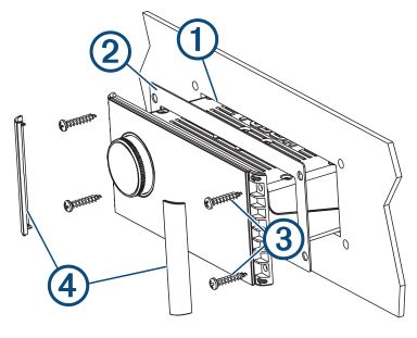
- Cut the mounting surface 1 along the inside of the dashed line on the template.

- Ensure the mounting holes on the stereo line up with the pilot holes on the template.
- Using an appropriately sized drill bit for the mounting surface and screw type, drill the pilot holes.
- Remove the template from the mounting surface.
- Complete an action:
- If you are installing the stereo in a dry location, place the included mounting gasket 2 on the back of the stereo.
- If you are installing the stereo in a location that is exposed to water, apply silicone-based marine sealant on the mounting surface around the cutout.Do not install the included mounting gasket if you applied sealant to the mounting surface. Using sealant and the mounting gasket may reduce water resistance.
- If you will not have access to the back of the stereo after installation, make the necessary wiring connections.
- Secure the stereo to the mounting surface using the included screws 3. You should hand-tighten the screws when securing the stereo to the mounting surface to avoid over tightening them.
- Snap the screw covers in place 4.
Connection Considerations
For the stereo to function correctly, you must connect it to power, to speakers, and to input sources. You should carefully plan the layout of the stereo, speakers, input sources, optional NMEA 2000 network, and optional Fusion PartyBusTM devices or network before making any connections.
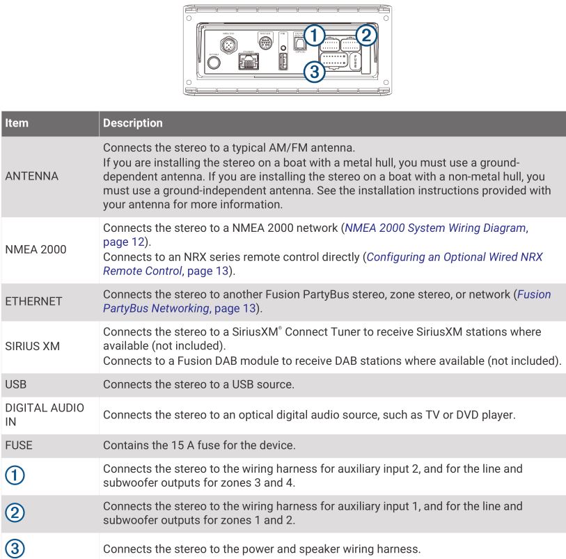
Port Identification
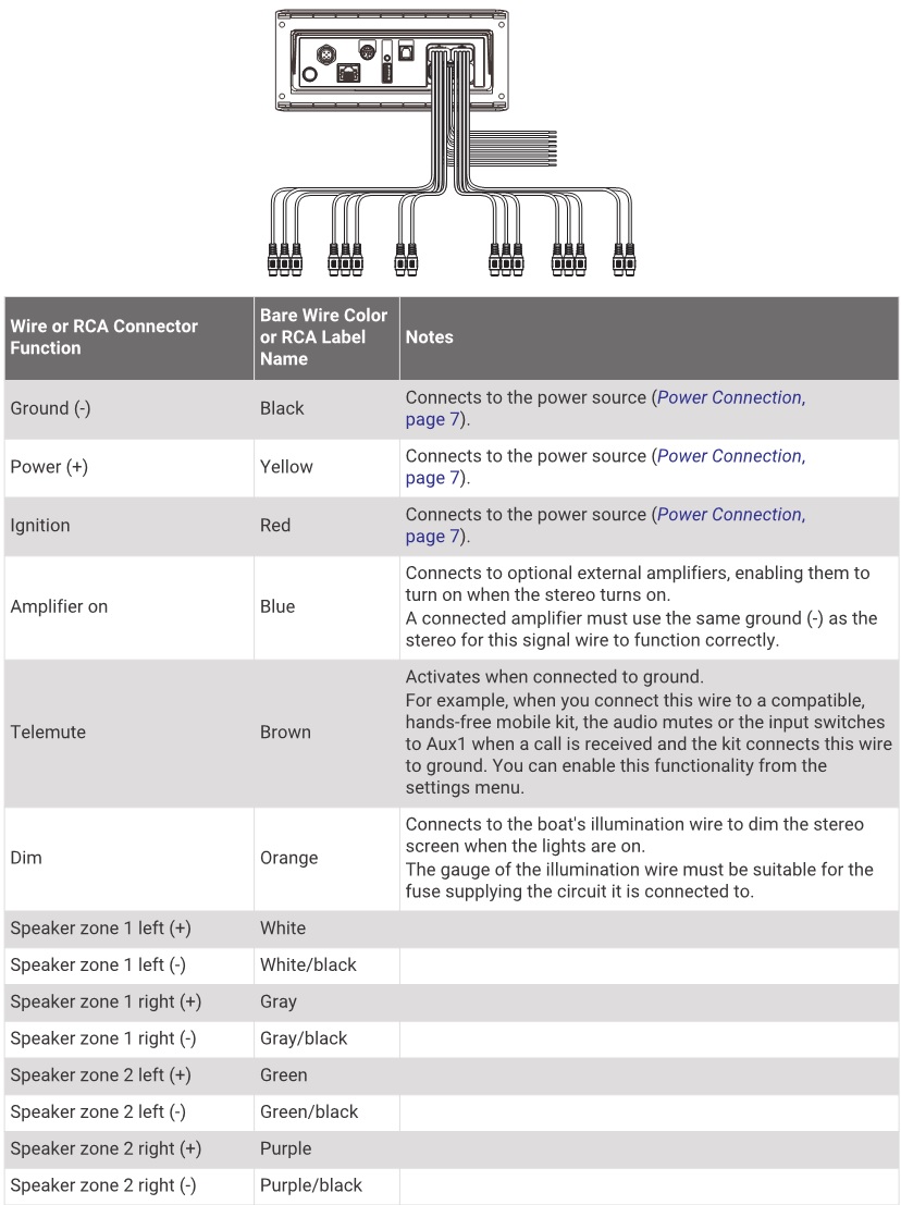
Wiring Harness Wire and Connector Identification
Power Connection
When connecting the stereo to power, you must connect the yellow, red, and black wires to the power source. The yellow and red wires have different functions, and the method you use to connect them to power depends on how you plan to use the stereo on your vessel.
Yellow wire
- This wire provides power to the stereo.
- This wire should be connected through a 15 A circuit breaker, if one is available on the vessel.If a 15 A circuit breaker is not available on the vessel, you must connect this wire to power through a 15 A fuse (not included).
- This wire provides power to the stereo at all times, and it will drain the battery even when the stereo is not in use. You should install a manual switch on this wire if a 15 A circuit breaker is not available on the vessel, or if you cannot toggle the breaker to remove power to the stereo when storing the vessel.
- If it is necessary to extend this wire, use 14 AWG (2.08 mm2) wire. For extensions longer than 1 m (3 ft.), use 12 AWG (3.31 mm²) wire.
Red wire
- This wire can be connected to the same power source as the yellow wire through the ignition or through a manual switch. This enables you to turn the stereo on and off automatically when you turn the vessel on and off, or when you activate the switch.
- Using this wire to turn the stereo on and off behaves in the same way as using the power button on the stereo to turn it on and off. It is not necessary to connect this wire to a switch if you plan to toggle the power using the power button on the stereo or using a connected chartplotter or remote control. This wire must be connected to turn the stereo on.
- When you turn off the stereo using this switch or the power button, it enters a standby mode that allows the stereo to start up again faster than if you switch the power off using the yellow wire. When it is in standby mode, the stereo uses up to 200 mA, and you must turn off power to the stereo on the yellow wire thorough the circuit breaker or manual switch when you are not using the vessel to avoid draining the battery.You must connect this wire to power through a 1 A fuse (not included), whether or not you connect it to the ignition or manual switch.
- If it is necessary to extend this wire, use 22 AWG (0.33 mm2) wire.
Black wire
- This is the ground wire, and you must connect it to the negative terminal of the power source or to a common ground.
- If it is necessary to extend this wire, use 14 AWG (2.08 mm2) wire. For extensions longer than 1 m (3 ft.), use 12 AWG (3.31 mm²) wire.
Connecting to Power Without Using an Ignition Switch
This method of connection is used most often on larger vessels and on vessels with multiple networked stereos and other marine devices. For these installations, a faster startup time is typically less critical, and it is more effective to use the breaker or a dedicated switch on the electrical panel to turn off the stereo and ensure that no unexpected power drain occurs.
- Consult this diagram to plan the wire connections.
- Route all wires to the stereo wiring harness, the circuit breaker or switch, and the power source as necessary.Do not connect the wiring harness to the stereo until after you have made all of the bare wire connections.
- Install all of the necessary fuses on the red and yellow wires.
- Connect the wiring harness to the stereo.
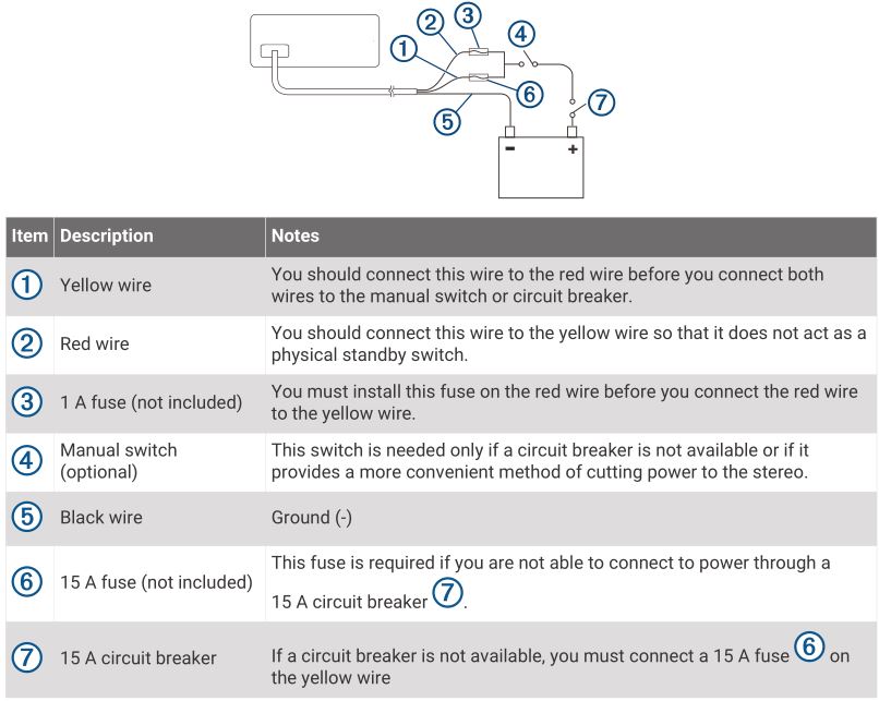
When the circuit breaker or manual switch is closed, the stereo is always on. You can use the power button on the stereo or a connected chartplotter or remote control to place the stereo in a low-power standby mode if needed.
NOTE: When you are not using the vessel, you should remove power to the stereo using the circuit breaker or manual switch to avoid draining the battery.
Connecting to Power Through an Ignition Switch
This method of connection is used most often on ski boats, wake boats, and similar sport or recreational vessels where power to the engines is toggled often. For these installations, a quick standby and faster startup time is desired so that music can be stopped and begin playing again as quickly as possible after restarting the engines. When in standby mode, the stereo uses up to 200 mA, and you should connect the power wires through a circuit breaker or manual switch to avoid draining the battery when you are not using the boat.
- Consult this diagram to plan the wire connections.
- Route all wires to the stereo wiring harness, the ignition or ACC switch, the circuit breaker, and the power source as necessary.Do not connect the wiring harness to the stereo until after you have made all of the bare wire connections.
- Install all of the necessary fuses on the red and yellow wires.
- Connect the wiring harness to the stereo.
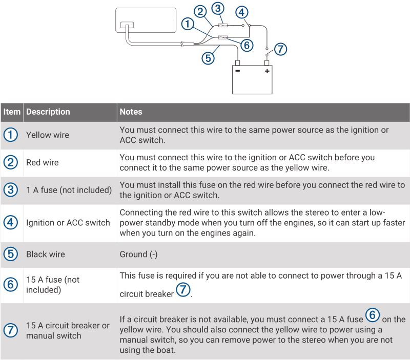
When you turn on the ignition switch, the stereo turns on along with other accessory electronics. When you turn off the ignition switch, the stereo enters a low-power standby mode.
NOTE: When you are not using the vessel for an extended period of time, you should remove power to the stereo using the circuit breaker or other manual switch on the yellow wire to avoid draining the battery.
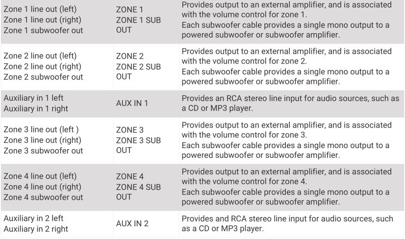
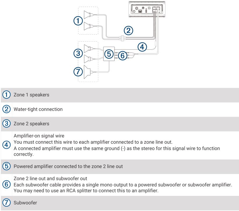
Speaker Zones
You can group speakers in one area into a speaker zone. This enables you to control the audio level of the zones individually. For example, you could make the audio quieter in the cabin and louder on deck. Up to two speakers can be connected per channel (left and right) of each zone, in parallel. A zone can support no more than four speakers using the on-board amplifier. Zones 1 and 2 are powered by the on-board amplifier. To use the RCA line outputs and the RCA subwoofer outputs for zones 1 and 2, you must connect external amplifiers. Zones 3 and 4 are available as line-level outputs only. To use the RCA line outputs and the RCA subwoofer outputs for zones 3 and 4, you must connect external amplifiers. You can set the balance, volume limit, tone, subwoofer frequency, and name for each zone, and configure other zone-specific settings.
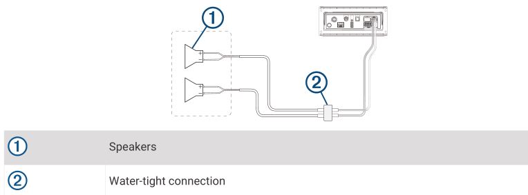
Single-Zone System Wiring Example
Speaker System Wiring Using a Line Out
This diagram illustrates a system installation with an external amplifier and subwoofer connected to zone 2 on the stereo using a line out. You can connect an amplifier and subwoofer to any or all of the available zones on the stereo.
NOTE: You can connect speakers to the speaker wires for the internal stereo amplifier while using the line out on zones 1 and 2, although adjusting the volume affects both the speakers connected to the internal amplifier and the line out. This may result in uneven volume levels.
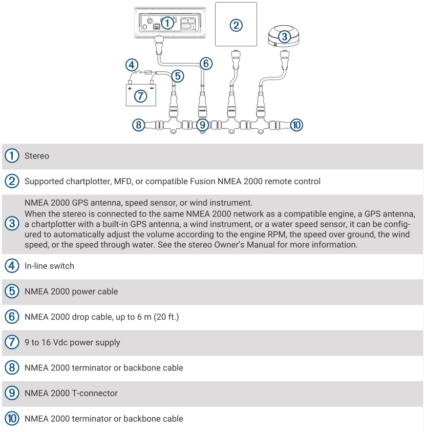
NMEA 2000 System Wiring Diagram
Configuring an Optional Wired NRX Remote Control
![]() The stereo is configured by default to work with a NMEA 2000 network, and the NRX POWER option should be enabled only when an optional wired NRX remote control is connected directly to the stereo. Enabling this option when the stereo is connected to a NMEA 2000 network may damage other devices on the NMEA 2000 network.
The stereo is configured by default to work with a NMEA 2000 network, and the NRX POWER option should be enabled only when an optional wired NRX remote control is connected directly to the stereo. Enabling this option when the stereo is connected to a NMEA 2000 network may damage other devices on the NMEA 2000 network.
If you connect an optional wired NRX remote control directly to the stereo, and not through a NMEA 2000 network, additional configuration is needed.
- Select > SETTINGS > POWER OPTIONS.
- Select an option:
- If you connected both your stereo and your optional wired remote to a NMEA 2000 network, make sure the NRX POWER option is not selected. This enables the optional remote to receive power from the NMEA 2000 network.
- If you connected the optional wired remote directly to the stereo through the NMEA 2000 connector, select the NRX POWER option. This enables the stereo to supply power to the optional remote.
Fusion PartyBus Networking
The Fusion PartyBus networking feature allows you to connect multiple compatible stereos together on a network, using a combination of wired or wireless connections. You can group a compatible stereo, such as the Apollo RA770 stereo, with other compatible stereos connected to the network. Grouped stereos can share available sources and control media playback on all of the stereos in the group, which allows for a synchronized audio experience across the vessel. You can quickly create, edit, and break up groups as needed from any compatible stereo or remote control on the network.
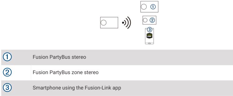
NOTE: A zone stereo, such as the Apollo SRX400, can create or join a group to control and play sources from other stereos, but it cannot share its sources with the group. For additional considerations when sharing sources, see the owner’s manual. You can use compatible stereos and remote controls, whether they are grouped or not, to adjust the volume of the available speaker zones for any stereo on the network. You can connect up to eight Fusion PartyBus stereos on a network wirelessly.
Wired Networking Considerations
When you are planning your network installation, observe the following considerations for all wired connections.
- You must connect devices using standard Cat5e or Cat6 network cables with RJ45 connectors.
- You can use one network cable to directly connect two compatible devices.
- You must use wired network switches and wired or wireless network routers when you connect more than two compatible devices to a network.
- If you install a router on the network, it should be configured to be a DHCP server by default. See your router instructions for more information.
- If you do not install a router, and there are no other DHCP servers on the network, you should configure one Fusion PartyBus stereo to be a DHCP server (Setting the Fusion PartyBus Device as the DHCP Server, page 17).
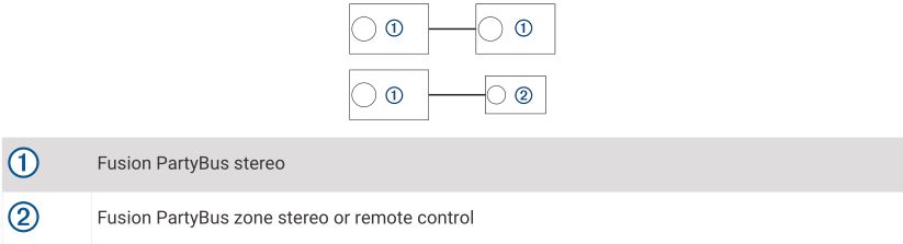
Wired Network Example for Direct Connections
No network setting changes are needed when connecting two devices together directly, but for the best results, you should configure one device to be a DHCP server (Setting the Fusion PartyBus Device as the DHCP Server, page 17).
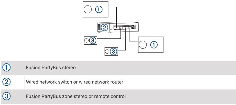
Wired Network Example with a Switch or Router
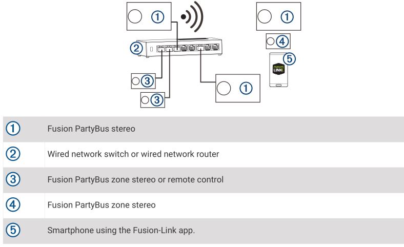
You must use wired network switches, a wired network router, or both to connect more than two devices. If you did not install a router, and there are no other DHCP servers on the network, you should configure one Fusion PartyBus stereo to be a DHCP server (Setting the Fusion PartyBus Device as the DHCP Server, page 17). If you installed a router, you may need to configure it to be a DHCP server. See your router instructions for more information.
Wireless Networking Considerations
When you are planning your network, observe the following considerations for all wireless connections.
- Wired connections are more reliable than wireless connections. You should plan your network to use network cables, but if it is not possible, many Fusion PartyBus devices are WiFi® compatible. You can connect them to wireless routers or access points.
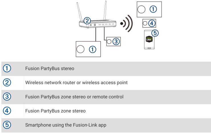
- If you install a wireless router on the network, it should be configured to be the DHCP server by default. See your wireless router instructions for more information.
- If you are not using a wireless router, you can configure this device as a wireless access point, so you can connect other devices within wireless range.NOTE: You should not configure this device as a wireless access point if you have a router installed on the network, because it may introduce DHCP conflicts and result in poor network performance.
- If you connect a Fusion PartyBus device to the network as a WI-FI CLIENT, you cannot connect any additional wired Fusion PartyBus devices to that device.
- You can connect a smartphone to the wireless network to control any stereo on the network using the Fusion-LinkTM app.
- You can connect an Apple® device to the wireless network to stream media to multiple stereos on the network using Apple AirPlay® 2.
- Connecting a Bluetooth® device to the stereo may interfere with some WiFi connections.
- WiFi signals may interfere with Bluetooth device connections. You should turn off the WiFi setting on your stereo if you are not using it to connect to a wireless network or to provide a wireless access point.
Wireless Access Point Example
Wireless Network Example with a Wired Switch or Router
Wireless Network Example with a Wireless Router or Access Point
Constructing a Network
You should have a basic understanding of networking when building a network for Fusion PartyBus devices. These instructions guide you through the basics of building and configuring a network, and should apply to most situations. If you need to perform advanced networking tasks, such as assigning static IP addresses to devices on the network or configuring advanced settings on a connected router, you may need to consult a networking professional.
- Determine the installation location of the Fusion PartyBus devices you want to connect to the network.NOTE: Wired connections are more reliable than wireless connections. When planning your network, you should run network cables instead of using wireless connections when possible.
- Determine the installation location of any needed network routers or switches.
- Route Cat5e or Cat6 network cable to the installation locations of the stereos, switches, and router.
- Connect the network cables to the stereos, switches, and router.Do not completely install the stereos yet. You should test the network before you install the stereos.
- Turn on all devices connected to the network, including wireless devices.
- Select an option:
- If you are using a network router (wired or wireless), consult the documentation provided with your router to configure the router as the DHCP server, if necessary. When using a router as the DHCP server, all stereos on the network should use their default configuration (DHCP client).
- If you are not using a wireless router, you should configure a stereo as a wireless access point, if necessary (Setting the Fusion PartyBus Device as a Wireless Access Point, page 18). Configuring a stereo as a wireless access point makes that stereo the DHCP server, and all of the other stereos on the network should use their default configuration (DHCP client).
- If you are not using a network router, not using a stereo as a wireless access point, and there are no other DHCP servers on the network, you should configure one of the stereos as the DHCP server (Setting the Fusion PartyBus Device as the DHCP Server, page 17).
- Test the network by selecting select an option: > GROUPS to view a list of devices connected to the on the network, and select an option:
- If any Fusion PartyBus devices are not available to the network, troubleshoot the network (Network Troubleshooting, page 19).
- If all Fusion PartyBus devices are available on the network, complete the installation for each stereo, if necessary.
Network Configuration
TIP: You can select the network status icon from any screen to open the network configuration menu.
Setting the Fusion PartyBus Device as the DHCP Server
If you connected more than two network devices together using a network switch or wireless access point but you did not install a router, you should configure only one Fusion PartyBus stereo to be a DHCP server.
![]() Having more than one DHCP server on the network causes instability and poor performance for all devices on the network.
Having more than one DHCP server on the network causes instability and poor performance for all devices on the network.
NOTE: If you have set up this stereo as a WI-FI ACCESS POINT, it is configured as a DHCP server by default, and no further settings changes are needed (Setting the Fusion PartyBus Device as a Wireless Access Point, page 18).
- If the device is connected to the network using an Ethernet cable, select FI OFF. > SETTINGS > NETWORK > WI-FI OFF.
- If the device is connected to the network using an Ethernet cable, select STATIC IP > SAVE.
- Select ADVANCED > DHCP SERVER > DHCP ENABLED > SAVE.
Configuring the Stereo for use with a Garmin® Marine Network
You can connect this stereo to a Garmin Marine Network in order to view and control the stereo using a compatible Garmin chart-plotter.
NOTE: When you configure the stereo for use with a Garmin Marine Network, you are limited to using only Garmin and Fusion devices. You may not be able to use third-party routers, storage devices, or other network products with this stereo directly. When the stereo is connected to a Garmin Marine Network, you can connect a smartphone to a wireless access point on a connected Garmin chart-plotter and use the Fusion-Link app to control the stereo. You cannot use WiFi networking on a stereo configured for use with a Garmin Marine Network. This functionality is compatible with wired network connections only.
Select ![]() > SETTINGS > NETWORK > WI-FI OFF > GARMIN MARINE NETWORK.
> SETTINGS > NETWORK > WI-FI OFF > GARMIN MARINE NETWORK.
Setting the Fusion PartyBus Device as a Wireless Access Point
Before you can connect additional Fusion PartyBus devices or smartphones to a Fusion PartyBus device wirelessly, you must configure one device as a wireless access point. This is not necessary if you installed a wireless router or other wireless access point on the network.
NOTE: You should not configure this device as a wireless access point if you have a router installed on the network. Doing so may introduce DHCP conflicts and result in poor network performance. For more detailed configuration instructions, see the owner’s manual.
- Select > SETTINGS > NETWORK > WI-FI ACCESS POINT.
- Select USE DEFAULTS and wait for the device to save the network settings.NOTE: After the default settings are saved, you can scroll down to the bottom of the NETWORK menu to view and change the SSID and password assigned to the access point.
NOTE: When you configure the stereo as a wireless access point, you can also use the wired network connection without changing any additional settings. The wired and wireless networks are bridged.
Connecting the Fusion PartyBus Device to a Wireless Access Point
You can connect this device to a wireless access point on a router or compatible Fusion PartyBus device on the network. This device can connect using WiFi Protected Setup (WPS), if it is supported by your access point. This device can connect using Apple Accessory Configuration (WAC) using a supported Apple device.
- Select > SETTINGS > NETWORK > WI-FI CLIENT > SSID.A list of wireless access points within rage appears.
- Select the Fusion PartyBus wireless access point.
- If necessary, select PASSWORD, enter the password, and select √.
- Select SAVE.NOTE: When you connect the stereo to a wireless access point, you cannot use the wired network connection.
Resetting Network Settings
You can reset all network settings for this stereo to the factory default values.
- Select > SETTINGS.
- Select NETWORK > ADVANCED > RESET > YES.
Advanced Network Configuration
You can perform advanced networking tasks on a Fusion PartyBus device, such as defining DHCP ranges and setting static IP addresses. See the owner’s manual for more information.
Network Troubleshooting
If you cannot see or connect to Fusion PartyBus devices on the network, check the following:
- Verify that only one device, either a stereo or a router, is configured as a DHCP server.
- Verify that all Fusion PartyBus devices, network switches, routers, and wireless access points are connected to the network and turned on.
- Verify that wireless Fusion PartyBus devices are connected to a wireless router or wireless access point on the network.NOTE: Wired connections are more reliable than wireless connections. If possible, you should connect devices to the network using an Ethernet cable.
- You may experience wireless interference if there are many nearby wireless access points. Change the channel on your router or wireless access point to test for and correct interference.
- Connecting a Bluetooth device to a stereo configured as a wireless access point or client may reduce wireless performance. Disconnect Bluetooth devices to test for and correct interference.
- If you configured static IP addresses, verify that every device has a unique IP address, that the first three sets of numbers in the IP addresses match, and that the subnet masks on every device are identical.
- If you have made configuration changes that might be causing networking issues, reset all network settings to the factory default values.
Stereo Information
Specifications
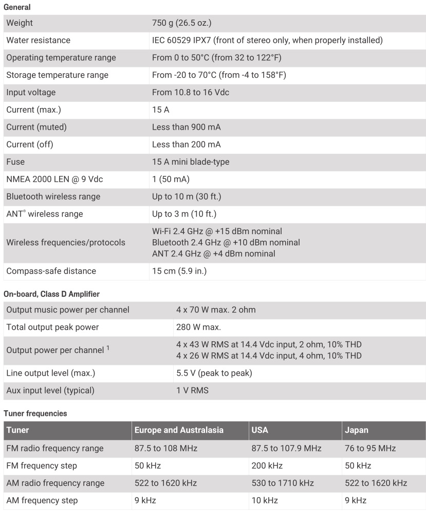
The stereo may limit the output power to prevent the amplifier from overheating, and to maintain the audio dynamics.
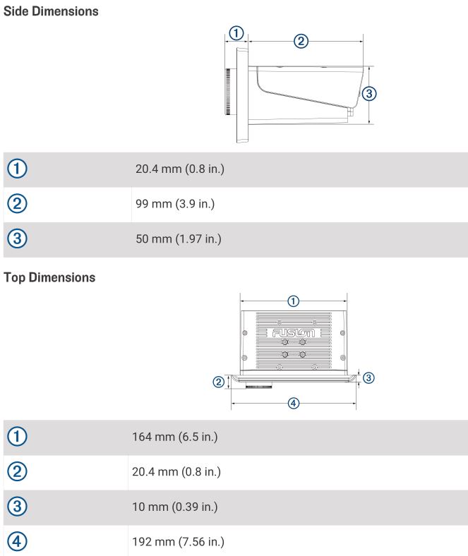
Stereo Dimension Drawings
Software Updates
Go to support.garmin.com to find software updates and information for your device.
© 2018 Garmin Ltd. or its subsidiariessupport.garmin.com
References
[xyz-ips snippet=”download-snippet”]