![]() Fusion® MS-RA60 Installation Instructions
Fusion® MS-RA60 Installation Instructions
Important Safety Information
![]() WARNINGFailure to follow these warnings and cautions could result in personal injury, damage to the vessel, or poor product performance.See the Important Safety and Product Information guide in the product box for product warnings and other important information.This device must be installed according to these instructions.Disconnect the vessel’s power supply before beginning to install this product.Before applying power to this product, make sure it has been correctly grounded, following the instructions in the guide.
WARNINGFailure to follow these warnings and cautions could result in personal injury, damage to the vessel, or poor product performance.See the Important Safety and Product Information guide in the product box for product warnings and other important information.This device must be installed according to these instructions.Disconnect the vessel’s power supply before beginning to install this product.Before applying power to this product, make sure it has been correctly grounded, following the instructions in the guide.
![]() CAUTIONTo avoid possible personal injury, always wear safety goggles, ear protection, and a dust mask when drilling, cutting, or sanding.NOTICEWhen drilling or cutting, always check what is on the opposite side of the surface to avoid damaging the vessel.You must read all installation instructions before beginning the installation. If you experience difficulty during the installation, contact Fusion Product Support.
CAUTIONTo avoid possible personal injury, always wear safety goggles, ear protection, and a dust mask when drilling, cutting, or sanding.NOTICEWhen drilling or cutting, always check what is on the opposite side of the surface to avoid damaging the vessel.You must read all installation instructions before beginning the installation. If you experience difficulty during the installation, contact Fusion Product Support.
What’s In the Box
- Mounting gasket
- Four 6-gauge, self-tapping screws
- Two screw covers
- Power and speaker wiring harness
- Auxiliary-in, line-out, and subwoofer-out wiring harness
Tools Needed
- Phillips screwdriver
- Electric drill
- Drill bit (size varies based on the surface material and screws used)
- Rotary cutting tool or jigsaw
- Silicone-based marine sealant (optional)

Mounting Considerations
- You must mount the stereo on a flat surface that provides open airflow around the rear of the stereo for heat ventilation.
- If you are installing the stereo in a location that may be exposed to water, you must mount it within 45 degrees of the horizontal plane.
- If you are installing the stereo in a location that may be exposed to water, add a drip loop to the cable to allow water to drip off of the cable and avoid damage to the stereo.
- If you need to mount the stereo outside a boat, you must mount it in a location far above the waterline, where it is not submerged, and where it cannot be damaged by docks, pilings, or other pieces of equipment.
- To avoid interference with a magnetic compass, you must install the stereo at least 15 cm (5.9 in.) away from a compass.
Mounting the Stereo
NOTICEDo not use the stereo as a template when drilling the mounting holes because this may damage the display and void the warranty. You must only use the included template to correctly drill the mounting holes.Be careful when cutting the hole to mount the stereo. There is only a small amount of clearance between the case and the mounting holes, and cutting the hole too large could compromise the stability of the stereo after it is mounted.Do not apply grease or lubricant to the screws when fastening the stereo to the mounting surface. Grease or other lubricants can cause damage to the stereo housing.Before you can mount the stereo in a new location on the mounting surface, you must select a location in accordance with the mounting considerations.
- Adhere the template to the mounting surface.
- Drill a hole inside the corner of the dashed line on the template.
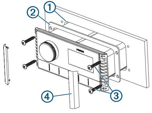
- Cut the mounting surface 1 along the inside of the dashed line on the template.

- Ensure the mounting holes on the stereo line up with the pilot holes on the template.
- Using an appropriately sized drill bit for the mounting surface and screw type, drill the pilot holes.
- Remove the template from the mounting surface.
- Complete an action:• If you are installing the stereo in a dry location, place the included mounting gasket 2 on the back of the stereo.• If you are installing the stereo in a location that is exposed to water, apply silicone-based marine sealant on the mounting surface around the cutout.NOTICEDo not install the included mounting gasket if you applied sealant to the mounting surface. Using sealant and the mounting gasket may reduce water resistance.
- If you will not have access to the back of the stereo after installation, make the necessary wiring connections.
- Secure the stereo to the mounting surface using the included screws.You should hand-tighten the screws when securing the stereo to the mounting surface to avoid over-tightening them 3.
- Snap the screw covers in place 4.
ConnectionsThe stereo must be connected to power, to speakers, and to media input sources to function correctly. You should carefully plan the layout of the stereo, speakers, and your input sources before making any connections.
Port Identification
| Item | Description |
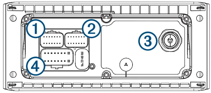
| FUSE | Contains the 15 A fuse for the device. |
| 1 | Not used. |
| 2 | Connects the stereo to the auxiliary in and zone 1 line/subwoofer out the wiring harness. |
| 3 | Connects the stereo to a typical AM/FM antenna using a Motorola-type antenna connector.If you are installing the stereo on a boat with a metal hull, you must use a ground-dependent antenna,and if you are installing the stereo on a boat with a non-metal hull, you must use a ground-independentantenna. See the installation instructions provided with your antenna for more information. |
| 4 | Connects the stereo to the power and speaker wiring harness. |
Wiring Harness Wire and Connector Identification

| Wire Function | Wire Color/Number | Notes |
| Power (+) | Red | Connects to the positive terminal of a 12 Vdc power source capable of supplying 15 A. |
| Ground (-) | Black | Connects to the negative terminal of a 12 Vdc power source capable of supplying 15 A. This wire should be connected before connecting the red wire. All accessories connected to the stereo must share a common ground location. |
| Amplifier on | Blue | Connects to an optional external amplifier to turn it on when the stereo turns on. |
| Dim | Orange | Connects to the boat’s illumination wire to dim the stereo screen when the lights are on.The gauge of the illumination wire must be suitable for the fuse supplying the circuit it is connected to. |
| Speaker zone 1 left (+) | White | |
| Speaker zone 1 left (-) | White/black | |
| Speaker zone 1 right (+) | Gray | |
| Speaker zone 1 right (-) | Gray/black | |
| Speaker zone 2 left (+) | Green | |
| Speaker zone 2 left (-) | Green/black | |
| Speaker zone 2 right (+) | Purple | |
| Speaker zone 2 right (-) | Purple/black | |
| Auxiliary in leftAuxiliary in right | 1 | Provides a red and white RCA stereo line input for audio sources,such as a CD or MP3 player. |
| Zone 1 line out leftZone 1 line outright | 2 | Provides a full-range output to an external amplifier, and is associted with the volume control for zone 1. |
| Subwoofer out | 3 | Provides a single mono output to a powered subwoofer orsubwoofer amplifier.A connected subwoofer is associated with the volume control forzone 1. |
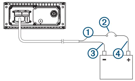
Connecting to PowerWhen connecting the stereo to power, you should connect it through a circuit breaker rated for 15 A.If it is necessary to extend the power and ground wires, use 14 AWG (2.08 mm ) wire. For extensions longer than 1 m (3 ft.), use 12 AWG (3.31 mm 2 ) wire.
- Route the red power wire 2 to a circuit breaker rated for 15 A 2 , and route the black ground wire to 2 the battery.
- If necessary, route a wire between the circuit breaker and the battery .
- Route the wiring-harness plug to the stereo.Do not connect the wiring harness to the stereo until after all of the bare wire connections have been made.
- Connect the black wire to the negative (-) battery terminal.
- Connect the red power wire to the circuit breaker, and connect the circuit breaker to the positive (+) battery terminal.
- Connect the wiring harness plug to the stereo.
Speaker ZonesYou can group speakers in one area into speaker zones. This enables you to control the audio level of the zones individually. For example, you could make the audio quieter in the cabin and louder on deck.One pair of 4 Ohm speakers can be connected per zone.Zones 1 and 2 are powered by the onboard amplifier. To use the RCA line output and the RCA subwoofer output (associated with zone 1), you must connect an external amplifier.You can set the balance, volume limit, tone, and name for each zone. You can set the subwoofer level for zone 1.
Single-Zone System Wiring Example
| 1 | Speakers |
| 2 | Water-tight connection |
Complete System WiringThis diagram illustrates a system installation with an external amplifier and subwoofer connected to the stereo using a line out. You can connect an amplifier and subwoofer only to zone 1 on the stereo.NOTE: You can also connect speakers to the speaker wires for the internal stereo amplifier while using an external amplifier connected to the line out. Adjusting the volume affects speakers connected to the internal amplifier and speakers connected to the line out. This may result in uneven volume levels.
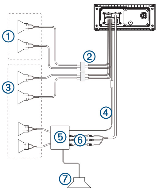
| Item | Description |
| 1 | Zone 2 speakers |
| 2 | Water-tight connection |
| 3 | Zone 1 speakers |
| 4 | Amplifier-on signal wire |
| 5 | Powered amplifier |
| 6 | Zone 1 line out and zone 1 subwoofer out |
| 7 | Zone 1 subwoofer |
Stereo Information
Specifications
| General | |
| Weight | 316g (11.2 oz) |
| Water resistance | IEC 60529 IPX7 (front), IEC 60529 IPX5 (rear)1 |
| Operating temperature range | From 0 to 50°C (from 32 to 122°F) |
| Storage temperature range | From -20 to 70°C (from -4 to 158°F) |
| Input voltage | From 10.8 to 16 Vdc |
| Current (max.) | 15 A |
| Current (muted) | less than 190 mA |
| ANT® wireless range | Up to 3 m (10 ft.) |
| Compass-safe distance | 15 cm (5.9 in.) |
| Fuse | 15 A mini-blade type |
| Bluetooth® wireless range | Up to 10 m (30 ft.) |
| Wireless frequencies/protocols | Bluetooth 2.4 GHz at 12 dBm maximum ANT 2.4 GHz @ 7 dBm maximum |
| On-board, Class D Amplifier | |
| Output power per channel | 4 x 22 W RMS at 14.4 Vdc input, 4 Ohm, 10% THD2 |
| Total output music power | 4 x 45 W max. 4 Ohm. 180 W max. |
| Line output level (max.) | 5.5 V (peak to peak) |
| Aux input level (typical) | 1 V RMS |
| Tuner | Europe and Australasia | USA | Japan |
| FM radio frequency range | 87.5 to 108 MHz | 87.5 to 107.9 MHz | 76 to 95 MHz |
| FM frequency step | 50 kHz | 200 kHz | 50 kHz |
| AM radio frequency range | 522 to 1620 kHz | 530 to 1710 kHz | 522 to 1620 kHz |
| AM frequency step | 9 kHz | 10 kHz | 9 kHz |
1From the front, the device withstands immersion in water of up to 1 m for up to 30 m. From the rear, the device withstands light jets of water (up to 30 kPa (4.4 psi) at a distance of 3 meters) for up to 3 min.2The stereo may limit the output power to prevent the amplifier from overheating and to maintain the audio dynamics.
Stereo Dimension Drawings
Front Dimensions
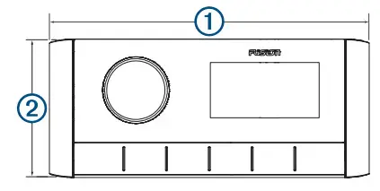
| 1 | 157 mm (6³ /16in.) |
| 2 | 68 mm (2¹¹ /16in.) |
Side Dimensions
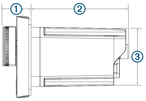
| 1 | 22 mm (7 /8in.) |
| 2 | 81.2 mm ( 3 /16 in.) |
| 3 | 50 mm (2 in.) |
Top Dimensions
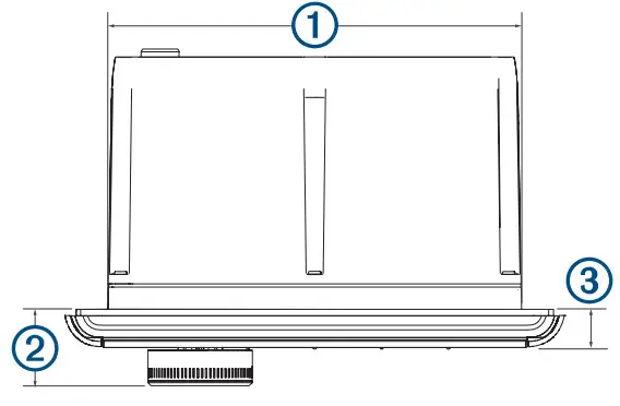
| 1 | 130 mm (5¹ /8 in.) |
| 2 | 22 mm (7 /8 in.) |
| 3 | 10 mm (3 /8 in.) |
Registering Your Fusion DeviceHelp us better support you by completing our online registration today.
- Go to www.fusionentertainment.com.
- Keep the original sales receipt, or a photocopy, in a safe place.
Software UpdatesFor best results, you should update the software in all Fusion devices at the time of installation to ensure compatibility.You can update the software using the Fusion-Link™ remote control app on your compatible Apple® or Android™ device. To download the app and update the device software, go to the Apple App StoreSM or the Google Play ™ store.© 2021 Garmin Ltd. or its subsidiaries Garmin®, the Garmin logo, ANT®, Fusion®, and the Fusion logo are trademarks of Garmin Ltd. or its subsidiaries, registered in the USA and other countries. Connect IQ™ ,Fusion-Link™ and Fusion-Link Lite™ are trademarks of Garmin Ltd. or its subsidiaries. These trademarks may not be used without the express permission of Garmin.Apple®, the Apple logo, iPod touch ®, and iPhone® is a service mark of Apple Inc., registered in the USA and other countries. Android are trademarks of Apple Inc., registered in the U.S. and other countries. App StoreSM ™ and Google Play™ are trademarks of Google Inc. The trademark iPhone® is used in Japan with a license from Aiphone K.K. Bluetooth® word mark and logos are owned by the Bluetooth SIG, Inc. and any use of such marks by Garmin is under license. Other trademarks and trade names are those of their respective owners.A03942
© 2021 Garmin Ltd. or its subsidiaries
References
[xyz-ips snippet=”download-snippet”]