
![]() SG-DA61500/SG-24DA61500 SignatureSeries Amplifier InstallationInstructions
SG-DA61500/SG-24DA61500 SignatureSeries Amplifier InstallationInstructions
Important Safety Information
![]() WARNINGSee the Important Safety and Product Information guide in the product box for product warnings and other important information.This device must be installed according to these instructions.Disconnect the vehicle’s or vessel’s power supply before beginning to install this device.
WARNINGSee the Important Safety and Product Information guide in the product box for product warnings and other important information.This device must be installed according to these instructions.Disconnect the vehicle’s or vessel’s power supply before beginning to install this device.![]() CAUTIONTo maintain ignition protection compliance in accordance with SAE J1171, you must replace the fuse only with a J1171 compliant fuse.Continuous exposure to sound pressure levels over 100 dBA may cause permanent hearing loss. The volume is typically too loud if you cannot hear people speaking around you. Limit the amount of time you listen at a high volume. If you experience ringing in your ears or muffled speech, stop listening and have your hearing checked.Always wear safety goggles, ear protection, and a dust mask when drilling, cutting, or sanding.NOTICEWhen drilling or cutting, always check what is on the opposite side of the surface.The SG-DA61500 device is designed for a 12 Vdc power source. The SG-24DA61500 device is designed for a 24 Vdc power source. Connecting to a larger power source may damage the device.It is strongly recommended that you have your audio system installed by a professional installer to ensure optimum performance.You must read all installation instructions before beginning the installation. If you experience difficulty during the installation, go to www.fusionentertainment.com for product support.
CAUTIONTo maintain ignition protection compliance in accordance with SAE J1171, you must replace the fuse only with a J1171 compliant fuse.Continuous exposure to sound pressure levels over 100 dBA may cause permanent hearing loss. The volume is typically too loud if you cannot hear people speaking around you. Limit the amount of time you listen at a high volume. If you experience ringing in your ears or muffled speech, stop listening and have your hearing checked.Always wear safety goggles, ear protection, and a dust mask when drilling, cutting, or sanding.NOTICEWhen drilling or cutting, always check what is on the opposite side of the surface.The SG-DA61500 device is designed for a 12 Vdc power source. The SG-24DA61500 device is designed for a 24 Vdc power source. Connecting to a larger power source may damage the device.It is strongly recommended that you have your audio system installed by a professional installer to ensure optimum performance.You must read all installation instructions before beginning the installation. If you experience difficulty during the installation, go to www.fusionentertainment.com for product support.
Tools Needed
- Drill and drill bits
- Flat screwdriver
- Wirecutter
- Wire stripper
- 120 A inline fuse or circuit breaker for 12-volt models or 60 A inline fuse or circuit breaker for 24-volt models
- 4 AWG (21.1 mm² ) power cableNOTE: You may need thicker cable for higher amperages or longer runs (Power Cable Gauge Guide, page 2).
- 16 AWG (1.31 mm ²) speaker wireNOTE: You may need thicker wire for longer runs (Speaker Wire Gauge Guide, page 3).
- 20 AWG (0.52 mm ²) wire (amplifier turn-on signal)
- Dual RCA cable (1 per zone, for stereo speakers) (Signal and Speaker Connection Considerations, page 3)
- Single RCA cable and RCA splitter (1 per zone, for mono subwoofer or bridged output for speakers) (Signal and Speaker Connection Considerations, page 3)
- Cable ties (optional)
Mounting Considerations
![]() CAUTIONIn high ambient temperatures and after extended use, the device enclosure may reach temperatures deemed dangerous to touch. Therefore the device must be installed in a location where it will not be touched during operation.NOTICEThis device should be mounted in a location that is not exposed to extreme temperatures or conditions. The temperature range for this device is listed in the product specifications. Extended exposure to temperatures exceeding the specified temperature range, in storage or operating conditions, may cause device failure. Extreme-temperature-induced damage and related consequences are not covered by the warranty.This device is designed for installation only in a dry location. Installing this device in a location where it may come in contact with water or become submerged may result in damage. Water damage is not covered by the warranty.
CAUTIONIn high ambient temperatures and after extended use, the device enclosure may reach temperatures deemed dangerous to touch. Therefore the device must be installed in a location where it will not be touched during operation.NOTICEThis device should be mounted in a location that is not exposed to extreme temperatures or conditions. The temperature range for this device is listed in the product specifications. Extended exposure to temperatures exceeding the specified temperature range, in storage or operating conditions, may cause device failure. Extreme-temperature-induced damage and related consequences are not covered by the warranty.This device is designed for installation only in a dry location. Installing this device in a location where it may come in contact with water or become submerged may result in damage. Water damage is not covered by the warranty.
- The device must be mounted in a location that does not interfere with the fuel tank or electrical wiring.
- The device must be mounted in a location where it is not exposed to water.
- The device must be mounted in a location with adequate ventilation where it is not exposed to extreme temperatures.
- If the device is mounted in an enclosed space, you should install a cooling fan with appropriate ducts to aid in airflow.
- The device should be mounted so that the cables can be connected easily.
- To avoid interference with a magnetic compass, the device should be installed at least 55 cm (22 in.) away from a compass.
- The device should not be mounted in close proximity to other navigation-critical equipment, antennas, or radiocommunication equipment on thevessel.
Mounting the SG-DA61500/SG-24DA61500 Signature Series DeviceNOTICEIf you are mounting the device in fiberglass, when drilling the pilot holes, it is recommended to use a countersink bit to drill a clearance counterbore through only the top gel-coat layer. This will help to avoid cracking in the gel-coat layer when the screws are tightened.NOTE: Screws are included with the device, but they may not be suitable for the mounting surface.Before you mount the device, you must select a mounting location and determine what screws and other mounting hardware are needed for the surface.
- Place the device in the mounting location and mark the location of the pilot holes.
- Drill a pilot hole for one corner of the device.
- Loosely fasten the device to the mounting surface with one corner and examine the other three pilot-hole marks.
- Mark new pilot-hole locations if necessary, and remove the device from the mounting surface.
- Drill the remaining pilot holes.
- Secure the device to the mounting location.
Removing the CoverYou must remove the cover to reach the connectors and configuration controls on the amplifier.
- Using the included 3 mm hex key, remove the screws that secure the cover to the amplifier.
- Lift the cover off of the amplifier and set it aside until after you have finished making all of the connections and configured the amplifier.
Connection ConsiderationsNOTICEThe wiring (not included) from the battery to the amplifier must run through an inline fuse or circuit breaker (not included) as close to the battery as possible. You must connect the positive wire to the fuse or circuit breaker. Connecting the amplifier to power without an inline fuse or circuit breaker may result in a fire if there is a short in the cable.You must turn off the audio system before making any connections to the amplifier. Failure to turn off the audio system may result in damage to the audio system.All terminals and connections must be protected from contact with the vessel chassis and with each other. Improper terminal or wire contact may result in damage to the audio system.
- You must first connect the amplifier to the ground before making any other wiring connections (Connecting to Power, page 2).
- You must connect the positive wire to the battery only after you have completed all other wirings to the amplifier.
- If your stereo does not have a remote turn-on signal wire, you must connect the amplifier to a switched power source.
Port Identification
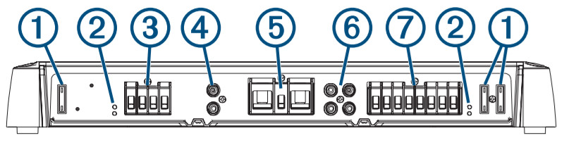
| 1 | Fuses. See the product specifications for replacement details. |
| 2 | POWER and PROT (protection) LED indicators (Troubleshooting, page 5) |
| 3 | Zone 1 speaker terminals |
| 4 | Zone 1 RCA input |
| 5 | Power, ground, and amplifier turn-on terminals |
| 6 | Zones 2 and 3 RCA inputs |
| 7 | Zones 2 and 3 speaker terminals |
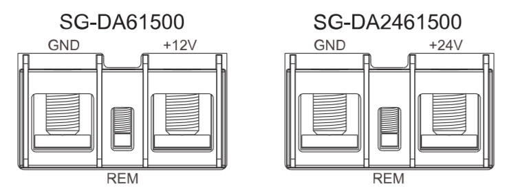
Connecting to PowerYou must connect the power wire to the battery through an inline fuse or a circuit breaker.You must use the appropriate gauge of wire (not included) to connect the amplifier to power and ground, based on the total amperage and the length of the cable run (Power Cable Gauge Guide, page 2).
- Route the appropriate gauge of wire to the amplifier and to a ground location on the boat.
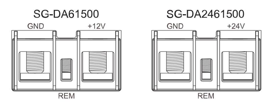
- Using the included 3 mm hex key, connect the ground wire to the GND terminal on the amplifier.

- Connect the other end of the ground wire to the ground location on the boat.
- Route the appropriate gauge of wire to the amplifier and to the boat battery, and select an option:• Install a properly rated in-line fuse on the power wire as close to the battery as possible.• Identify or install a circuit breaker, as close to the battery as possible, for use with the amplifier power wire.NOTICEYou must not connect the power wire to the amplifier and battery or circuit breaker before you complete all of the other connections. Connecting the amplifier to power before you complete all of the other connections may cause damage to your audio system.
- Select an option:• If your stereo has an amplifier turn-on wire, route a 20 AWG (0.52 mm ²) wire from the amplifier turn-on wire on the stereo to the amplifier.NOTE: The amplifier and the stereo must connect to the same physical ground location for the amplifier turn-on signal to function properly.• If your stereo does not have an amplifier turn-on wire, route a 20 AWG (0.52 mm ) wire from the positive terminal of the battery, through a switch, to the amplifier.
- Using the included 2.5 mm hex key, connect the 20 AWG (0.52 mm 2 ) wire to the REM terminal on the amplifier.
Make all of the other connections to the stereo and speakers before completing the connection to power (Completing the Connections, page 4).
Power Cable Gauge GuideYou should use 4 AWG (21.1 mm² ) wires for most installations. If your total amperage is higher than 50–65 A, and your cable run is longer than 10–13 ft (3–4 m), you can use these tables to determine if you need to use a larger gauge of wire. This table accounts for terminal connection resistance.NOTE: If you are using aluminum wire, you should use a wire two gauges larger than the gauge listed below to compensate for a potential voltage drop due to the wire material.
| Total Amperage | 0-4 ft. (0-1.2 m) | 4-7 ft. (1.2-2.1 m) | 7-10 ft. (2.1-3 m) | 10-13 ft. (3-4 m) |
| 85-105A | 4AWG (21.1 mm2) | 4AWG (21.1 mm2) | 4AWG (21.1 mm2) | 2AWG (33.6 mm2) |
| 105-125 A | 4 AWG (21.1 mm2) | 4 AWG (21.1 mm2) | 4 AWG (21.1 mm2) | 2 AWG (33.6 mm2) |
| 125-150 A | 2 AWG (33.6 mm2) | 2 AWG (33.6 mm2) | 2 AWG (33.6 mm2) | 0 AWG (53.5 mm2) |
| Total Amperage | 13-16 ft. (4-4.9 m) | 16-19 ft.(4.9-5.8 m) | 19-22 ft. (5.8-6.7 m) | 22-28 ft. (6.7-8.5 m) |
| 50-65A | 4AWG (21.1 mm2) | 4AWG (21.1 mm2) | 4AWG (21.1 mm2) | 2AWG (33.6 mm2) |
| 65-85A | 2AWG (33.6 mm2) | 2AWG (33.6 mm2) | 2AWG (33.6 mm2) | OAWG (53.5 mm2) |
| 85-105A | 2AWG (33.6 mm2) | 2AWG (33.6 mm2) | 2AWG (33.6 mm2) | OAWG (53.5 mm2) |
| 105–125 A | 0 AWG (53.5 mm2) | 0 AWG (53.5 mm2) | 0 AWG (53.5 mm2) | 0 AWG (53.5 mm2) |
| 125–150 A | 0 AWG (53.5 mm2) | 0 AWG (53.5 mm2) | 0 AWG (53.5 mm2) | 0 AWG (53.5 mm2) |
Signal and Speaker Connection ConsiderationsWhen connecting your stereo and speakers to the amplifier, observe the following considerations:
- Each set of zone speaker terminals on the amplifier is paired to the RCA inputs for that zone.
- Each channel supports a nominal 4 Ohm speaker load impedance and a 2 Ohm minimum speaker load impedance.
- You can connect two speakers in parallel on a single channel, and the combined impedance must be greater than the 2 Ohm minimum load impedance (Connecting Multiple Speakers or Subwoofers In Parallel, page 3).
- You can connect either a zone line out or a subwoofer line out from the stereo to any of the zone RCA inputs on the amplifier.
- You should use the proper gauge speaker wire noted in the Speaker Wire Gauge Guide, page 3 to connect speakers and subwoofers to the amplifier.
- You should observe the zone and polarity markings for each channel when connecting speakers to the amplifier. For example, Z1L indicates the ZONE 1 left channel, and Z1R indicates the ZONE 1 right channel.
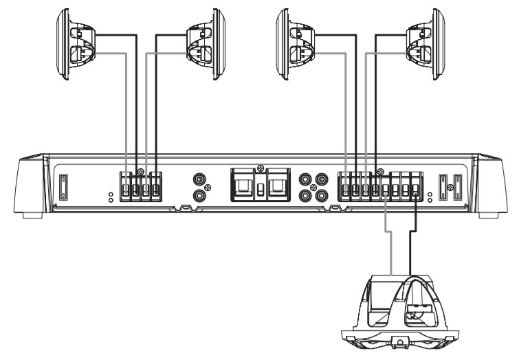
- If you are connecting a combination of speakers and a subwoofer to the amplifier, you should connect the subwoofer to ZONE 3 as illustrated below. This zone has a dedicated BASS BOOST control.
- You can connect a subwoofer to a single channel, but you should connect it using bridge mode to get the best performance (Connecting a Speaker or Subwoofer in Bridge Mode, page 3).
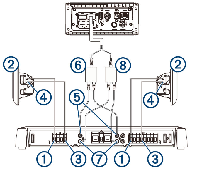
In the following example, a single 4 Ohm subwoofer is connected to the bridged terminals for ZONE 3, and pairs of 4 Ohm speakers are connected to the right and left channels for the other two zones.In this example, you must connect the subwoofer line out from the stereo to the Z3L and Z3R RCA connectors on the amplifier (using an RCA splitter), you must connect the two-zone line out connectors from the stereo to the other two zones RCA connectors on the amplifier.
Speaker Wire Gauge GuideYou should use 16 AWG (1.31 mm2) speaker wires for most installations. You can use this table to determine if you need to use a larger gauge of wire. This table accounts for terminal connection resistance.NOTE: If you are using aluminum or tinned wire, you should use a wire two gauges larger than the gauge listed below to compensate for a potential voltage drop due to the wire material.
4 Ohm Load (1 Speaker)
| Distance between the amplifier and speaker | Wire gauge | Recommended cable |
| From 0 to 28 ft. (from 0 to 8.5 m) | 16 AWG (1.31 mm² ) | 010-12899-00¹ |
| From 28 to 69 ft. (from 8.5 to 21 m) | 12 AWG (3.31 mm²) | 010-12898-00 |
2 Ohm Load (2 Speakers in Parallel)
| Distance between the amplifier and speaker | Wire gauge | Recommended cable |
| From 0 to 14 ft. (from 0 to 4 m) | 16 AWG (1.31 mm² ) | 010-12899-00 |
| From 14 to 35 ft. (from 4 to 10.5 m) | 12 AWG (3.31 mm²) | 010-12898-00 |
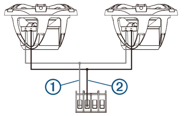
Connecting Multiple Speakers or Subwoofers In ParallelYou can connect multiple speakers or subwoofers with the same impedance rating, model number, and type them together in parallel.When connecting speakers of the same impedance rating in parallel, you must calculate the total impedance by dividing the common impedance rating by the total number of speakers connected in parallel. For example, if you connect two 4 Ohm speakers in parallel, the resulting impedance is 2 Ohm (4 ÷ 2= 2).NOTICEYou must not connect a series of speakers with an impedance less than 2 Ohm to a single channel on the amplifier. Do not connect more than two speakers in parallel per zone output.
- Connect the speaker wire to 1 the positive terminal for channel or zone on the amplifier.
- Connect the speaker wire to the positive terminal on each speaker.
- Connect the wires from the positive terminals on both speakers in the channel or zone to the wire connected to the positive terminal on the amplifier.
- Repeat this procedure for the negative terminal on amplifier 2 and both speakers in the channel or zone.
Connecting a Speaker or Subwoofer in Bridge ModeConnecting a speaker or subwoofer in bridge mode increases the amount of power that can be delivered by combining two output channels together. This is beneficial for large subwoofers that move large volumes of air and for playing speakers louder without experiencing clipping in the audio.NOTICEA speaker connected in bridge mode must be capable of handling the increased output power. Bridge mode can produce more than double the output power of a single channel.You should connect only a 4 Ohm load to the bridged terminals on a zone. Connecting a 2 Ohm load to the bridged terminals may cause damage to the amplifier, speaker, or subwoofer.¹Fusion speaker cable is sold in various lengths. See your FUSION® dealer for more information.
NOTE: When bridging the channels in a zone, you must use an RCA splitter to send the same signal to both the left and right channels of the zone.
- Connect the speaker wire to the amplifier’s positive terminal of the left channel for zone 1.
- Connect the other end of the speaker wire to the positive terminal on the speaker or subwoofer 2.NOTE: The bridged terminals for a zone are connected with a line and labeled BRIDGED for easy identification.
- Connect the speaker wire to the negative terminal of the right channel for zone 3.
- Connect the other end of the speaker wire to the negative terminal on the speaker or subwoofer 4.
- Connect the split ends of an RCA splitter to the left RCA ports for both bridged zones on amplifier 5.
- Connect the single end of the RCA splitter to the left RCA stereo output 6.
- Connect the split ends of an RCA splitter to the right RCA ports for both bridged zones on amplifier 7.
- Connect the single end of the RCA splitter to the right RCA stereo output 8.
- Adjust the volume level and other settings for the zone (Adjusting the Level for a Zone, page 4).
Completing the ConnectionsBefore you connect the amplifier to the power source, you must complete all other connections to the amplifier.
- Make sure all speaker wires are connected to the speakers and the amplifier.
- Make sure all RCA cables are connected to the amplifier and the stereo.
- Make sure the ground cable is connected to the amplifier and the battery (Connecting to Power, page 2).
- Make sure the amplifier turn-on wire is connected to the amplifier and to the amplifier turn-on wire from the stereo or a dedicated switch (Connecting to Power, page 2).
- Using the included 3 mm hex key, connect the power wire to the positive terminal on the amplifier.NOTICEThe SG-DA61500 device is designed for a 12 Vdc power source. The SG-24DA61500 device is designed for a 24 Vdc power source. Connecting to the incorrect power source may damage the device.
- Select an option:• Connect the other end of the power wire, through the inline fuse, to the battery.•Connect the other end of the power wire to the appropriate circuit breaker.
Configuring the AmplifierBefore you use the amplifier, you should configure it for any connected speakers and subwoofers.You must make all power, speaker, and stereo connections before you can configure the amplifier.NOTE: If your stereo features digital signal processing (DSP), such as a FUSION Apollo™ RA770, you should use the FUSION-Link™ app when configuring the amplifier (Configuring the Amplifier for a DSP Compatible Stereo, page 5).Amplifier Configuration Controls
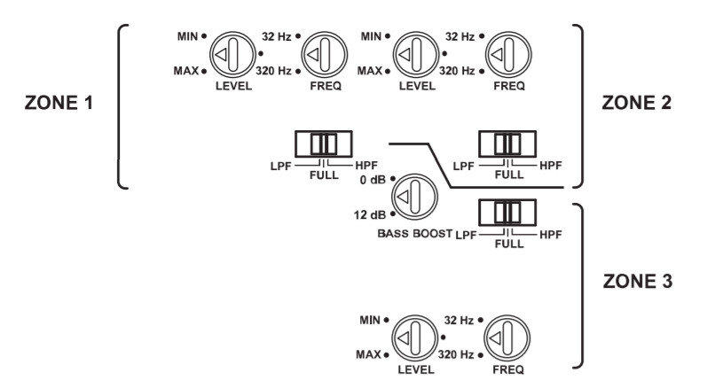
Each zone has a set of controls you must use to configure the sound for the speakers connected to that zone.
|
Dial or Switch |
Function |
| LEVEL | Adjusts the input signal level for the zone (Adjusting the Level for a Zone, page 4). |
| FULL | Sets a full-range filter on the zone.Allows all frequencies. This is usually used when full-range speakers are connected to the zone, and no subwoofer is present. |
| LPF | Sets a low-pass filter on the zone.Filters out mid to high frequencies that only full-range speakers should produce. This is usually used when a subwoofer is connected to the zone. |
| HPF | Sets a high-pass filter on the zone.Filters out low frequencies that only subwoofers should produce. This is usually used when smaller speakers are connected to the zone. |
| FREQ | Adjusts the crossover frequency for the zoneYou should adjust this based on the LPF/HPF setting:
|
| BASS BOOST | Adjusts the gain on the 45 Hz level.This control is available on ZONE 3 only.This setting should be adjusted only when you connect a subwoofer or full-range speakers capable of low frequencies to the zone. |
Adjusting the Level for a ZoneNOTE: The level set is music-dependent, and not all levels are appropriate for all types of music. For example, if you adjust the level setting for rock music, then listen to classical music, it could result in distortion due to clipping.
- Using a flat screwdriver, adjust the LEVEL dial for the zone to MIN by turning the dial counter-clockwise.
- Begin playing audio on the stereo and set the zone line out to approximately 3/4 volume.
- Slowly adjust the LEVEL dial for the zone clockwise toward the MAX setting while listening to the speakers connected to that zone.
- When the sound from the speakers becomes distorted, stop adjusting the dial, and slowly adjust the dial counterclockwise again until the distortion is gone.
- Repeat this procedure for the other zones.
Configuring the Amplifier for a DSP Compatible StereoIf your stereo features digital signal processing (DSP), such as a FUSION Apollo RA770, you should use the FUSION-Link app when configuring the amplifier for the best results.
- Follow the instructions in your stereo owner’s manual to download the FUSION-Link app and connect it to the stereo.
- Select the appropriate stereo, amplifier, and speakers in the FUSION-Link app.
- Follow the instructions in the FUSION-Link app to adjust the configuration controls on the amplifier.
Specifications
12V Models
| VRated power output | 4 Ohm: 100 W RMS x 6 @ 14.4 Vdc input < 1%THD+N (EIA/CEA-490A)2 Ohm: 140 W RMS x 6 @ 14.4 Vdc input < 1%THD+N (EIA/CEA-490A)4 Ohm bridged: 280 W RMS x 3 @ 14.4 Vdc input < 1%THD+N (EIA/CEA-490A) |
| Input sensitivity | 0.3 Vdc to 8 Vdc RMS, adjustable |
| Operating voltage | 10.8 to 16 Vdc |
| Current draw (@14.4 Vdc input) | Standby: less than 1 mAIdle: less than 2.5 AMax: 75 A |
| Fuse rating | 3 @ 40 A ATC blade-type (SAE J1171 compliant)NOTICETo maintain ignition protection compliance in accordance with SAE J1171, replace only with J1171 fuses, such as a Bussmann ATC-40. Using non-compliant fuses may damage the amplifier and voids your warranty. |
| 24V Models | |
| Rated power output | 4 Ohm: 100 W RMS x 6 @ 28.8 Vdc input < 1%THD+N (EIA/CEA-490A)2 Ohm: 140 W RMS x 6 @ 28.8 Vdc input < 1%THD+N (EIA/CEA-490A)4 Ohm bridged: 280 W RMS x 3 @ 28.8 Vdc input <1% THD+N (EIA/CEA-490A) |
| Input sensitivity | 0.3 Vdc to 6 Vdc RMS, adjustable |
| Operating voltage | 21.6 to 32 Vdc |
| Current draw (@28.8 Vdc input) | Standby: less than 1 mAIdle: less than 1.25 AMax: 35 A |
| Fuse rating | 3 @ 20 A ATC blade-type (SAE J1171 compliant)NOTICE To maintain ignition protection compliance in accordance with SAE J1171, replace only with J1171 fuses. Using non-compliant fuses may damage the amplifier and voids your warranty. |
All Models
| Amplifier class | Class D |
| Frequency response | 10 Hz to 40 kHz (-3 dB @ 4 Ohm rated power) |
| Peak power output | 1500 W |
| Input impedance | 7 kOhm nominal |
| Signal to noise ratio | 85 dB @ rated power output, 4 Ohm 53.1 dB @ 1 W, 4 Ohm |
| Separation/crosstalk | 60 dB |
| High-pass/low-pass filter | User-selectable |
| Filter crossover frequency | 32 Hz to 320 Hz, user-adjustable |
| Filter crossover slope | 12 dB/octave |
| Bass boost | 0 to 9 dB, user-adjustable (ZONE 3 only) |
| Remote turn-on | 6 Vdc threshold |
| Protection circuits | Reverse voltageInput under/over voltage Over temperatureOutput short circuit |
| Compass-safe distance | 55 cm (22 in.) |
| Operating temperature range | From 0 to 50°C (from 32 to 122°F) |
| Storage temperature range | From -20 to 70°C (from -4 to 158°F) |
| Water rating | Must be installed in a dry location |
| Weight | 4.5 kg (9.9 lb) with the cover installed |
Dimensions
|
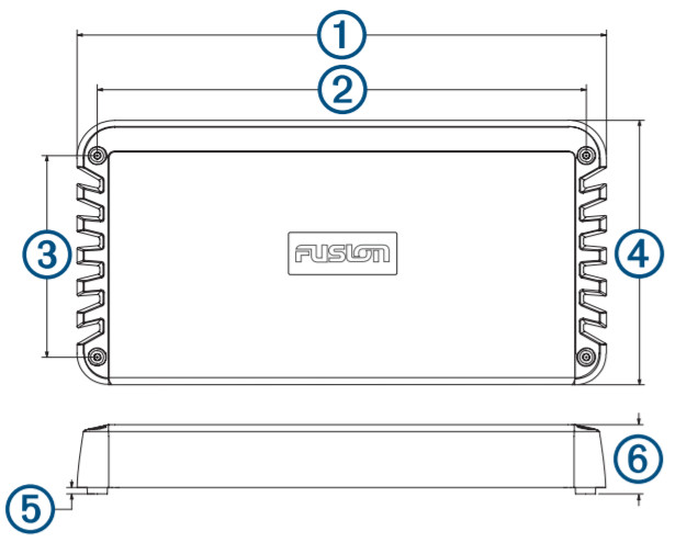
1 |
420 mm (16 9/16 in.) |
|
2 |
388 mm (15 1/4 in.) |
|
3 |
160 mm (6 5/16 in.) |
|
4 |
210 mm (8 9/32 in.) |
|
5 |
5 mm (3/16 in.) |
|
6 |
56.6 mm (2 1/4 in.) |
More Information
Registering Your SG-DA61500/SG-24DA61500 Signature SeriesHelp us better support you by registering the product online.
- Go to www.fusionentertainment.com.
- Keep the sales receipt, or a copy, in a safe place.
TroubleshootingBefore you contact your FUSION dealer or service center, you should perform a few simple troubleshooting steps to help diagnose the problem.If the FUSION amplifier has been installed by a professional installation company, you should contact the company so a technician can assess the problem and advise you about possible solutions.
There is no sound, and the POWER LEDs are off
- Check the amplifier turn-on wire connection to the stereo or switch, and tighten or reconnect all wires, if needed (Connecting to Power, page 2).NOTE: The amplifier and the stereo must connect to a common ground for the amplifier turn-on signal to function properly.
- Check the fuse or circuit breaker on the power cable (near the battery), and replace the fuse or reset the breaker, if needed.
- Check the fuses on the amplifier, and replace all blown fuses, if needed. If a fuse has blown, the red PROT LED will be on.
- Check the power and ground cable connections, and tighten or reconnect all cables, if needed.
- Make sure the power is connected correctly according to the wiring diagram and directions.
- Make sure the supply voltage is the proper voltage for your amplifier.
- Make sure you are using the appropriate gauge for the length of the power cable run, and replace the cable with a thicker gauge if needed (Power Cable Gauge Guide, page 2).
There is no sound, and the POWER LEDs are on
- Check the settings on the stereo, and make sure the appropriate zone out or subwoofer out signals are enabled.NOTE: See your stereo owner’s manual for more information on enabling or configuring output signals.
- Make sure the stereo is powered on and the volume is not set too low.
- Check the RCA cable connections to the stereo, and reconnect all disconnected cables, if needed.
- Check the LEVEL setting for the zone on the amplifier and the max volume setting for the zone on the stereo, and increase the LEVEL on the amplifier or the max volume on the stereo, if needed (Adjusting the Level for a Zone, page 4).
- Check the speaker wire connections, and re-connect all disconnected wires, if needed.
- Check the power cables to make sure they are the appropriate gauge, are fused, and are connected properly (Connecting to Power, page 2).
One POWER LED is on, but the other POWER LED is off
- Check the fuses on the side of the amplifier where the POWER LED is off, and replace all blown fuses.
The PROT LEDs are onThe PROT LEDs indicate a fault in the system. When a fault is detected, the amplifier shuts down to prevent damage.
- Check the power and ground cables for cuts in the sleeving or bare wire contact, and correct, repair, or replace the cables if necessary.
- Check the speaker wires for cuts in the sleeving or bare wire contact, and correct, repair, or replace the cables if necessary.
- Check the temperature of the amplifier, and if the amplifier is very hot, move it to an area with better ventilation or install a ventilation fan (Mounting Considerations, page 1).
There is a hum or other unexpected noise from a speaker
- Install ground-loop isolators in line with the RCA cables from the stereo.NOTE: You should install ground-loop isolators on all RCA cables connected to the stereo.You should install ground-loop isolators on the RCA cables where they connect to the stereo, not where they connect to the amplifier.
The sound is distorted or clipping
- Check the output from the stereo, and adjust the zone line out to approximately 3/4 volumes if needed.
- Adjust the LEVEL setting on the amplifier for the zone or zones experiencing distortion or clipping until the issue is corrected.NOTE: The level set depends upon the type of music and not all levels are appropriate for all types of music. For example, if you adjust the level setting for rock music, then listen to classical music, you could experience distortion due to clipping.
![]() www.fusionentertainment.com© 2019 Garmin Ltd. or its subsidiariesGUID-E1123DA0-B5C3-4C9E-84E7-41E2D7952C89 v3July 2020
www.fusionentertainment.com© 2019 Garmin Ltd. or its subsidiariesGUID-E1123DA0-B5C3-4C9E-84E7-41E2D7952C89 v3July 2020
![]()
References
[xyz-ips snippet=”download-snippet”]