![]()
INSTALLATION INSTRUCTIONS
Important Safety Information
![]() WARNINGFailure to follow these warnings, cautions, and notices could result in personal injury, damage to the vessel or device, or poor product performance.See the Important Safety and Product Information guide in the product box for product warnings and other important information.When connecting the power cable, do not remove the in-line fuse holder. To prevent the possibility of injury or product damage caused by fire or overheating, the appropriate fuse must be in place as indicated in the product specifications. In addition, connecting the power cable without the appropriate fuse in place voids the product warranty.
WARNINGFailure to follow these warnings, cautions, and notices could result in personal injury, damage to the vessel or device, or poor product performance.See the Important Safety and Product Information guide in the product box for product warnings and other important information.When connecting the power cable, do not remove the in-line fuse holder. To prevent the possibility of injury or product damage caused by fire or overheating, the appropriate fuse must be in place as indicated in the product specifications. In addition, connecting the power cable without the appropriate fuse in place voids the product warranty.
![]() CAUTIONTo avoid possible personal injury, always wear safety goggles, ear protection, and a dust mask when drilling, cutting, or sanding.To avoid possible personal injury or damage to the device and vessel, disconnect the vessel’s power supply before beginning to install the device.To avoid possible personal injury or damage to the device or vessel, before applying power to the device, make sure that it has been properly grounded, following the instructions in the guide.
CAUTIONTo avoid possible personal injury, always wear safety goggles, ear protection, and a dust mask when drilling, cutting, or sanding.To avoid possible personal injury or damage to the device and vessel, disconnect the vessel’s power supply before beginning to install the device.To avoid possible personal injury or damage to the device or vessel, before applying power to the device, make sure that it has been properly grounded, following the instructions in the guide.
NOTICEFor the best possible performance, the device must be installed according to these instructions.When drilling or cutting, always check what is on the opposite side of the surface to avoid damaging the vessel.Read all installation instructions before proceeding with the installation. If you experience difficulty during the installation, contact Garmin® Product Support.
Contacting Garmin Support
- Go to support.garmin.com for help and information, such as product manuals, frequently asked questions, videos, and customer support.
- In the USA, call 913-397-8200 or 1-800-800-1020.
- In the UK, call 0808 238 0000.
- In Europe, call +44 (0) 870 850 1241.
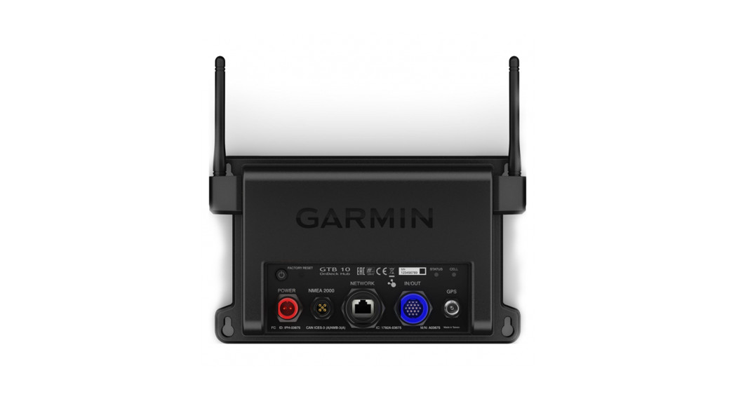
Connector View
| Power button | |
| FACTORY RESET | Deletes all personal data and resets default settings |
| STATUS | Indicates device status |
| CELL | Indicates cell operation |
| POWER | Power cable connection |
| NMEA 2000 | NMEA 2000′ network |
| NETWORK | Garmin Marine Network |
| IN/OUT | Connects relays and wired sensors, such as temperature, security, and shore power |
| GPS | Connects to an external GPS antenna |
Tools Needed
- Drill
- Drill bits appropriate for the surface and hardware
- Phillips screwdrivers
- Pencil
- olderless wire-splice connector, or solder and heat-shrink tubing
Mounting Considerations
NOTICEThis device should be mounted in a location that is not exposed to extreme temperatures or conditions. The temperature range for this device is listed in the product specifications. Extended exposure to temperatures exceeding the specified temperature range, in storage or operating conditions, may cause device failure. Extreme-temperature-induced damage and related consequences are not covered by the warranty.
- You must mount the device in a location where it will not be submerged.
- You must mount the device in a location with adequate ventilation where it will not be exposed to extreme temperatures.
- You must mount the device at least 102 mm (4 in.) from cables and other potential sources of interference.
- You must mount the device in a location that allows room for the routing and connection of all cables.
- You must mount the device with the connectors facing up when mounted on a horizontal surface or out when mounted on a vertical surface. Do not install with the connectors facing down or facing the mounting surface. The internal GPS antenna will not work if mounted in this orientation. See Installing the Antennas, page 2.
- For optimal internal GPS reception, you should mount the device in a location where it is above the water line when the vessel is in the water and if possible, has a clear view of the sky.
- If you mount the device in a vessel with a metal hull or with the internal GPS antenna blocked or oriented poorly, you must connect the device to an external GPS antenna (sold separately).
- For the best cellular signal, mount the device where it has a clear view of the sky. If it is mounted inside of a cabin, it should be close to a window so it can receive the cellular signal.
Mounting the GTB 10 Black Box Device
NOTICEIf you are mounting the device in fiberglass, when drilling the pilot holes, use a countersink bit to drill a clearance counterbore through only the top gel-coat layer. This will help to avoid cracking in the gel-coat layer when the screws are tightened.
NOTE: Screws are included with the device, but they may not be suitable for the mounting surface.Before you mount the device, you must select a mounting location, and determine what screws and other mounting hardware are needed for the surface.
- Place the black box device in the mounting location, and mark the location of the pilot holes.
- Drill a pilot hole for one corner of the device.
- Loosely fasten the device to the mounting surface with one corner, and examine the other three pilot-hole marks.
- Mark new pilot-hole locations if necessary, and remove the device from the mounting surface.
- Drill the remaining pilot holes.
- Secure the device to the mounting location.
Installing the AntennasAfter mounting the device, you must orient both antennas pointing toward the sky for the best reception.
- Remove the black, rubber cap from the connector.
- Loosely attach the antenna to the connector.
- Orient the antenna toward the sky.• If you are installing the device on a vertical surface, such as a bulkhead, you must install the antennas parallel to the black box .• If you are installing the device on a horizontal surface, you must install the antennas perpendicular to the black box .NOTE: You must have the antenna oriented properly for the cover to fit.

- While holding the antenna in the appropriate position, finger tighten the antenna nut.
- Using the included wrench, rotate the nut another 45 degrees to fully tighten the antenna nut.The recommended torque applied to the nut is 0.56 N-m (5 lbf-in.), or finger tight plus 45 degrees.NOTICETo ensure a water-tight connection, tighten the antenna nut to 0.56 N-m (5 lbf-in.). Over tightening the nut could cause damage to the device.
- Place the cover over the connecter.
- Secure the cover using the small screw and included #0 Phillips screwdriver.
- Repeat these steps to install the second antenna.
Connection Considerations
When connecting this device to power and to other Garmin devices, you should observe these considerations.
- You must check the power and ground connections to the battery to make sure they are secured and cannot become loose.
- You must make sure the locking rings are tightened so the power or data connection remains secure.
- Bare wire connections must be water tight if they will be exposed to moisture. You can use heat-shrink type butt connectors or other water-tight connections.
- To prevent corrosion of the metal contacts, you must cover unused connectors with weather caps.
- For the best connection of the GPS antenna, completely remove the weather cap from the GPS connector.
- If you need to extend the IN/OUT wires, use minimum of 24 AWG (0.08 mm2) wire.
- You should install a 1 Amp fuse on all relay controls, Boat-inUse, Bilge 1/2, and Battery 1/2 input wires at the positive input to the power source.
Connecting to Power
![]() WARNINGWhen connecting the power cable, do not remove the in-line fuse holder. To prevent the possibility of injury or product damage caused by fire or overheating, the appropriate fuse must be in place as indicated in the product specifications. In addition, connecting the power cable without the appropriate fuse in place voids the product warranty.To properly monitor your vessel when the ignition is off, you should not connect the power cable to the device through the ignition.
WARNINGWhen connecting the power cable, do not remove the in-line fuse holder. To prevent the possibility of injury or product damage caused by fire or overheating, the appropriate fuse must be in place as indicated in the product specifications. In addition, connecting the power cable without the appropriate fuse in place voids the product warranty.To properly monitor your vessel when the ignition is off, you should not connect the power cable to the device through the ignition.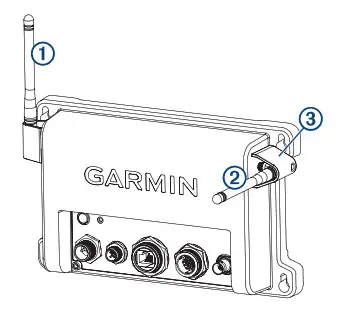
| 1 | Fuse (7.5 A, 42 V fast-acting) |
| 2 | Battery |
| 3 | 6 ft. (1.8 m) no extension |
- Route the power cable between the power source and the device.
- Connect the red power wire to the positive (+) battery terminal.
- Connect the black wire to the negative (-) battery terminal.
- Connect the power cable to the device, and turn the locking ring clockwise to tighten it.
Power Cable ExtensionsIf necessary, the power cable can be extended using the appropriate wire gauge for the length of the extension.
| 1 | Splice |
| 2 | • Up to 15 ft. (4.6 m): 10 AWG (5.26 mm) extension wire• Up to 23 ft. (7 m): 8 AWG (8.36 mm2) extension wire• Up to 36 ft. (11 m): 6 AWG (13.29 mm2) extension wire2 |
| 3 | Fuse (7.5 A, 42 V fast-acting) |
| 4 | 8 in. (20.3 cm) |
| 5 | Battery |
| 6 | 8 in. (20.3 cm) |
| 7 | 36 ft. (11 m) maximum extension |
Connection Diagram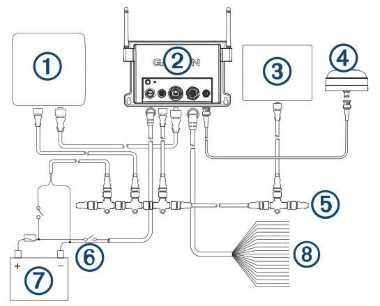
| 1 | Garmin chartplotter connected to the Garmin Marine Network and NMEA 2000 network |
| 2 | GTB 10 black box device |
| 3 | Sensor connected through the NMEA 2000 network |
| 4 | GPS antenna with a BNC connector (sold separately and required only if the internal GPS antenna reception is poor) |
| 5 | NMEA 2000 network |
| 6 | Optional switch. Must be turned on for remote operation |
| 7 | Power source |
| 8 | OnDeck sensors and relays |
IN/OUT Cable Pinout
| Pin Number | Wire Function | Wire Color |
| 1 | Relay 1 | White |
| 2 | Relay 2 | White/orange |
| 3 | Relay 3 | Gray |
| 4 | Relay 4 | Pink |
| 5 | Relay 5 | Brown |
| 6 | Relay 6 (Aux)1 | White/brown |
| 7 | Relay 7 (NMEA 2000) 2 | Blue |
| 8 | Shore Power | White/blue |
| 9 | Wake (unused) | Violet |
| 10 | Boat-in-Use | White/violet |
| 11 | Bilge 1 | White/black |
- This relay is automatically controlled by the GTB 10 black box device to switch power to Garmin Marine Network devices.
- This relay is automatically controlled by the GTB 10 black box device to switch power to NMEA 2000 devices.
| Pin Number | Wire Function | Wire Color |
| 12 | Bilge 2 | Red/white |
| 13 | Security | White/green |
| 14 | Battery 1 Pos | Red |
| 15 | Battery 1 Neg | Green |
| 16 | Battery 2 Pos | Yellow |
| 17 | Battery 2 Neg | Orange |
| 18 | Ground (shield) | Black |
| 19 | Temp | Light green |
NOTICEAll connections should be made using proper electrical connectors. Extra caution must be made when making watertight electrical connections.Notes
- Each relay control wire is rated for up to 1 A. External relay switches are recommended. For higher-current loads, external relay switches are required. Do not connect these wires to the positive side of a power source.
- You should install a 1 Amp fuse on all relay controls, Boat-inUse, Bilge 1/2, and Battery 1/2 inputs at the positive input to the power source.
- The Boat-in-Use, Bilge 1/2, and Battery 1/2 inputs require a voltage between 10 and 32 Vdc.
- If the boat’s ground is ever intended to be switched off from the power source, do not directly connect the Ground (black) wire from the IN/OUT wiring harness to the negative side of the of the GTB 10 black box device’s power source.
Installing the Shore Power SensorYou can connect the AC shore power sensor to the OnDeck system to be alerted when the outlet loses power. The shore power sensor also enables the device to stay in a full-power state when the boat is connected to shore power.
NOTICETo avoid damage to the sensor, you must install this sensor in a dry location.
- Select and install the proper plug type for your AC system. NOTE: Do not plug in the shore power sensor to the power outlet at this time.
- Connect the white wire from the shore power sensor to the white/blue wire on the IN/OUT wiring harness.
- Connect the black wire from the shore power sensor to the black wire on the IN/OUT wiring harness.
- Plug in the shore power sensor to an AC outlet that is connected to the boat’s shore power connection.
Installing the Temperature Sensor
- Connect one wire from the temperature sensor to the light green wire on the IN/OUT wiring harness.
- Connect the other wire from the temperature sensor to the black wire on the IN/OUT wiring harness.
- Use the ring on the temperature sensor to secure it, as needed.You must set up the sensor in the ActiveCaptain® app.
Installing the Security SensorYou can connect up to 30 security sensors carefully installed and tested in series.The two parts of the security sensor should not be more than 10 mm (0.4 in.) apart when the door or window is closed to engage the magnet.
- Select a location on the window or door frame and the window or door that allows the two parts of the sensor to align.
- Use two screws to mount the wired half of the sensor to the door or window frame.
- Use two screws to mount the other half of the sensor to the door or window, ensuring that the two parts align when the door or window is closed.
- Connect one wire from the sensor to the white/green wire on the IN/OUT wiring harness.
- Connect the other wire to the black wire on the IN/OUT wiring harness.You must set up the sensor in the ActiveCaptain app.
Installing a Relay SwitchYou can use an external relay switch to turn on and off an item, such as a light, on your vessel remotely, using the ActiveCaptain app. One 12 V relay is included. If you need more relays or 24 V relays, they are available separately for purchase at garmin.com.
NOTICETo avoid potential damage to the relay switch, GTB 10 black box device, and device being switched, you must install this relay switch in a dry location.
- Connect the correctly colored wire on the IN/OUT wiring harness to the negative control (white) wire on the relay. See IN/OUT Cable Pinout, page 3.NOTE: Do not connect these wires to the positive side of a power source.
- Connect the positive control (black) wire on the relay to a 1 Amp fuse and the positive side of the same power source as the GTB 10 black box device.NOTE: Even though the relay switch and the GTB 10 device have different power ratings, the inputs must be connected to the same power source.
- Connect the positive wire from the power cable for the item to be controlled to the negative load (blue) wire on the relay.
- Connect the positive load (yellow) wire on the relay to the positive terminal of the item’s power source.NOTE: The wire used in step 4 should be the same or greater gauge wire to what was used in step 3.NOTE: You must follow the output power ratings listed in the specifications for the relay type being used.
- Complete the installation of the item to be controlled by connecting the negative wire from the item to the negative side of the power source.You must set up the relay switches in the ActiveCaptain app.
Relay Connection Diagram
NOTICETo avoid potential damage to the relay switch, GTB 10 black box device, and device being switched, you must install this relay switch in a dry location.
| 1 | GTB 10 black box device |
| 2 | GTB 10 black box power cable |
| 3 | GTB 10 IN/OUT cable, corresponding relay wire |
| 4 | Optional switch. Must be turned on for remote operation |
| 5 | Relay (one 12 V relay included) |
| 6 | Power source |
| 7 | Device controlled by the relay, such as a light |
| 1 | Negative control wire, white |
| 2 | Positive control wire, black |
| 3 | Negative load wire, blue |
| 4 | Positive load wire, yellow |
Connecting the Boat-in-Use InputThe Boat-in-Use input enables the device to stay in a full-power state when the boat’s electronics are turned on. If you need to extend the IN/OUT wires, use minimum of 24 AWG (0.08 mm2) wire.
NOTICEYou must connect the Boat-in-Use input so that it receives power when you turn on your Garmin marine devices, including Garmin chartplotters. If you do not connect the Boat-in-Use input, the device may not remain in a full-power state like other Garmin devices, which prevents you from connecting the device to the vessel WiFi® network and updating the software from a connected Garmin chartplotter.
- Connect the white/violet (Boat-in-Use) wire from the IN/OUT wiring harness to a 1 Amp fuse and the positive side of the 10 to 32 Vdc switched boat/accessories power.
- Connect the black wire (Ground) from the IN/OUT wiring harness to the negative side of the source from stepNOTE: If the boat’s ground is ever intended to be switched off from the power source, do not directly connect the Ground (black) wire from the IN/OUT wiring harness to the negative side of the of the GTB 10 black box device’s power source.
Connecting the Battery InputsIf you need to extend the IN/OUT wires, use minimum of 24 AWG (0.08 mm2) wire.
- Connect the Battery 1 Pos (red) or Battery 2 Pos (yellow) wire from the IN/OUT wiring harness to a 1 Amp fuse and the positive side of the boat’s 10 to 32 Vdc battery.
- Connect the corresponding Battery 1 Neg (green) or Battery 2 Neg (orange) wire from the IN/OUT wiring harness to the negative side of the boat’s battery.
To monitor the 10 to 32 Vdc power input to the GTB 10 black box device, you must also connect it to one set of the Battery 1 or Battery 2 inputs.
Connecting the Bilge Pump InputsIf you need to extend the IN/OUT wires, use minimum of 24 AWG (0.08 mm2) wire.
- Connect the Bilge 1 (white/black) or Bilge 2 (red/white) wire from the IN/OUT wiring harness to a 1 Amp fuse and the switched positive side of the bilge pump’s 10 to 32 Vdc power source.NOTE: If you are connecting to an auto-sensing bilge pump with an optional manual connection, you may be able to connect this input to the pump’s manual connection if it is energized to 10 to 32 Vdc when the pump is active.
- Connect the negative side of the bilge pump’s power to the negative side of the power source for the GTB 10 black box device’s power source.NOTE: If the boat’s ground is ever intended to be switched off from the power source, do not directly connect the Ground (black) wire from the IN/OUT wiring harness to the negative side of the of the GTB 10 black box device’s power source.
Garmin Marine Network Considerations
NOTICEA Garmin Marine Network PoE Isolation Coupler (010-10580-10) must be used when connecting any third-party device, such as a FLIR® camera, to a Garmin Marine Network. Connecting a Power over Ethernet (PoE) device directly to a Garmin Marine Network chartplotter damages the Garmin chartplotter and may damage the PoE device. Connecting any third-party device directly to a Garmin Marine Network chartplotter will cause abnormal behavior on the Garmin devices, including the devices not properly turning off or the software becoming inoperable.
This device can connect to additional Garmin Marine Network devices to share data and update the software from a connected Garmin chartplotter. When connecting Garmin Marine Network devices to this device, observe these considerations.
- You must use a Garmin Marine Network cable for all Garmin Marine Network connections.
- You should not use third-party CAT5 cable and RJ45 connectors for Garmin Marine Network connections.
- You can purchase additional Garmin Marine Network cables and connectors from your Garmin dealer or garmin.com.
Garmin Marine Network Connection Diagram with Relay
NOTICETo avoid potential damage to the relay switch, GTB 10 black box device, and device being switched, you must install this relay switch in a dry location.This relay is automatically controlled by the GTB 10 black box device to switch power to Garmin Marine Network devices.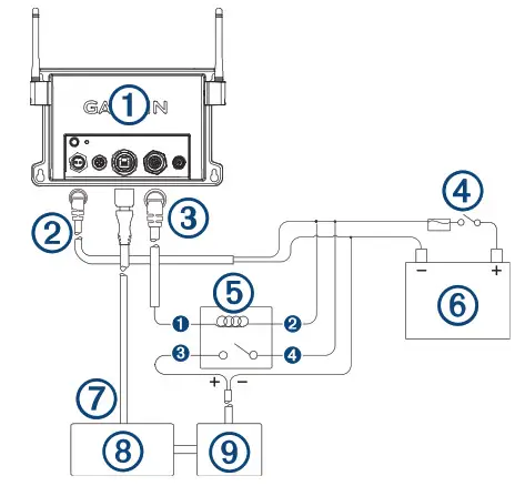
| 1 | GTB 10 black box device |
| 2 | GTB 10 black box power cable |
| 3 | GTB 10 IN/OUT cable, Relay 6 (Aux), white/brown wire |
| 4 | Optional switch. Must be turned on for remote operation |
| 5 | Auxiliary relay (one 12 V relay included) |
| 6 | Power source |
| 7 | Garmin Marine Network cable |
| 8 | GMS 10 network port expander (requires a power connection) |
| 9 | Network device (for future use) |
| 1 | Negative control wire, white |
| 2 | Positive control wire, black |
| 3 | Negative load wire, blue |
| 4 | Positive load wire, yellow |
NMEA 2000 Considerations
NOTICEIf you are connecting to an existing NMEA 2000 network, identify the NMEA 2000 power cable. Only one NMEA 2000 power cable is required for the NMEA 2000 network to operate properly. A NMEA 2000 Power Isolator (010-11580-00) should be used in installations where the existing NMEA 2000 network manufacturer is unknown.
NOTE:If you are installing a NMEA 2000 power cable, you must connect it to a relay, the boat ignition switch, or through another in-line switch. NMEA 2000 devices will drain your battery if the NMEA 2000 power cable is connected to the battery directly. This device can connect to a NMEA 2000 network on your boat to monitor and control compatible NMEA 2000 devices. The included NMEA 2000 cable and connector allow you to connect the device to your existing NMEA 2000 network. If you do not have an existing NMEA 2000 network you can create a basic one using cables from Garmin. If you will only be monitoring part of your NMEA 2000 network remotely with the OnDeck system, you must connect a power isolator to separate the part of the network you will monitor. If you are unfamiliar with NMEA 2000, you should read the “NMEA 2000 Network Fundamentals” chapter of the Technical Reference for NMEA 2000 Products at garmin.com/manuals /nmea_2000.
The port labeled NMEA 2000 is used to connect the device to a standard NMEA 2000 network.
| 1 | GTB 10 black box device |
| 2 | NMEA 2000 compatible Garmin device |
| 3 | Ignition or in-line switch |
| 4 | NMEA 2000 power cable |
| 5 | NMEA 2000 drop cable |
| 6 | Power source |
| 7 | NMEA 2000 terminator or backbone cable |
| 8 | NMEA 2000 T-connector |
| 9 | NMEA 2000 terminator or backbone cable |
NMEA 2000 Connection Diagram with Relay
NOTICETo avoid potential damage to the relay switch, GTB 10 black box device, and device being switched, you must install this relay switch in a dry location.This relay is automatically controlled by the GTB 10 black box device to switch power to NMEA 2000 devices.
| 1 | GTB 10 black box device |
| 2 | GTB 10 black box power cable |
| 3 | GTB 10 IN/OUT cable, Relay 7 (NMEA 2000), blue wire |
| 4 | Optional switch. Must be turned on for remote operation |
| 5 | NMEA 2000 power relay (one 12 V relay included) |
| 6 | Power source |
| 7 | NMEA 2000 device, affected by the relay |
| 8 | NMEA 2000 power cable, for the side of the network not affected by the relay |
| 9 | NMEA 2000 device, not affected by the relay |
| 10 | NMEA 2000 drop cable |
| 11 | NMEA 2000 power cable, connected to the relay |
| 12 | NMEA 2000 power isolator |
| 1 | Negative control wire, white |
| 2 | Positive control wire, black |
| 3 | Negative load wire, blue |
| 4 | Positive load wire, yellow |
GTB 10 Specifications
| Weight | 0.64 kg (1.4 lb.) |
| Compass-safe distance | 102 mm (4 in.) |
| Operating temperature range | From -15° to 55°C (from 5° to 131°F) |
| Internal battery charging temperature range | From 0° to 45°C (from 32° to 113°F) |
| Material | Polycarbonate plastic |
| Water rating | IEC 60529 IPX7 1 |
| Fuse | 7.5 A, 42 V fast-acting |
| Input voltage | From 10 to 32 Vdc |
| Max. power usage @ 10 Vdc | 20 W |
| Typical current draw @ 13.2 Vdc | 40 mA avg. (cycling standby/fullpower state)210 mA avg. (full-power state) |
| Typical current draw in off state | Up to 7 mA avg. |
| Max. current draw @ 13.2 Vdc | 1.5 A |
| NMEA 2000 LEN @ 9 Vdc | 2 |
| NMEA 2000 draw | 75 mA max. |
| Backup battery life | 48 hours (typical use) |
Shore Power Sensor Specifications
| Operating temperature range | From -50° to 105°C (from -58° to 221°F) |
Security Sensor Specifications
| Operating temperature range | From-15° to 80°C (from 5° to 176°F) |
12 V Relay Switch Specifications
| Operating temperature range | From -15° to 85°C (from 5° to 185°F) |
| Storage temperature range | From -40° to 155°C (from -40° to 311°F) |
| Control voltage (coil) | 7.8 to 15.6 Vdc |
| Load power min. (contacts) | 0.1 A |
| Load power max. (contacts) | Up to 15 A at 10 to 16 VdcUp to 9 A at 20 to 32 Vdc |
1 The device withstands incidental exposure to water of up to 1 m for up to 30 min.For more information, go to www.garmin.com/waterrating.
Device Dimensions
| 1. Antennas parallel to the mounting surface | 215.226 mm (8.47 in.) |
| 2. Antenna cover to antenna cover | 230.72 mm (9.08 in.) |
| 3. Antennas perpendicular to the mounting surface | 132.15 mm (5.20 in.) |
| 4. Device only, not including antennas | 141.54 mm (5.57 in.) |
| 5. Device only, not including antennas | 48.89 mm (1.92 in.) |
Wireless Protocols and Frequencies
| Protocol | Frequency range | Typical power |
| UMTS low | 824 to 915 Mhz | -6.4 dBm |
| UMTS mid | 1710 to 1980 Mhz | 20.8 dBm |
| LTE FDD low 1 | 699 to 787 Mhz | 21.8 dBm |
| LTE FDD low 2 | 814 to 862 Mhz | 24.1 dBm |
| LTE FDD low 3 | 880 to 915 Mhz | 20.4 dBm |
| LTE FDD mid 1 | 1710 to 1785 Mhz | 25.1 dBm |
| LTE FDD mid 2 | 1850 to 1980 Mhz | 22.9 dBm |
| LTE FDD high | 2500 to 2570 Mhz | 18.2 dBm |
| LTE FDD high 1 | 1880 to 2400 Mhz | 20.4 dBm |
| LTE FDD high 2 | 2555 to 2655 Mhz | 25.5 dBm |
| ANTWVi-Fi | 2400 to 2480 Mhz | 16.8 dBm |
Status LED
| LED Activity | Status |
| Solid red | The device is turning on. |
| Flashing green | The device is on and operating normally. |
| Flashing orange | The device software is being updated. |
| Flashing red | The device has encountered an error and must be reset by holding the |
| Off | The device is off or in standby mode. |
NMEA 2000 PGN InformationTransmit and Receive
| PGN | Description |
| 59392 | ISO acknowledgment |
| 59904 | ISO request |
| 60160 | ISO transport protocol: Data transfer |
| 60416 | ISO transport protocol: Connection management |
| 60928 | ISO address claim |
| 126208 | Request group function |
| 126993 | Heartbeat |
| 126996 | Product information |
Transmit
| PGN | Description |
| 126464 | Transmit and receive PGN list group function |
| 126998 | Configuration information |
| 126992 | System time |
| 127250 | Vessel heading |
| 127489 | Engine parameters, dynamic |
| 127505 | Fluid level |
| 127508 | Battery status |
| 128259 | Water speed |
| 128267 | Water depth |
| 129025 | Position: Rapid update |
| 129026 | COG and SOG: Rapid update |
| 129029 | GNSS position data |
| 129539 | GNSS DOPs |
| 129540 | GNSS satellites in view |
| 130306 | Wind data |
| 130310 | Environmental parameters (obsolete) |
| 130311 | Environmental parameters (obsolete) |
| 130312 | Temperature (obsolete) |
| 130316 | Temperature: Extended range |
| 130578 | Vessel speed components |
Radio Frequency Radiation ExposureThis device is a mobile transmitter and receiver that uses internal and/or external antenna(s) to send and receive low levels of radio frequency (RF) energy for data communications. The device emits RF energy below the published exposure limits when operating in its maximum output power mode and when used with Garmin authorized accessories. To comply with RF exposure compliance requirements, the device should be installed and operated with a minimum of 20 cm (7.87 in.) between the device and your body. The device should not be used in other configurations. This device must not be co-located or operated in conjunction with any other transmitter or antenna.
Innovation, Science and Economic Development Canada Radio Transmitter ComplianceThis radio transmitter, 1792A-03675, has been approved by Innovation, Science and Economic Development Canada to operate only with the antennas provided by Garmin, which have an impedance of 50 ohms and a maximum gain of 3.1 dBi. Other antennas may have a gain greater than the maximum gain of the approved antennas, and are strictly prohibited for use with this device.
© 2020 Garmin Ltd. or its subsidiaries Garmin®, the Garmin logo, ActiveCaptain®, and are trademarks of Garmin Ltd. or its subsidiaries, registered in the USA and other countries. OnDeckTM is a trademark of Garmin Ltd. or its subsidiaries. These trademarks may not be used without the express permission of Garmin.
NMEA 2000® and the NMEA 2000 logo are registered trademarks of the National Marine Electronics Association. FLIR® is a registered trademark of FLIR Systems, Inc.
 report this ad
© 2020 Garmin Ltd. or its subsidiariessupport.garmin.com
References
[xyz-ips snippet=”download-snippet”]