GARMIN FORCE Trolling Motor Cable-junction Box Seal Instructions
Getting Started
![]() WARNING
WARNING
Always disconnect the trolling motor from the battery beforeperforming any service.Do not run the motor when the propeller is out of the water.Contact with the rotating propeller may result in severe injury.
![]() CAUTION
CAUTION
When stowing or deploying the motor, be aware of the risk of entrapment or pinching from moving parts, which can result in injury.
You should read these instructions completely before beginning this service, and make sure that you have the tools and skill set needed to complete it. If necessary, you should use a qualified marine installer to ensure proper service.
Parts Included and Tools Needed
New parts included:
- Large square gasket
- Three small screw washers (adhesive-backed)
- Small round connector seal (no adhesive)
- Thick round connector seal (adhesive-backed)
- Thin round connector seal (adhesive-backed)Spare parts included:NOTE: These parts are needed only if the original parts are lost or damaged during service.
- One M6 button-head screw (secures the pivot pin for the upper link)
- One 6 mm washer (secures the pivot pin for the upper link)
- Two M5x12 socket-cap screws (secures the cable-junction box to the steering servo housing)Tools needed:
- Two 4 mm (5 /32 in.) hex bits or wrenches
Replacing the Seals on the Cable-Junction Box
Follow these instructions to replace the cable-junction box seals on your trolling motor using the new parts provided in the kit.
NOTICE
You should perform this service with the boat on a trailer or over land to avoid losing important parts in the water.
This service is best performed while the trolling motor is fully deployed. Some trailer designs may prohibit the motor from being fully deployed, and in those cases, the service can be performed with the motor as close to deployed as allowed by the trailer. You should take care and consider using protective cushioning when working with the motor in a partially deployed position to avoid damaging the motor, the propeller, or the trailer.
- Disconnect the trolling motor from power.
- Disconnect the upper link of the mount (Disconnecting the Upper Link of the Mount,).
- Disconnect the cable-junction box from the steering servo housing (Removing the Cable-Junction Box from the Steering Servo Housing,).
- Examine the cable-junction box for potential water intrusion (Examining the Cable-Junction Box for Potential Water Intrusion,).
- Install the gasket and adhesive-backed washers from the kit on the steering servo housing (Installing the Gasket and Washers on the Steering Servo Housing,).
- Remove the existing small O-ring around the connector on the cable-junction box and install the three new round seals from the kit (Removing the Existing O-ring and Installing the New Connector Seals).
- Reconnect the cable-junction box to the steering servo housing (Reconnecting the Cable-Junction Box to the Steering Servo Housing,).
- Reconnect the upper link of the mount (Connecting the Upper Link of the Mount to the Steering Servo Housing, page 3).
- Connect the trolling motor to power
Disconnecting the Upper Link of the Mount
![]() CAUTION
CAUTION
You must disconnect the trolling motor from power before beginning service to avoid potential injury and damage to the trolling motor.
- Move the motor to the deployed position.
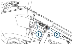
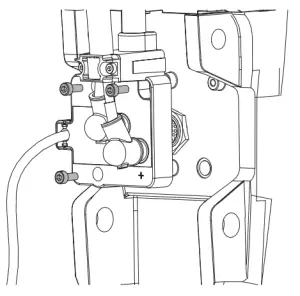
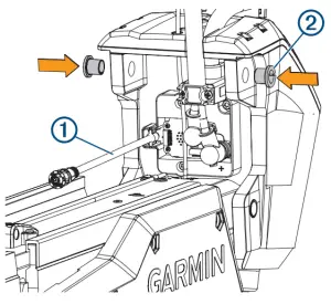
- Disconnect the cable from the display panel on the upper link of the mount .

- Using two 4 mm hex bits or wrenches, remove the screw and washer from one side of the upper pin on the steering servo housing.TIP: It is helpful to use the other 4 mm hex wrench to holdone end of the upper pin stationary while you remove thescrew.
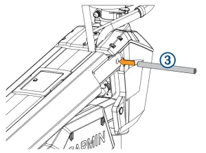
- Remove the upper pin from the steering servo housing.NOTICETake care when you remove the upper pin, because themotor swings freely on the lower pin and may damage thedrive motor, propeller, or trailer.
 TIP: It is helpful to use the other 4 mm hex wrench to holdone end of the upper pin stationary while you remove thescrew.
Removing the Cable-Junction Box from the Steering Servo Housing
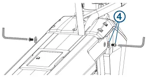
- Using a 4 mm hex bit or screwdriver, remove the three screws that secure the cable-junction box to the steering servo housing.NOTE: You may have to lift up on the upper link as much as allowed by the power cable to access the screws that secure the cable-junction box.
- Carefully pull the cable-junction box away from the steering servo housing to remove it.NOTICEThe cable-junction box connects to a PCB in the steering servo housing. When removing the box, take care to avoid damaging the connector on the PCB.
 NOTE: You may have to lift up on the upper link as much as allowed by the power cable to access the screws that secure the cable-junction box.
Examining the Cable-Junction Box for Potential Water Intrusion
![]() CAUTION
CAUTION
It is critical that you examine the back of the cable-junction box for evidence of water intrusion after you disconnect it from the steering servo housing. If evidence of water intrusion is present, you must not continue with this service.
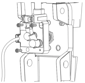
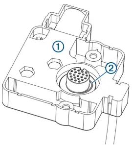
- Examine the back of the cable-junction box for any evidence of moisture, especially in the cavity around the connector .
- Select an action:
- If no moisture is present, continue with this service.
- If any moisture is present on the back of the cable-junction box or in the cavity around the connector, stop this service and contact Garmin® product support for assistance.
Installing the Gasket and Washers on the Steering Servo Housing
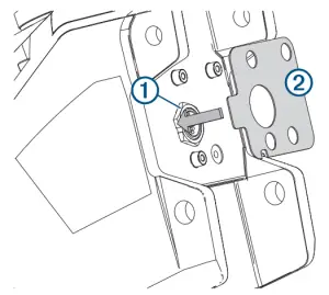
- Using a damp cloth, lightly clean the surface of the steering servo housing around the connector .
- Remove the adhesive backing from the large square gasket included in the kit.
- Align the holes for the screws and connector, and press the gasket against the steering servo housing to adhere it in place.
- Remove the adhesive backing from one of the smallest washers included in the kit.
- Place the washer, adhesive-side down, over one of the three screw posts on the steering servo housing, and press to adhere it in place.
- Repeat the previous two steps for the other two screw posts.
Removing the Existing O-ring and Installing the New Connector Seals
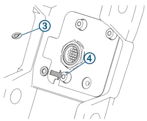
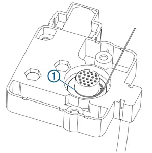
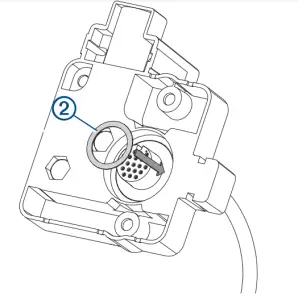
- On the back of the cable-junction box, remove the existing Oring around the connector.
- Position the small round flat seal (without adhesive) from the kit around the connector on the cable-junction box, and press downward until it is firmly in place.
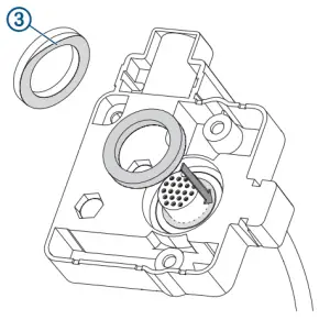
- Remove the liner from the adhesive backing on the thick round seal from the kit, position it around the connector on the cable-junction box, adhesive-side down, and press downward until it is firmly in place.
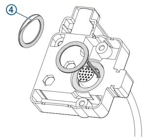
- Remove the liner from the adhesive backing on the thin round seal from the kit, position it around the connector on the cable junction box, adhesive-side down, and press downward until it is firmly in place.
Reconnecting the Cable-Junction Box to the Steering Servo Housing
- Examine the back of the cable-junction box and, if necessary, clean any dust or water deposits using a damp cloth.
- Carefully align the connector on the back of the cablejunction box with the connector on the steering servo housing, and gently press it in place.NOTICEWhen reconnecting the cable-junction box, take care when aligning the connectors before pushing to avoid damaging them.
- Using a 4 mm hex bit or screwdriver, install and tighten the three screws that secure the cable junction box to the steering servo housing.
Connecting the Upper Link of the Mount to the Steering Servo Housing
- Make sure the data cable is accessible and is not trapped by any part of the mount.
- Make sure the bushings are in place in the upper holes on the steering servo housing.
- Tip the top of the steering servo housing inward to align the holes on the upper link and the housing.
- Push the pin through the holes on the upper link of the mount and the steering servo housing.
- Using a 4 mm hex bit or hex wrench, secure the pin using the screws and washers on both sides.NOTE: To properly secure the pin, you should use two hexbits or wrenches so the pin does not rotate as you tighten the screws.
- Reconnect the cable to the display panel on the upper link of the mount.
 NOTE: To properly secure the pin, you should use two hexbits or wrenches so the pin does not rotate as you tighten the screws.
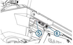
© 2020 Garmin Ltd. or its subsidiaries
References
[xyz-ips snippet=”download-snippet”]