![]() GC™12INSTALLATIONINSTRUCTIONS
GC™12INSTALLATIONINSTRUCTIONS
Mounting Considerations
You can mount the camera upside-down or sideways. You can reverse the camera image to use in rearview mode. See your Chartplotter owner’s manual for instructions.You should mount the camera in a location where it is
- not an obstacle in doorways or walkways.
- not exposed to extreme temperatures.
- not exposed to gas or oil.
- not exposed to radioactivity.
- not facing direct sunlight or a direct reflection of sunlight.
Tools Needed
- 1 A fuse or circuit breaker
- Drill and 2 mm (1/16 in.) drill bit
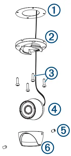
Mounting the Camera
- Secure the template
1to the mounting location.
- Using a 2 mm (1/16 in.) drill bit, drill the pilot holes.
- Adjust the dome base
2to the correct orientation for your desired camera tilt. - Secure the dome base to the mounting location using the included tapping screws
3. - Insert the camera
4into the dome base. - Secure the set screws
5into the dome front6using the included wrench.
Installation Considerations
You must connect the camera power wire to the battery through a 1 A fuse or circuit breaker. If you do not use a fuse or circuit breaker, the camera can malfunction.Some Garmin® GPSMAP® chart plotters have a built-in CVBS video encoder. Video from the camera or cameras appears on all chart plotters on the network when plugged into a single CVBS IN port. Go to garmin.com/gc12 for a list of compatible GPSMAP chart plotters.If you want to use more than one camera or the Chartplotter does not have a CVBS IN port, you must use an encoder.You can add up to four cameras to one encoder and up to two encoders to the Garmin Marine Network.NOTE: To reduce the possibility of interference, you can install a composite video ground loop isolator (not included) between the camera and any chart plotters that do not have isolated power grounds.
Installation Diagram
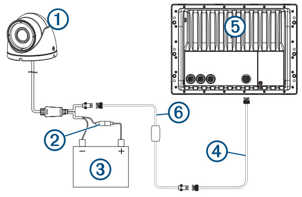
| 1 | GC 12 |
| 2 | 1 A fuse or circuit breaker (not included)1 |
| 3 | 12 Vdc power source |
| 4 | BNC to BNC coaxial video cable (not included) |
| 5 | Compatible Garmin chartplotter |
| 6 | Composite video ground loop isolator (not included) |
Installation With Encoder Diagram
You can add more than one camera to your network when you use an encoder.
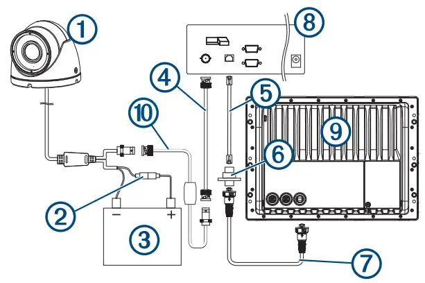
| 1 | GC 12 |
| 2 | 1 A fuse or circuit breaker (required, not included)1 |
| 3 | 12 Vdc power source |
| 4 | BNC to BNC coaxial video cable (not included) |
| 5 | Network cable |
| 6 | Power-over-Ethernet isolation coupler (GPN 010-10580-10) |
| 7 | Garmin Marine Network cable |
| 8 | Axisa Q7424 Encoder (optional/not included) |
| 9 | Compatible Garmin chartplotter |
| 10 | Composite video ground loop isolator (not included) |
¹You must connect the camera power wire to the battery through a 1 A fuse or circuit breaker. If you omit a fuse or circuit breaker, the camera can malfunction.

GUID-A4093A3F-E824-457D-BFB5-8DE2389473AC v2January 2021
Troubleshooting
Video Does Not Appear on the Chartplotter Screen
- Verify all cables are firmly connected.
- Verify the video cable is connected to the camera video output port.
The image on the Chartplotter Screen is Dim or Dark
- Verify the lens is clean. If necessary, wipe the lens with a soft, clean cloth.
- If the camera is exposed to too much direct light, change the camera position or location.
- Adjust the contrast on your Chartplotter. See your Chartplotter manual for instructions.
Image on the Chartplotter Screen Flickers
- Verify the camera points away from the sun.
- Adjust the contrast on your Chartplotter. See your Chartplotter manual for instructions.
The camera is Not Working and the Surface is Hot
- Verify the camera is connected to an appropriate power source.
Video Image Includes Scrolling Bars on the Chartplotter Screen
- Verify all cables are firmly connected.
- Install a composite video ground loop isolator (not included) between the camera and any Chartplotter that does not have an isolated power ground.
Specifications
| Dimensions (W x H) | 50.5 x 44.3 mm (2 x 1 3/4 in.) |
| Weight | 205 g (7.23 oz) |
| Operating temperature | From -10 to 50°C (from 14 to 122°F) |
| Water rating | IEC 60529 IPX71 |
| Operating current | 12 VdcIR off: 80 mA IR on 170 mA |
| Storage temperature | From -15 to 60°C (from 5 to 140°F) |
| Power input | From 9 to 18 Vdc |
| Compass-safe distance | 155 mm (6.125 in.) |
| Viewing angle | Vertical: 52 degrees Horizontal: 69 degrees |
| IR distance | 10 m (33 ft.) |
| Video output | 1.0Vp-p composite 75 0 composite |
| Resolution | PAL |
| Effective pixels | Vertical: 582 Horizontal: 976 |
© 2019 Garmin Ltd. or its subsidiariesGarmin®, the Garmin logo, and GPSMAP® are trademarks of Garmin Ltd. or its subsidiaries, registered in the USA and other countries. GC™ is a trademark of Garmin Ltd. or its subsidiaries. These trademarks may not be used without the express permission of Garmin.Axis® is a registered trademark of Axis AB.¹The device withstands incidental exposure to water of up to 1 m for up to 30 min.For more information, go to www.garmin.com/waterrating.© 2019 Garmin Ltd. or its subsidiariessupport.garmin.com
References
Water Rating Definitions | Garmin
GC™ 12 | Marine Camera | Boat Camera | GARMIN Close Close IE Banner Garmin on Facebook Garmin on Twitter Garmin on YouTube Garmin on Pinterest Garmin on Instagram
GC™ 12 | Marine Camera | Boat Camera | GARMIN Close Close IE Banner Garmin on Facebook Garmin on Twitter Garmin on YouTube Garmin on Pinterest Garmin on Instagram
Garmin Customer Support
[xyz-ips snippet=”download-snippet”]