
GARMIN Integrated Avionics System
Website Address: www.garmin.comExcept as expressly provided herein, no part of this manual may be reproduced, copied, transmitted, disseminated, downloaded or stored in any storage medium, for any purpose without the express written permission of Garmin. Garmin hereby grants permission to download a single copy of this manual and of any revision to this manual onto a hard drive or other electronic storage medium to be viewed for personal use, provided that such electronic or printed copy of this manual or revision must contain the complete text of this copyright notice and provided further that any unauthorized commercial distribution of this manual or any revision hereto is strictly prohibited. Garmin® is a registered trademark of Garmin International, Inc. or its subsidiaries. This trademark may not be used without the express permission of Garmin.
WARNING: The displayed minimum safe altitudes (MSAs) are only advisory in nature and should not be relied upon as the sole source of obstacle and terrain avoidance information. Always refer to current aeronautical charts for appropriate minimum clearance altitudes.WARNING: The altitude calculated by GPS receivers is geometric height above Mean Sea Level and could vary significantly from the altitude displayed by pressure altimeters, such as the GDC 74A Air Data Computer, or other altimeters in aircraft. GPS altitude should never be used for vertical navigation. Always use pressure altitude displayed by the PFD or other pressure altimeters in aircraft.WARNING: Do not use outdated database information. Databases used in the system must be updated regularly in order to ensure that the information remains current. Pilots using any outdated database do so entirely at their own risk.WARNING: Do not use basemap (land and water data) information for primary navigation. Basemap data is intended only to supplement other approved navigation data sources and should be considered as an aid to enhance situational awareness.WARNING: For safety reasons, operational procedures must be learned on the ground.WARNING: The Garmin system, as installed in this aircraft, has a very high degree of functional integrity. However, the pilot must recognize that providing monitoring and/or self-test capability for all conceivable system failures is not practical. Although unlikely, it may be possible for erroneous operation to occur without a fault indication shown by the system. It is thus the responsibility of the pilot to detect such an occurrence by means of cross-checking with all redundant or correlated information available in the cockpit.WARNING: The United States government operates the Global Positioning System and is solely responsible for its accuracy and maintenance. The GPS system is subject to changes which could affect the accuracy and performance of all GPS equipment. Portions of the Garmin system utilize GPS as a precision electronic NAVigation AID (NAVAID). Therefore, as with all NAVAIDs, information presented by the system can be misused or misinterpreted and, therefore, become unsafe.WARNING: To reduce the risk of unsafe operation, carefully review and understand all aspects of the Pilot’s Guide documentation and the approved aircraft documentation. Thoroughly practice basic operation prior to actual use. During flight operations, carefully compare indications from the system to all available navigation sources, including the information from other NAVAIDs, visual sightings, charts, etc. For safety purposes, always resolve any discrepancies before continuing navigation.NOTE: All visual depictions contained within this document, including screen images of the panel and displays, are subject to change and may not reflect the most current system and aviation databases. Depictions of equipment may differ slightly from the actual equipment.NOTE: Garmin requests the flight crew report any observed discrepancies related to database information. These discrepancies could come in the form of an incorrect procedure; incorrectly identified terrain, obstacles and fixes; or any other displayed item used for navigation or communication in the air or on the ground. Go to FlyGarmin.com and select ‘Report An Aviation Data Error Report.’
| Record of Revisions | ||||
| Part Number | Revision | Date | Page Range | Description |
| 190-00760-00 | A | March 2007 | i through vi,
S-1 through S-12 |
Production Release |
| 190-00760-00 | B | May 2007 | All | Revised Garmin UK Address |
| 190-00760-00 | C | May 2011 | All | Added circle search pattern functionality |
| 190-00760-00 | D | May 2015 | All | Updated to include latest software and all Garmin integrated avionics systems |
SEARCH AND RESCUE
NOTE: The Search and Rescue (SAR) feature must be purchased and activated before use. Contact a Garmin-authorized service center for configuration and a Secure Digital (SD) unlock card. If Search and Rescue is not enabled, it is not visible on any display pane, screen, or menu.
Instructions are presented here for quickly and easily incorporating search patterns into a flight plan. The Search and Rescue feature has four basic search patterns (Parallel Track, Sector, Expanding Square, and Circle) to provide air crews with step by step tracking procedures for the search and rescue mission.
All patterns have adjustable parameters. The most effective pattern may be chosen based on available information about the search object, the weather, and the terrain. Typical flight planning parameters such as time, speed, distance, and fuel remaining are given throughout the search mission on the flight plan pages.
SEARCH AND RESCUE SD UNLOCK CARD:The Search and Rescue feature is enabled with a dedicated Secure Digital (SD) unlock card that is inserted into the top SD card slot on the MFD. If SAR configuration is enabled, the SAR flight patterns are available as part of an active flight plan.Refer to the Garmin Integrated Avionics System Pilot’s Guide for your airframe for more information on SD cards.
SEARCH AND RESCUE FLIGHT PLANS:A Search and Rescue flight plan is a route that systematically covers an area for a search mission.
NOTE: When turning on the system for use, the system remembers the last type of search pattern used and the track state prior to shutdown. Once the default settings have been changed, the system retains the new data.
The search patterns may be hand flown or coupled to the Garmin Automatic Flight Control System (AFCS). Refer to the Garmin Integrated Avionics System Pilot’s Guide for more information about the AFCS (if installed) and Flight Management.The Search and Rescue flight plan is configured on the Search and Rescue Menu (on the MFD) or the Search and Rescue Screen (on the Touchscreen Controller). All SAR flight plans must begin with a waypoint to ‘anchor’ the search pattern. Any waypoint may be used to anchor a search pattern, including user defined waypoints.The search patterns have adjustable parameters to modify the size and direction of the pattern. Default values appear initially for each type of pattern.
PARALLEL TRACK SEARCH PATTERN
The Parallel Track Search Pattern (default) is a rectangular pattern that traverses a defined path over the ground in a systematic manner as shown in the figure below. The Parallel Track Search Pattern may begin at any designated waypoint and will continue through the route based upon pilot-entered parameters.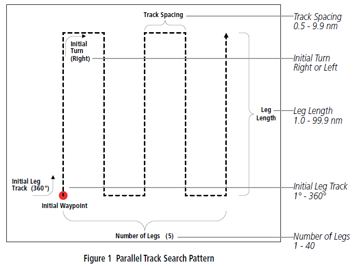
| Parallel Track Parameters | Default Value | Range of Values (resolution) |
| Initial Track | 360° | 1 – 360 (1°) |
| Initial Turn | Left | Left, Right |
| Leg Length | 15 nm | 1.0 – 99.9 (0.1 nm) |
| Track Spacing | 1.0 nm | 0.5 – 9.9 (0.1 nm) |
| Number of Legs | 10 | 1 – 40 (1) |
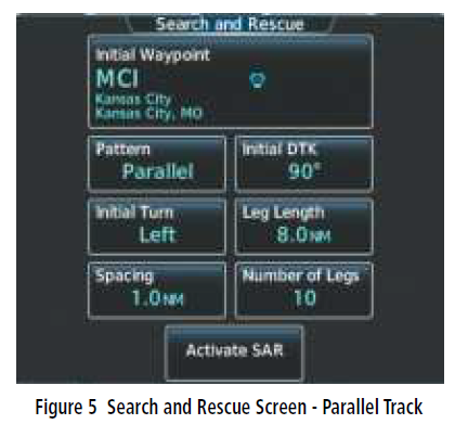
The parallel track flight plan begins with a waypoint to anchor the corner of the search pattern. In the following example (Figure 3), the search requires a wide path over part of western Missouri. KMCI is the crew-selected waypoint from which the Parallel Track Search Pattern begins.
The default entries have been modified in the illustration to fly an initial desired track of 90° with an initial turn to the left. The leg lengths are 8.0 nm with spacing of 1.0 nm between them, and the number of legs is ten.
Creating a parallel track search pattern on the MFD:
- Press the FPL Key on the MFD to display the Active Flight Plan Page.
- If desired, scroll to highlight a flight plan waypoint. It will be selected as the anchoring waypoint and inserted into the WAYPOINT field.
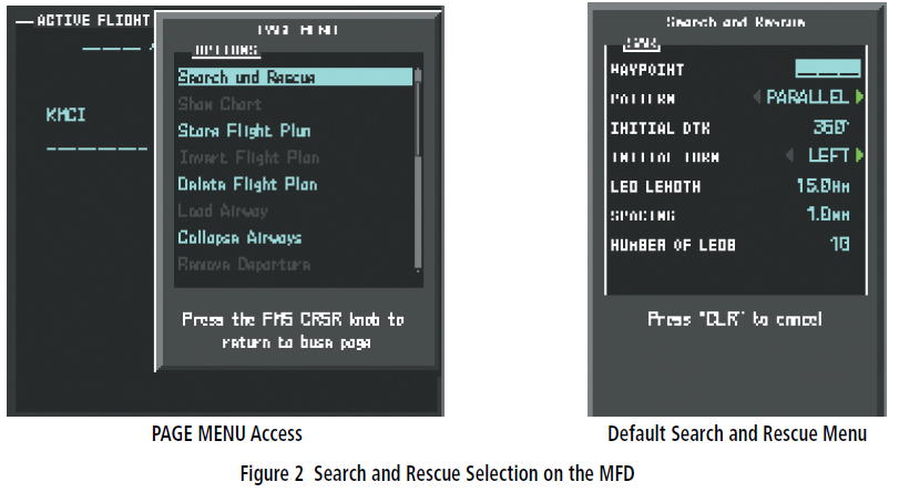
- Press the MENU Key to display the PAGE MENU OPTIONS (Figure 2).
- Scroll through the choices with the FMS Knob to select ‘Search and Rescue’.
- Press the ENT Key to complete the selection and view the Search and Rescue Menu. The WAYPOINT field will be highlighted with either the selected waypoint or dashes shown.
- Rotate the large and small FMS Knobs to enter the initial waypoint, if required (Figure 3). Press the ENT Key to complete the selection and highlight the ‘PATTERN’ field.
- Rotate the small FMS Knob to select ‘PARALLEL’. Press the ENT Key to highlight the ‘INITIAL DTK’ field.
- Rotate the FMS Knobs to select the initial desired track, or leave the default entry. Press the ENT Key to highlight the ‘INITIAL TURN’ field.
- Rotate the small FMS Knob to select ‘LEFT’ or ‘RIGHT’. Press the ENT Key to highlight the ‘LEG LENGTH’ field.
- Rotate the FMS Knobs to select the leg length, or leave the default entry. Press the ENT Key to highlight the ‘SPACING’ field.
- Rotate the FMS Knobs to select the leg spacing, or leave the default entry. Press the ENT Key to highlight the ‘NUMBER OF LEGS’ field.
- Rotate the small FMS Knob to select the number of legs. Press the ENT Key to highlight ‘ACTIVATE SAR?’.
- Press the ENT Key with the ‘ACTIVATE SAR?’ field highlighted to complete and activate the flight plan search pattern.

Creating a parallel track search pattern on the Touchscreen Controller:
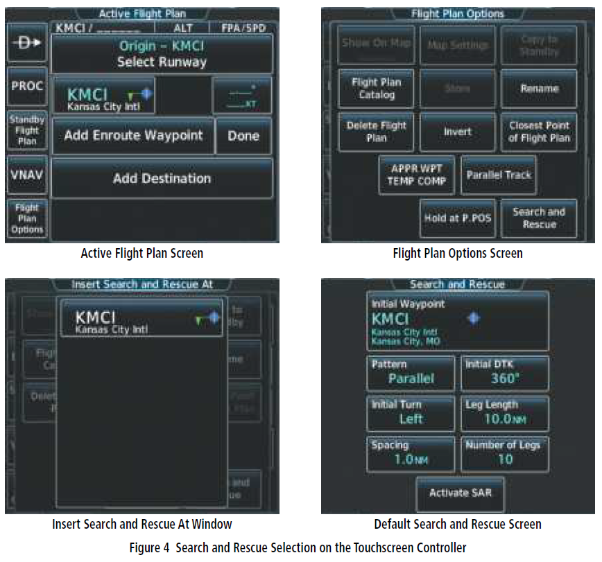
- From Home, touch Flight Plan > Flight Plan Options > Search and Rescue to display the Insert Search and Rescue At Window. The active flight plan waypoints will be listed in the window.
- Scroll the window, if necessary, and touch the desired waypoint selection button. The Search and Rescue Screen is displayed with the selected waypoint as the initial waypoint for the search pattern, and the default selections for the parameters (Figure 4).

- Modify any combination of the following parameters, as required: When complete, go to step 4.
- Touch the Initial Waypoint Button if a different Initial Waypoint is desired. Use the keypad to select the initial waypoint. Touch the Enter Button to complete the selection and return to the Search and Rescue Screen.
- Touch the Pattern Button to display the Search and Rescue Pattern Screen. Touch the Parallel Button to select the parallel track pattern and return to the Search and Rescue Screen.
- Touch the Initial DTK Button to display the keypad. Touch the keypad buttons to select the initial desired track. Touch the Enter Button to complete the selection and return to the Search and Rescue Screen.
- Touch the Initial Turn Button to display the Search and Rescue Initial Turn Screen. Touch the Left Button or Right Button to select the initial turn direction and return to the Search and Rescue Screen.
- Touch the Leg Length Button to display the keypad. Touch the keypad buttons to select the length of each leg. Touch the Enter Button to complete the selection and return to the Search and Rescue Screen.
- Touch the Spacing Button to display the keypad. Touch the keypad buttons to select the spacing between each leg. Touch the Enter Button to complete the selection and return to the Search and Rescue Screen.
- Touch the Number of Legs Button to display the keypad. Touch the keypad buttons to select the number of legs. Touch the Enter Button to complete the selection and return to the Search and Rescue Screen.
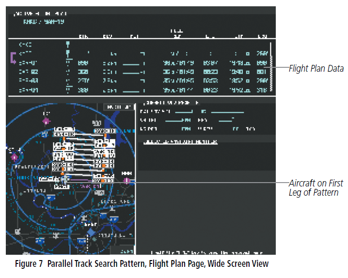
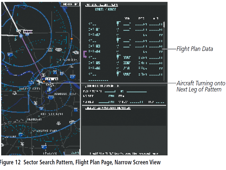
- Touch the Activate SAR Button to activate the flight plan search pattern (Figure 5).Once the flight plan is activated, the pattern appears on the map pages (Figure 6 and 7) and is flown like any other flight plan. The waypoints are numbered to indicate the sequence to be flown. A turn anticipation arc is shown in the corners of the pattern, based on the aircraft ground speed.If the search pattern needs to be changed after being activated, follow the procedure to create a search pattern to return to the Search and Rescue Menu or Search and Rescue Screen. The parameters previously entered will still be selected on the Search and Rescue Menu. Make the changes and activate the corrected search pattern.
 Once the flight plan is activated, the pattern appears on the map pages (Figure 6 and 7) and is flown like any other flight plan. The waypoints are numbered to indicate the sequence to be flown. A turn anticipation arc is shown in the corners of the pattern, based on the aircraft ground speed.
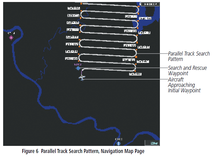
 If the search pattern needs to be changed after being activated, follow the procedure to create a search pattern to return to the Search and Rescue Menu or Search and Rescue Screen. The parameters previously entered will still be selected on the Search and Rescue Menu. Make the changes and activate the corrected search pattern.
SECTOR SEARCH PATTERN
The Sector Search Pattern consists of three triangular sectors, each composed of three legs as shown in Figure 8. The Sector Search Pattern begins at any designated waypoint and proceeds through the route based upon pilot-entered parameters.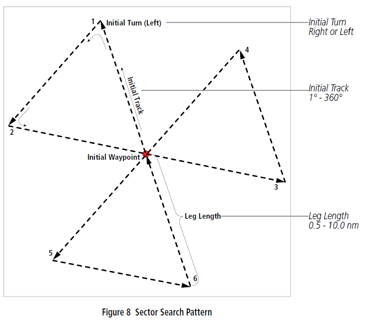
| Sector Parameters | Default Value | Range of Values (resolution) |
| Initial Track | 360° | 1 – 360 (1°) |
| Initial Turn | Left | Left, Right |
| Leg Length | 5.0 nm | 0.5 – 10.0 (0.1 nm) |
The initial waypoint defines the center of the sector pattern, but is not numbered as one of the SAR waypoints. Each of the three sectors is an equilateral triangle, with each side of the triangle one leg length long.The Sector Search Pattern can be created on the MFD or on the Touchscreen Controller with the same procedure as the Parallel Track Search Pattern, except there are no settings for track spacing or number of legs. In this modified example, the initial desired track is 90 degrees, the turns are to the left and the leg length is 10.0 nm.

Upon flight plan activation, the pattern appears on the map pages. A turn anticipation arc is shown in the corners of the pattern, based on the aircraft ground speed. The waypoints are numbered to indicate the sequence to be flown.
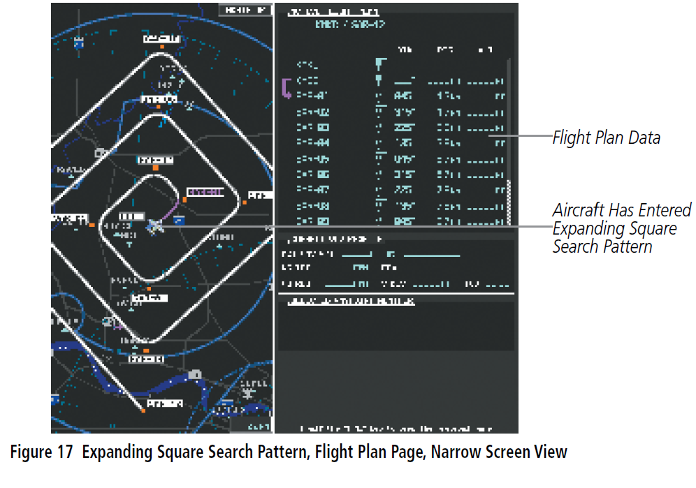
EXPANDING SQUARE SEARCH PATTERN
The Expanding Square Search Pattern consists of a square-shaped route that begins at a designated waypoint and continually expands away from the center (Figure 13). The waypoints are numbered to indicate the sequence to be flown.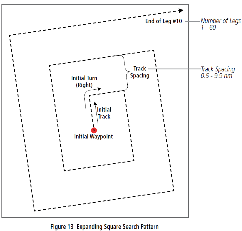
| Expanding Square Parameters | Default Value | Range of Values (resolution) |
| Initial Track | 90° | 1 – 360 (1°) |
| Initial Turn | Left | Left, Right |
| Track Spacing | 1.0 nm | 0.5 – 9.9 (0.1 nm) |
| Number of Legs | 10 | 1 – 60 (1) |
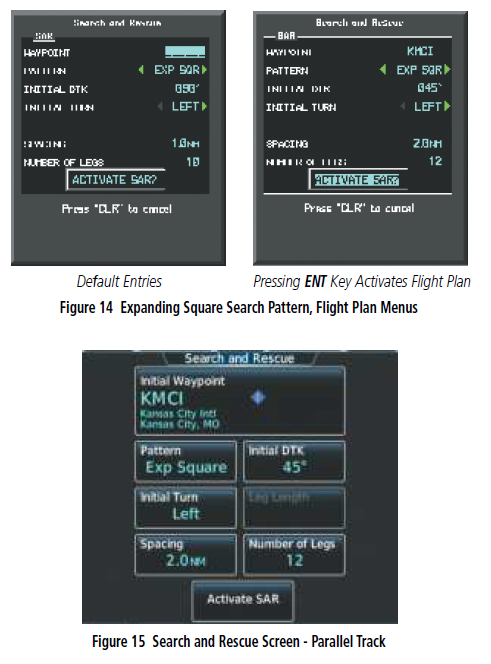
The Expanding Square Search Pattern can be created on the MFD or on the Touchscreen Controller with the same procedure as the Parallel Track Search Pattern, except there is no settings for leg length. The length of each leg is calculated based on track spacing.
In the example shown, the parameters were modified to an initial track of 45 degrees, turns are to the left, 2.0 nm track spacing, and 12 legs.
The search pattern is displayed on the map pages when the flight plan is activated. A turn anticipation arc is shown in the corners of the pattern, based on the aircraft ground speed. The aircraft flies to the numbered waypoints in sequence around the center waypoint of the pattern.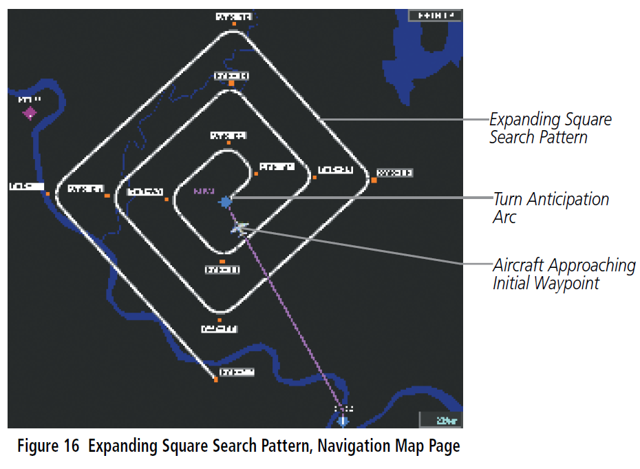
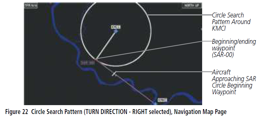
CIRCLE SEARCH PATTERN
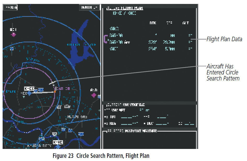
The Circle Search Pattern is centered around a designated waypoint based on user-entered parameters (turn direction and radius). The beginning/ending waypoint is numbered SAR-00. Unlike the other search patterens, the system does not fly to the designated waypoint first, and then fly the search pattern. The system will fly to the calculated SAR-00 entry point. The turn direction selected determines the location of the SAR-00 entry point to intiate a clockwise (RIGHT) or counter-clockwise (LEFT) path around the circle. A circular search pattern is displayed on the map pages when the flight plan is activated.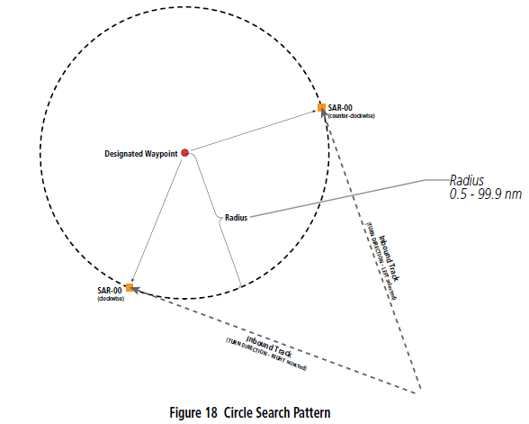
| Circle Parameters | Default Value | Range of Values (resolution) |
| Initial Turn | Left | Left, Right |
| Radius | 1.0 nm | 0.5 – 99.9 (0.1 nm) |
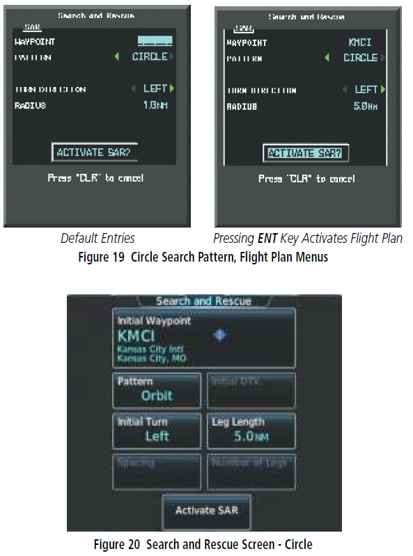
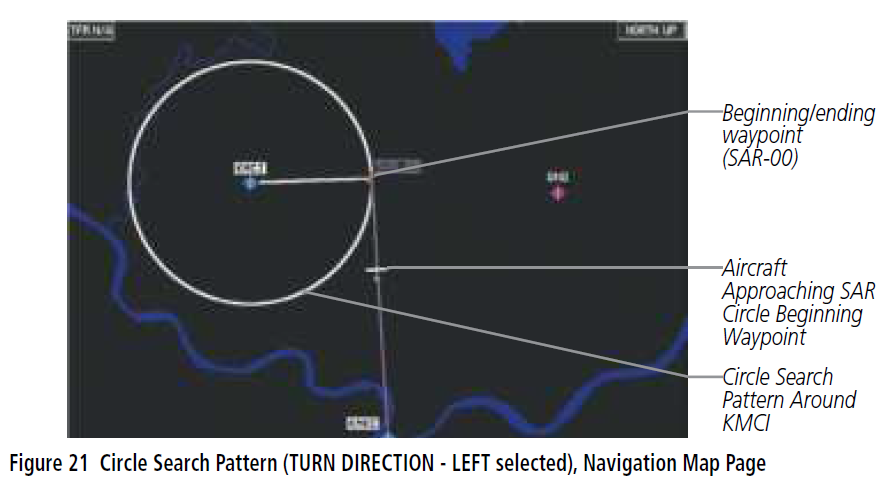
The Circle Search Pattern can be created on the MFD or on the Touchscreen Controller with the same procedure as the Parallel Track Search Pattern, except there are only settings for turn direction and radius of the circle.In the example shown, the parameters were modified to a circle with a radius of 5.0 nm centered on the KMCI.

References
[xyz-ips snippet=”download-snippet”]