![]() PRODUCT USER MANUAL
PRODUCT USER MANUAL
![]()
 http://gatordriverassist.com/grv50kt
INTRODUCTION
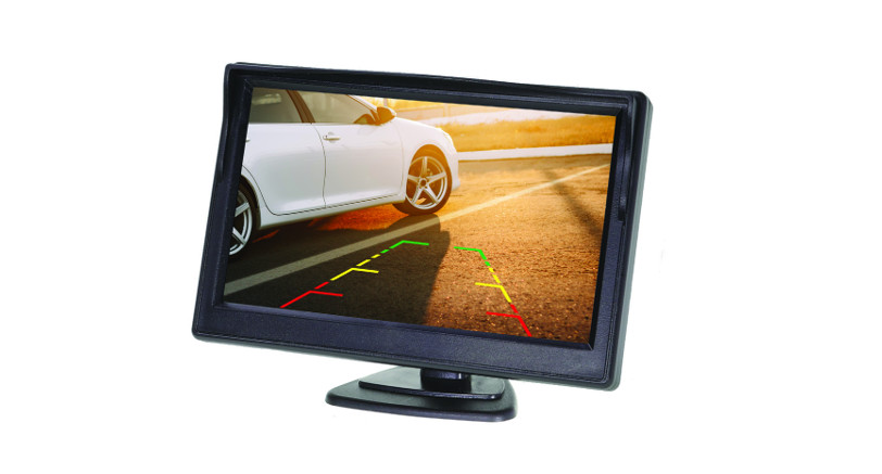
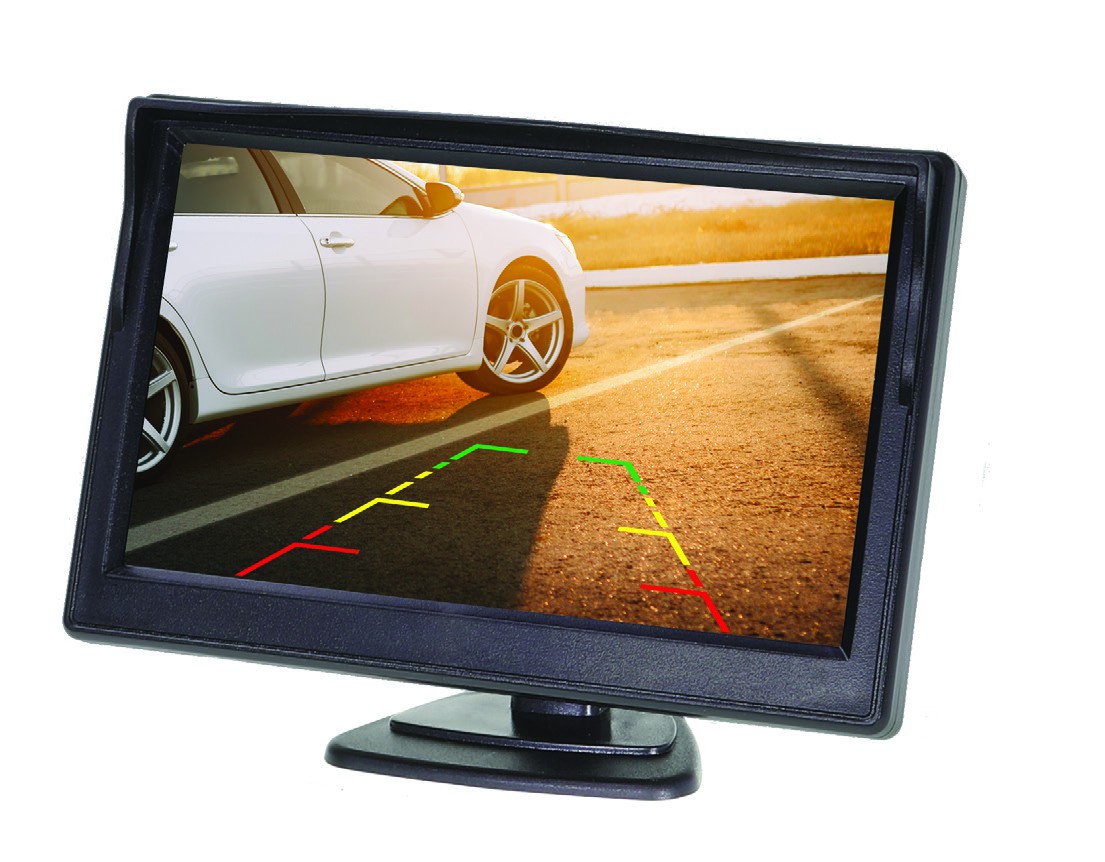
WELCOMEThank you for purchasing the Gator GRV50KT 5.0″ Monitor + Reverse Camera. Please ensure that you have read the product manual and instructions in full, prior to installation and use. Failure to do so may result in product failure/damage or incorrect operation and therefore impact the product performance.
PRODUCT FEATURES
- Monitor
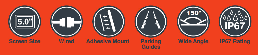
- 5.0″ 16:9 High-resolution LCD screen
- Resolution 480*272 · 12V Compatible
- Secondary Video RCA Input
- Dimensions 90(H) x 125(W) x 44mm(L)
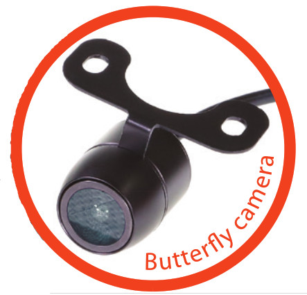
- Butterfly Camera
- 150 Degree wide angle lens
- Parking guide lines
- IP-67 Dust and water protection
- CMOS Sensors
- 0.2 Lux
- NTSC/PAL
- 5.5M Video extension cable with trigger
PACKAGE COMPONENTS
Parts supplied include:
- Monitor
- Butterfly mount camera
- 5.5M RCA extension cable
- Instruction manual
- Monitor harness
- Camera harness
INSTALLATION
Installation diagramThe video signal is transferred from the camera to the GRV50KT monitor via an RCA cable that will need to be run through the boot, through the passenger compartment to the mirror monitors wired loom run under the dash. From there the power and video signals are sent directly to the monitor. At the rear of the car the camera is powered directly from the reversing tail light. Priority is the AV2 input.
Installing the camera
In most instances, the camera is best mounted above the vehicles license plate as shown here.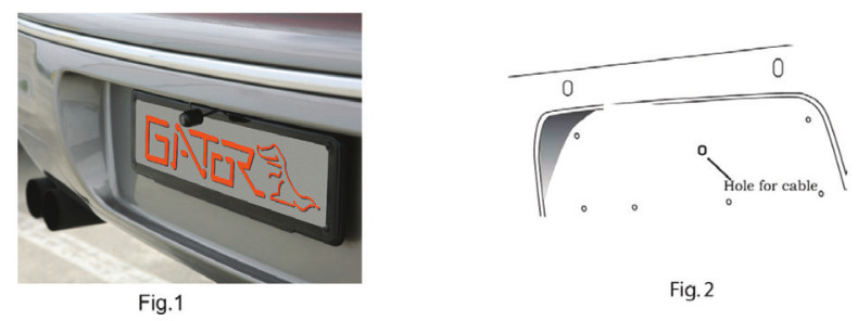
- Connect the RED wire of the Cameras Power Harness to the wire that supplies power to the reversing light globe (the wire that is energized only when the car is put into reverse). Before making the electrical connection, temporarily disconnect the camera from the power plug whilst making the connection to the reversing light globe. Use a suitable splicing/crimp connector (scotch lock type) or strip connector. This connection can also be soldered, making sure to insulate the joint with electrical insulation when done. The camera has only one wire to connect (positive (+). There is no need to hook up a ground earth wire as the camera gets its earth through the RCA cable. Hooking up the ground earth may cause a ground loop. In this case horizontal lines will appear in the image.NOTE: CAN BUSIn the event that the cars reversing lights are driven by CAN BUS the above wiring system may not trigger the system correctly. It may even create a globe fault warning. In this case a CAN BUS module (sold separately) may need to be installed. However, just because the vehicle has a CAN BUS system does not necessarily mean that it will require such a module to work. In fact the opposite is true. Most vehicles do not require an additional module. If a CAN BUS module is required we recommend seeking advice from a professional installer.Installing the camera….cont
- After you have insulated the join you can connect the power harness to the camera.NOTE: Some cars that run LED or computer controlled lighting systems may not deliver enough voltage to run the camera. If the voltage at the reversing wire light is less than +12 volts it may be necessary to use a relay to supply power to the transmitter harness from the wiring in the front of the car. In this case the reversing light only needs to trigger the relay. Make sure that you do not drill holes in the panels that have an opposite face that is visible outside the car for example guard panels. In fact, whenever drilling holes in the bodywork of a vehicle, always see what is on the other side.
- Connect one end of the supplied RCA cable to the RCA socket from the camera, then run the RCA cable to the front under side of the driver side dash board. This is where the monitor’s loom will be located. To do this you will need to remove the rear seat to pass the cable into the cabin area and you will need to remove the door scuff plates to run the wire along the side of the vehicle. The RCA cable will be hidden when you replace the scuff plates. When the cable is at the front of the vehicle the RCA cable needs to be run from the scuff plate area to the underside of the dash behind the kick trim (remove and run cable).
- The monitor has two power wires to be connected. Connect the red wire (accessories +12V) to a wire that is energized when the vehicles accessories is turned on. Connect the black wire to a ground earth wire or to the body of the car using the steel of the cars body behind the kick trim as an earth. In this case drill a small hole and connect the wire using a suitable ring terminal. Scrape off the cars paint around the hole to ensure good earth.
- Connect the RCA cable to the RCA socket from the monitors loom.
TESTING THE REVERSE CAMERA FUNCTION
- Engage the park brake and turn the ignition key to the on position. DO NOT start the vehicle.
- Select reverse gear with the gear shift. The monitor will sense the video signal from the camera automatically and will display the camera’s image of the rear of the vehicle.
Menu options and settings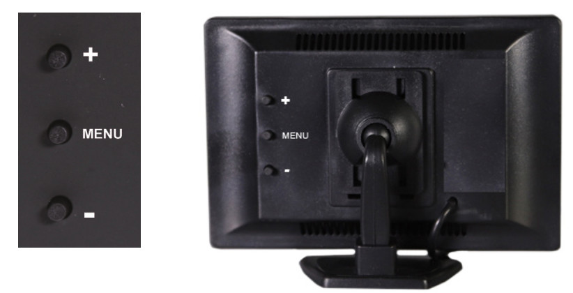
- Press the Menu button to access functions
- Press the + or – button to confirm selection– Brightness: Adjusts screen brightness (50 – 100)– Contrast: Adjusts screen contrast (50 – 100)– Saturation: Adjusts screen saturation (50 – 100)– Language: Select menu language– Mode: Changes display mode between 16:9 & 4:3 ratio– Reset: Resets all menu setting back to factory configuration
PRODUCT SPECIFICATIONS
Monitor– Size: 5.0 inch colour TFT LCD Screen– Resolution : 480*272 (500 Candela)– Video Input : Yellow = Reverse Camera Input– Supply Power: DC12V +/- 10%– NTSC/PAL
Butterfly Camera– Aluminum case & waterproof for outdoor use.– IP67 Standard– Lense Angle 150 degree– Low-Lux CMOS camera– Parking guidelines– NTSC
TECHNICAL ASSISTANCE
If you need assistance setting-up or using your Gator product now or in the future, call Gator Support.
![]() AustraliaTEL: 03 8587 8898FAX: 03 8587 8866Mon-Fri 9am 5pm AESTPlease retain this user guide for future reference.
AustraliaTEL: 03 8587 8898FAX: 03 8587 8866Mon-Fri 9am 5pm AESTPlease retain this user guide for future reference.
If you would like to download a digital copy of this manual, or other Gator manuals/ software, please visit the http://gatordriverassist.com website and click on `Firmware & Manuals” for information on where to find the manuals/software. This manual is considered correct at time of printing but is subject to change. For latest manuals and updates refer to the website. Copyright
© 2017 by TDJ Australia All rights reserved. No part of this publication may be reproduced, distributed, or transmitted in any form or by any means, including photocopying, recording, copying or other electronic or mechanical methods, without the prior written permission of the author.
References
[xyz-ips snippet=”download-snippet”]