
Gator UniversaL hard wiring kit
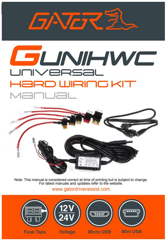
IntroductionThank you for purchasing the Gator GUNIHWC universal hardwiring kit. The GUNIHWC has been designed to safely hardwire & power Dash Cams or devices with Micro or Mini USB. Please ensure that you have read the product manual and instructions in full, prior to installation and use. Failure to do so may result in product failure/damage or incorrect operation and therefore impact the product performance.
Product features
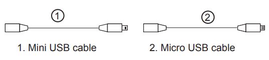
- Mini USB adapter
- Micro USB adapter
- 4 Metre cable length
- 5 Kinds of blade fuse taps with fuses standard, mini, micro, micro2, and micro3
- 12/24V
- Short circuit, temperature, voltage, reverse connect, and overload protection
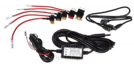
Product components
Product information
The GUNIHWC Hardwire Kit is a simple plug-and-play solution to hardwire any Dash Cam or device using Mini or Micro USB for power. The Hardwire Kit is compatible with 12V/24V DC for car or truck installations.NOTE:Refer to your vehicle owner’s manual to determine.
- Location of the fuse box
- How to access the fuse box
- The type of fuse tap required
It is highly recommended that you have a quick read of the installation instructions in this manual. If you are not comfortable with the process please seek further assistance from an authorized technician. Since the power to your Dash Cam will be running via a power cable from the fuse box you will need to determine your vehicle’s fuse box location. Most vehicles have a fuse box underneath the dashboard on the driver’s side which is easily accessible below the steering column (behind a removable panel). However, the location does vary between vehicle make and model. There are 5 types of fuse tap cables included in this kit. Check to see if these fuses suit your vehicle’s fuse box. If none are suitable you will need to purchase the correct fuse to attach the hardwire kit to your vehicle’s power source. The GUNIHWC Hardwire Kit provides constant power to your Dash Cam when your vehicle is turned off. It is protected with Battery Drain Protection to safeguard your
Dash Cam from draining your vehicle’s battery. Your battery will stop providing power to your Dash Cam if your battery level gets too low.
Hardwire Kit
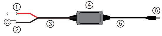
- Red power connector
- Earth/ground connector
- Input cable
- Control box with adhesive pad
- Output cable
- Output connector
Tap Fuse Options
(Only use one option for installation)
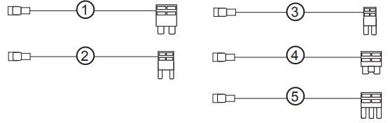
- Standard fuse cable
- Mini fuse cable
- Micro2 fuse cable
- Micro fuse cable
- Micro3 fuse cable
Adapter Options
(Only use one option for installation)
Battery drain protectionThe Hardwire Kit will protect your Dash Cam from draining your vehicle’s battery. If your vehicle’s battery voltage gets too low, GUNIHWC will stop powering your camera to save power.
Setting cut off voltage
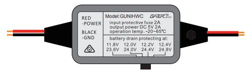
You can set the cut-off voltage according to the temperature and the capacity you’d like to consume before the hardwire kit cuts off the output. There are 4 protection settings you can set in the hardwire kit.
For 12V Batteries: The protecting voltages are 11.8V / 12.0V / 12.2V / 12.4V. 12.2V setting is recommended for most users in general driving conditions.
For 24V Batteries: The protecting voltages are 23.6V / 24.0V / 24.4V / 24.8V. 24.4V setting is recommended for most users in general driving conditions. The GUNIHWC kit will identify the lead-acid battery type automatically (12V or 24V) and protect your battery from draining accordingly.
Desired voltage cut offUse the table reference on page 7 to assist in determining your desired voltage cut-off level for battery drain protection. For example, if the temperature is 38°C and you want to keep a 75% lead-acid state capacity remaining in your battery when the hardwire kit cuts off output (meaning the battery voltage is approximately 12.402V) the cut off voltage should be set at 12.4V band. This means there will be 25% capacity in your vehicle battery which will be used for your Dash Cam while your vehicle is parked.NOTE: The table is to be used as a reference guide only in order to determine an appropriate voltage selection dependent on the vehicle’s battery age and condition.
Desired voltage cut off table

Installation diagram
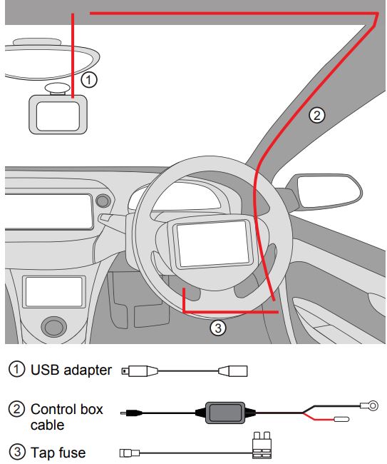
Connecting the Hardwire kit to your Dash CamThere are 2 main stages in the hardwire kit installation.1. Connecting output cable to your dashcam2. Connecting input cables to your fuse box and grounding
Attaching USB adapter to your Dash Cam1. Two Dash Cam connector cables are included with GUNIHWC one with a Mini USB plug and one with a Micro USB plug. Determine the connection interface type on your Dash Cam and then select the appropriate USB connector cable.2. Insert the USB connector cable into your Dash Cam.
Routing the output cable from the Dash Cam to the vehicles fuse box1. Consult your vehicle manufacturer for instructions on how to remove vehicle fittings for routing the hardware kit cables.NOTE: Make sure airbags are not obstructed in case of deployment.2. Once the USB connector cable is attached to your Dash Cam, it then needs to be connected to the hardwire kit’s output cable.3. The hardwire kit output cable will then need to be recessed into the roof lining where it meets the edge of the windscreen to conceal the cable.4. At the farthest end of the roof lining the output cable needs to then be routed along the A-pillar that is closest to the fuse box of the vehicle. Route the cable all the way down to the end of the A-pillar where it meets the dashboard.5. To secure use cable ties to attach the output cable to any existing cable(s) that may be housed in the A-pillar.6. Where the output cable from the A-pillar meets the side of the dashboard, the output cable will then need to be routed towards the direction of the fuse box by concealing the cable along the side of the vehicle dash.7. Any excess output cable length can be wrapped and held together with a cable tie when it reaches the fuse box8. Tuck away any excess output cable behind the fuse box9. If required, peel off the control box label to attach the control box to the vehicle (near the fuse box) with the adhesive tape.
Connecting the Hardwire kit to your fuse box & groundingConnecting to the fuse boxNOTE: Refer to your vehicle’s fuse layout panel to determine the permanent power fuse for constant power feed. The fuse cable needs to be connected to the 12V/24V battery feed.1. Determine the fuse tap cable required for connection to your fuse box. Where in doubt refer to the vehicle owner’s manual.2. Place the vehicle fuse in the fuse tap cable. Note the correct position location for both the vehicle fuse and the hardwire kit fuse in the fuse tap cable (Pic below).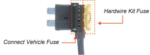 3. Locate the input cable and connect the fuse tap cable to the red input connector. Ensure connection is secure.
 4. Insert the fuse tap into the fuse box.
 5. Tuck away any excess red input cable behind the fuse box.
Connecting to ground
1. Locate earth terminal/bolt or any vehicle bolt accessible that is mounted to the chassis of the vehicle or any metal part of the vehicle – located near the vehicle fuse box.2. Feed black input wire eyelet into bolt and screw bolt back on existing location.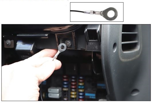 3. Tuck away any excess input cable behind the fuse box. NOTE: The black earth cable needs to be connected to the vehicle chassis otherwise it will not earth out.
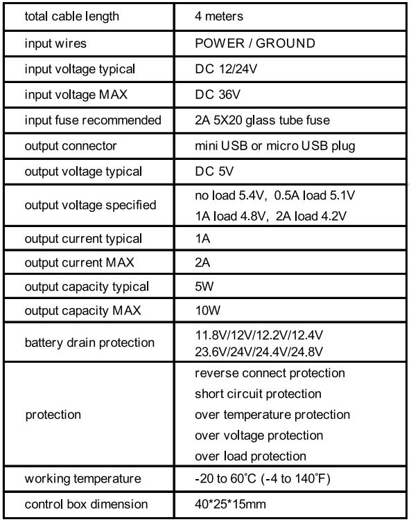
Product specifications
Installation advice
Installation of the GUNIHWC is recommended to be performed by a technician or professional installer. Working with your vehicle’s power system can be dangerous to both you and your vehicle if you do not know what you are doing. If you have any doubts please consult a professional.
IMPORTANT: Refer to your Dash Cam owner’s manual for the initial installation of your dashcam in your vehicle.
The GUNIHWC is a kit that allows for the provision of constant power from your vehicle battery to your Dash Cam. Any issues with your dashcam should be referred to your Dash Cam’s manufacturer.
NOTES————————————————————————————————————————————————————————————————————————————————————————————————————————————————————————————————————————————————————————————————————————————————————————————————————————————————————————————————
Technical assistance
If you need assistance setting-up or using your Gator product now or in the future, call Gator Support.
AustraliaTEL: 03 8587 8898![]() FAX: 03 8587 8866Mon-Fri 9am 5pm AEST
FAX: 03 8587 8866Mon-Fri 9am 5pm AEST
Please retain this user guide for future reference.
If you would like to download a digital copy of this manual, or other Gator manuals/software, please visit the http://gatordriverassist.com website and click on `Firmware & Manuals” for information on where to find the manuals/software.
This manual is considered correct at the time of printing but is subject to change. For the latest manuals and updates refer to the website.
Copyright © 2017 by TDJ Australia All rights reserved. No part of this publication may be reproduced, distributed, or transmitted in any form or by any means, including photocopying, recording, copying, or other electronic or mechanical methods, without the prior written permission of the author.
References
[xyz-ips snippet=”download-snippet”]