
GE GUD27ESSM/27GSSM Unitized Spacemaker Stainless Steel Washer and Dryer

DIMENSIONS AND INSTALLATION INFORMATION (IN INCHES)
Installation Instructions
27″ NOMINAL PRODUCT DIMENSIONS
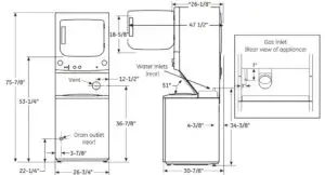
Dimension represents door closed including handle and knobs.NOTE: With feet set at mid position, feet can be adjusted +/- 3/8″.
ELECTRICAL REQUIREMENTS:
GUD27ESSM Electric Dryer – This appliance should be connected to an individual, properly-grounded branch circuit with 120/240V or 120/208V single-phase 60 Hz electrical service and should be protected by 30-amp time-delay fuses or circuit breakers KW Rating per voltage (240/208). This appliance is manufactured with neutral connected to the frame. Power cord should be purchased separately.
GAS REQUIREMENTS:
GUD27GSSM Gas Dryer – This appliance should be connected to an individual branch circuit with 120-volt single-phase 60 Hz electrical service and should be protected by 20-amp time-day fuses or circuit breakers. This appliance is equipped with a 4-foot long flexible U.S. listed 20-amp power cord to match a 20-amp receptacle.
NOTE: Gas Rated input 20,000 BTU/HR. Factory equipped for natural gas. Tested for LP gas. LP gas supply requires a conversion kit. Have a qualified gas technician install a conversion kit before use. Dryers must be exhausted to the outside.
INSTALLATION INFORMATION: For complete information, seeinstallation instructions packed with the product.
For complete information, see installation instructions packed with your dryer.
DUCTING MATERIALS:
For best performance, this dryer should be vented with 4″ diameter all rigid metal exhaust duct. If rigid metal duct cannot be used, then UL-listed flexible metal (semi-rigid) ducting can be used (Kit WX08X10077). In special installations, it may be necessary to connect the dryer to the house vent using a flexible metal (foil-type) duct. A UL-listed flexible metal (foil-type) duct may be used ONLY in installations where rigid metal or flexible metal (semirigid) ducting cannot be used AND where a 4″ diameter can be maintained throughout the entire length of the transition duct. Please see installation instruction packed with your dryer for complete instructions when using flexible metal (foil type) ducting.
EXHAUST LENGTH CALCULATION:
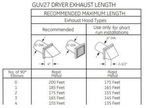
- Determine the number of 90° turns needed for your installation. If you exhaust to the side or bottom of dryer, add one turn.
- The maximum length of 4″ rigid (aluminum or galvanized) duct which can be tolerated is shown in the table.
For every extra 90° elbow, reduce the allowable vent system length by 10 ft. Two 45° elbows will be treated like one 90° elbow. For the side exhaust installations, add one 90° elbow to the chart. The total vent system length includes all the straight portions and elbows of the system (transition duct included).. Dryers must be exhausted to the outside.
CAUTION: For personal safety do not terminate exhaust into a chimney, under any enclosed house floor (crawl space), or into an attic, since the accumulated lint could create a fire hazard or moisture could cause damage. Never terminate the exhaust into a common duct or plenum with a kitchen exhaust, since the combination of lint and grease could create a fire hazard.
Exhaust ducts should be terminated in a dampered wall cap to prevent back drafts, bird nesting, etc. The wall cap must also be located at least 12″ above the ground or any other obstruction with the opening pointed down.
Special Installation Requirements
ALCOVE OR CLOSET INSTALLATION:
- If your dryer is approved for installation in an alcove or closet, it willbe stated on a label on the dryer back.
- The dryer MUST be exhausted to the outside.
- Minimum clearances between dryer cabinet and adjacent walls or other surfaces are: 0″ both sides and rear, 1″ front and top
- Minimum vertical space from floor to overhead cabinets, ceilings, etc. is 76-1/2″.
- Closet doors must be louvered or otherwise ventilated and must contain a minimum of 60 sq. in. of open area equally distributed. If this closet contains both a washer and a dryer, doors must contain a minimum of 120 sq. in. of open area equally distributed.
- No other fuel-burning appliance shall be installed in the same close with a gas dryer.
BATHROOM OR BEDROOM INSTALLATION:
- The dryer MUST be exhausted to the outdoors.
- The installation must conform with the local codes, or in the absence of local codes, with the National Electric Code and National Fuel Gas Code, ANSI Z223 for gas dryers.
MINIMUM CLEARANCES OTHER THAN ALCOVE OR CLOSETINSTALLATION:
- Minimum clearances to combustible surfaces:0″ both sides and rear1″ front and top
FEATURES AND BENEFITS
- Rotary-electromagnetically controls (dryer) – Allow fast, easy cycle selection
- 11 wash cycles – Cycles are designed to specifically handle various fabrics and soils
- 6 wash/rinse temperatures – Select the right temperature for ideal wash results
- 1 wash/spin speed combinations – Speeds are matched to fabric type for great clothes care
- Auto-load sensing with 4 water levels – Washer will automatically measure theload size and add just the right amount of water
- Rotary-electronic controls (washer) – Simplify cycle selection
- Bleach and fabric softener dispensers – Solutions are automatically mixed with wash water for clean, bright, soft-to-the-touch results
- Cycle status lights – Easily see where your load is in the cleaning process
- Model GUD27ESSMWW – White on white (Electric)
- Model GUD27GSSMWW – White on white (Gas)
For answers to your Monogram, GE Café™ Series, GE Profile™ Series or GE Appliances product questions, visit our website at geappliances.com or call GE Answer Center® Service, 800.626.2000.
Read More About This User Manuals…
Questions about your Manual? Post in the comments!
[xyz-ips snippet=”download-snippet”]