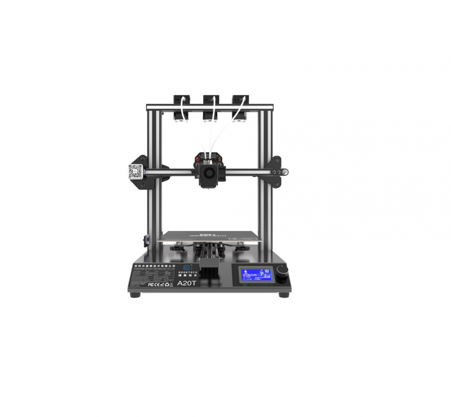
Geeetech A20T 3D Printer V1.00
 [Important] Please read the instruction manual carefully before using this machine.
Attention
Safety instructions
- Please switch to the correct local voltage (110V-220V) before turning on the printer. Be sure the switch is in the correct position or it will damage the power supply unit (PSU).

- Be sure all wires are correctly connected before turning on the printer.
- Don’t touch the extruder head or hot bed when printing as they generate high temperature which may cause burn.
- Don’t leave the printer unattended when printing.
Factory test before delivery
In order to ensure the quality, each printer is tested in the factory before delivery. As a result, there may be residue in the extruder head or on the hot bed, but it should not affect normal use. We provide the spare nozzle in the accessory kit just in case.
Risk statement
- Before color is mixing or monochrome printing, make sure that there is the filament in the feeding tube on both sides of the extruder head to prevent back flushing of the molten filament inside the extruder head, resulting in clogging.
- Make sure there is filament in feeding tubes on the both side of extruder head even using a single-sided extruder for monochrome printing, moreover the filament in the other feeding tube cannot be pulled out during the printing process.
- Please do not disassemble the printer without permission. If there is any problem, please contact the after-sales service.
Parameters
- Printing parametersPrinting technology: FDMPrinting volume: 250*250*250mm3Printing accuracy: 0.1~0.2mmPositioning precision: X/Y: 0.011mm Z: 0.0025mmPrinting speed: 60mm/sNozzle quantity: 3-in-1-out single nozzleNozzle diameter: 0.4mmFilament: Diameter 1.75mm; ABS/ PLA, etcEnvironment temperature: 10℃-40℃Operating system: Windows/Mac/LinuxSlicing software: Repetier-Host, EasyPrint 3D, CuraFile format: .STL/.Gcode
- Electrical parametersPower input: 100-120V/200-240VPower output: DC24V/14.6A,350WConnectivity: TF card, USBLCD screen: LCD 12864 screen
- Mechanical parametersPrinter size: 442x447x480 mm3Package size: 510x495x305 mm3Net weight: ~9kgGross weight: ~11.5kg
Packing list
Please check the parts/accessories when you receive the printer (As shown below). If any spare parts are missing, please contact your sales representative.
 |
 |
|
|
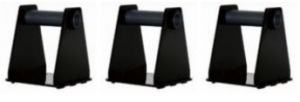
Gantry kit |
Bottom kit |
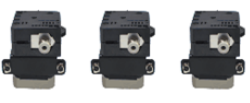
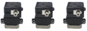
Extruder motors (3 sets) |
 |
 |
 |
|
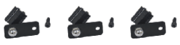
Filament detector kit (3 sets) |
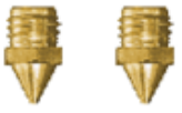
Nozzles *2 |
Filament holder kit(3 sets) |
 |
|
 |
|
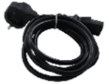
Power cord |
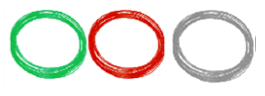
Filaments(3 random colors ) |
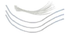
Teflon tube & Zip ties |
 |
 |
 |
|
TF Card |
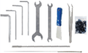
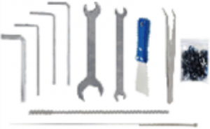
Tool kit |
Mouse pad |
 |
 |
 |
|
USB cable |
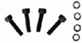
Machine installing screws |
User guide |
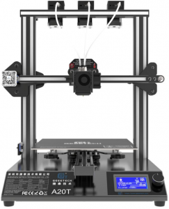
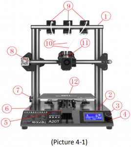
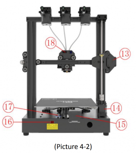
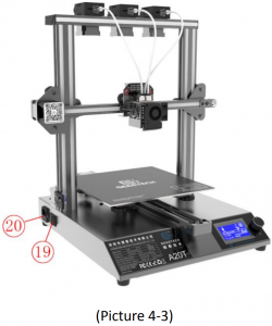
Machine Overview
- Gantry frame
- LCD12864 screen
- Knob
- Reset button
- Y axis
- Bottom kit
- Z axis end stop
- X axis end stop
- Extruder motors (3 sets)
- Teflon tube
- Extruder head
- Hot bed
- X axis motor
- Z axis motor
- Y axis motor
- Power voltage selector switch
- Y axis end stop
- Extruder wire interface
- Power switch
- Power socket
- USB port
- TF card slot

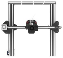
Assembling
The main frame consists of the gantry kit and the bottom kit, extruders, filament holder, and screws. See table down below.
 |
 |
|
|
Gantry kit |
Bottom kit |
Extruder motors (3 sets) |
|
 |
 |
|
Filament detector kit (3 sets) |
Machine installing screws |
Tool kit |
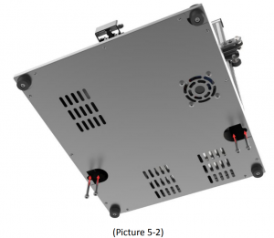
- Assemble the gantry frame and base from bottom to top with 4 M5x35screws and 4 M5 spring washers. See picture (5-2)
- Assemble and fix the three sets of extruder units to the back side of the top gantry as shown
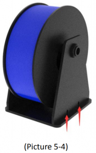
- Filament holder kit was assembled as shown in Picture (5-4) with 4 M3x16 screws, 4 M3 nuts and 4 M3 washers, a total of 3 sets were assembled. Wire connection.

Wire connection
- Insert the three Teflon tubes into the quick-insert connector of the three extruders respectively. It can be inserted into the quick- insert connectors of E0, E1 and E2 as needed. Details see picture (5-5)
- Plug the extruder cables into the socket of the extruder head adapter plate, and the buckle must be fastened. See picture (5-6)
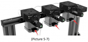
- Connect the motor wires of E0、E1and E2. See picture (5-7).
- Then the extruder wire and the motor extruder wire are fixed into the small hole on the backside of the screw with the Cable tie to avoid the wire harness touching the model during printing. In addition, the position the harness s touching the model during printing. In addition, the position the harness fixed needs to reserve the length of the Z-axis at the maximum height. See picture (5-8).
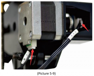
- Connect the wires of X axis’ motor and end stop. See picture (5-9).
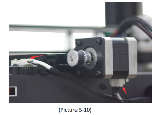
- Connect the wires of Y axis’ motor and end stop. See picture (5-10).
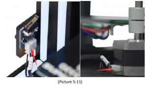
- Connect the wires of Z axis’ motor and end stop. See picture (5-11)


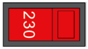
Check the power input mode
The factory default voltage is 230V. You need to choose the correct voltage according to your local standard requirement. See picture (5-12)Note: Be sure the voltage is switched to the correct one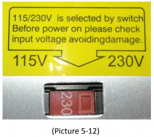
Check the filament
Put the filament on the spool holder. Please pay attention to the feeding direction of the filament. See picture (5-13).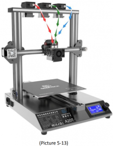
Since the filament is bent, the first section of it needs to be straightened by hand and trimmed to make it easier to insert the filament into the feeder. Press down the lever handle of the extruder and insert the filament into the feeding tube until it reaches the extruder head. See picture (5-14).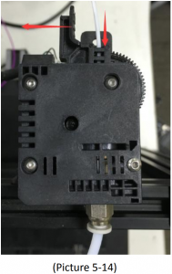
When print PLA, set the target nozzle temperature about (190~210℃). When the temp is stable, control the extruder filament feeding on LCD screen (“Move axis”), feed until there is molten material flowing from the nozzle.
Observe the nozzle, if there is no filament stuck and the filament is coming out smoothly, then stop filament feeding, clear the nozzle with tweezers. See picture (5-15).

First print
Level the print bed
The first layer is basis to a successfully printed model. The factory default setting is a little high in order to avoid scratching the hotbed with the nozzle, so users need to adjust the distance between nozzle and hotbed again. After the first-time bed leveling, users don’t need to level the bed again.
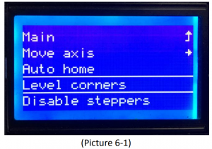
- Rough levelingHome the printer first (“Prepare”> “Auto home”), then it shows the option “Level corners” on the LCD screen. Put a piece of A4 paper on the platform, click “Next corner”, the extruder head moves counterclockwise from the bottom left corner to the four corners of the platform. See picture (6-1, and 6-2).When the extruder head moves to the left bottom, adjust the corresponding knob until the distance between the nozzle and bed is about the thickness of a piece of paper (about 0.1-0.2mm). Slide the paper back and forth to see if you feel a slight resistance. If yes, it means the leveling of this corner is finished and you can proceed to level the rest corners with the same method. See picture (6-3).
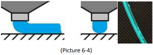
- Accurate levelingIf you level the bed with A4 paper, the first layer maybe too high, too low or moderate.a. Too high: the distance between the nozzle and bed is too far, which may cause the filament to not stick or not stick well. See picture (6-4).b. Too low: the distance between the nozzle and the bed is too close, which prevents the filament from coming out and causes the extruder gear to click, and even worse, scratch the nozzle on the bed. See picture (6-5).c. Moderate: Extrude the filament properly and evenly stick on the bed. See picture (6-6)In the case of too low and too high, adjust the knobs under the platform till they are moderate. It may take some trial and error to achieve the best result. An example of good first layer, see picture (6-7).Note:
- If turn the knobs clockwise, the platform will rise, and vice versa.
- Avoid the nozzle touching the bed; use a piece of A4 paper. Or it will scratch the bed.For more details, please refer to this link: http://geeetech.com/forum/viewtopic.php?f=112&t=62296
 When the extruder head moves to the left bottom, adjust the corresponding knob until the distance between the nozzle and bed is about the thickness of a piece of paper (about 0.1-0.2mm). Slide the paper back and forth to see if you feel a slight resistance. If yes, it means the leveling of this corner is finished and you can proceed to level the rest corners with the same method. See picture (6-3).
 b. Too low: the distance between the nozzle and the bed is too close, which prevents the filament from coming out and causes the extruder gear to click, and even worse, scratch the nozzle on the bed. See picture (6-5).
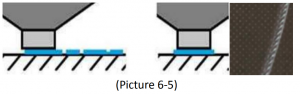 c. Moderate: Extrude the filament properly and evenly stick on the bed. See picture (6-6)
 In the case of too low and too high, adjust the knobs under the platform till they are moderate. It may take some trial and error to achieve the best result. An example of good first layer, see picture (6-7).
 Note:
Note:TF card printing
Insert the TF card into the slot. See picture (6-8)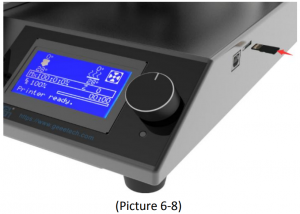
Press and rotate the knob to enter the main menu. Select the option of “Print from SD”. See picture (6-9).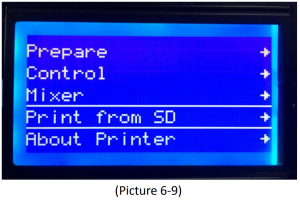
Choose the files in the TF card. See picture (6-10).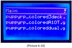
The printer will heat automatically. See picture (6-11).
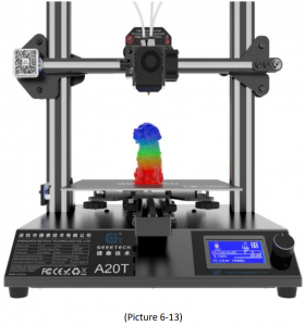
When heating done, the printer will start printing until the print is complete. See picture (6-12, 6-13).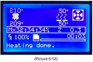
Tree diagram

Main functions
LCD rotating knob:
- Press the knob: Confirm or enter the next menu.
- Rotate the knob: Roll the select options or change parameters.
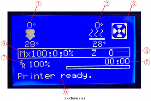
LCD homepage, see picture (7-2):
- Extruder temperature: Current temp/target temp
- Hot bed temperature: Current temp/target temp
- Extruder head blower status
- Current Z axis value
- Printing process
- Current printing info
- Feed rate: Current printing speed
- Mix-color printing ratio: E0; E1; E2%
Note: Rotating the knob can change the printing feed rate during printing. We suggest users not changing the feed rate too much or it will make the motors to skip caused by too fast speed and affect the print quality.
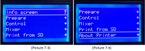
Press the knob to enter the next menu (Picture 7-3, 7-4):
- Prepare: Prepare and test the printer before normal operation
- Control: Printer temp and motion parameter setting
- Mixer: Mix-color ratio setting
- Print from SD: TF/SD card printing
- About Printer: The printer info
The main functions of Prepare menu (Picture 7-5, 7-6):
- Move axis: Move X/Y/Z axis and Extruder
- Auto home: X/Y/Z axis auto homing
- Disable steppers: Unlock motors
- Change filament: Change filament
- Preheat PLA: Manually pre-heat the hot bed and extruder before printing PLA.
- Preheat ABS: Manually pre-heat the hot bed and extruder before printing ABS.

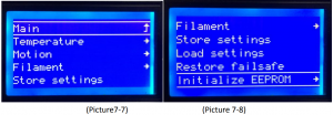
The main functions of Control menu (Picture 7-7, 7-8):
- Temperature: Change the temp of the hot bed and extruder in real time during printing. Customize the temp of preheat PLA and preheat ABS.
- Motion: Motion parameter setting in firmware. After modification, choose “store memory” to save the change.
- Filament: Open or close filament detector; set filament diameter.
- Store settings: Save the parameters modified.
- Load settings: If you need to restore to the original settings, please choose this option.
- Restore failsafe: Restore factory setting.
- Initialize EEPROM: Initialize printer Settings
The main functions of Mixer menu:
Mx: Fixed mix ratio print mode, as shown in Picture (7-9). Mx∧ : The blend ratio printing mode changes with height, as shown in Picture (7-10).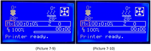 Mixer menu offers two mix-printing options, namely fixed mix ratio printing and and Mix ratio printing mode that varies with height. The detailed operation steps for your reference:
Set fixed mix ratio
Choose “Mixer” and press the knob. Rotate the knob to choose “Mix: 100; 0; 0%”. Adjust the mix ratio and press the knob to confirm. See picture (7-11, 7-12, and 7-13).
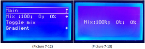 “Toggle mix”: If you need to quickly switch the ratio between E0; E1and E2, you can select this function to switch, see picture (7-14)
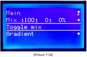
Set the mix ratio print mode that varies with heightFirst, you need to get the current z-axis coordinate, which can be found on the screen, details see picture (7-15).
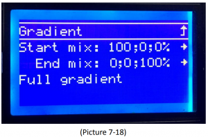
Choose “Gradient” to set the variable mix ratio, details see picture (7-16)
“Gradient mix”: Adjust the filament ratio of E0 、E1and E2. See picture (7 17and 7-18).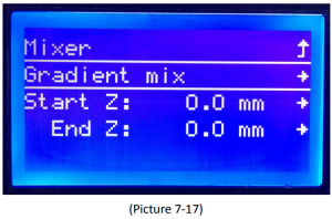
“start Z”: The starting position (z-axis height) of automatic change of mixing; automatically change the mix based on the current Z height obtained in the previous step.“end Z”: The end of automatic change of mixing (z-axis height).Choose “start z” and “end z”, press and rotate the knob to set the starting and ending position of mixing. Then select the model to print, the machine will automatically print according to the ratio of the mixture just set, the above is the main function of the mixer menu. See picture (7-19).
Test the motors’ function via LCDPress the knob to enter the next menu; choose “Prepare”. See picture (7-20).
Choose “Auto home” to home the printer, see picture (7-21).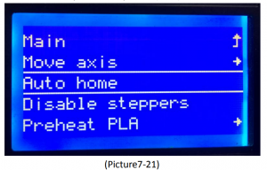
Choose “Move axis” to move motors. See picture (7-22)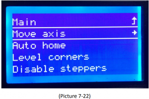
Choose from “Move X/Y/Z/Extruder” and rotate the knob to move them. See picture (7-23).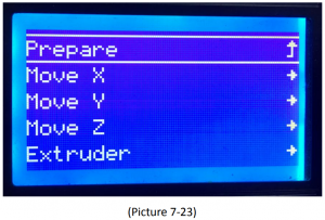
Choose “Move 1mm”, see picture (7-24).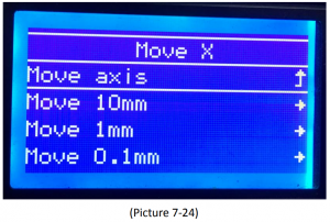
Note: we suggest using 1mm to test X/Y/Z axis.
After axis’ testing finished, if you want to unlock the motor, choose “Prepare>Disable steppers”, see picture (7-25).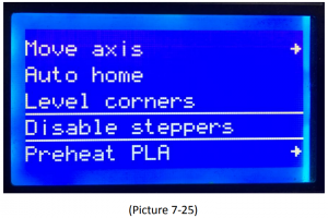 When the motors are unlocked, you can move them by hand.
Software setting
Install driver
Two printing choices for A20T: TF card printing and USB printing.TF card printing: After leveling, insert the TF card into the slot, and choose a .gcode file to start printing.USB printing: Connect the printer and computer with a USB cable to control the printer with slicing software such as Repetier-Host. Because of some unstable factors such as signal interference, the USB printing prone to fail. So we suggest choosing TF card printing.The details of USB printing are as follows:Firstly, turn on the printer, and connect the printer to computer with a USB cable. Normally, the computer will automatically search the install driver. The newest communication chip of A20T is CH340. See picture (8-1).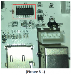
If it fails to automatically install the driver in computer, then check whether the driver is installed successfully or not. Click to choose “My computer>Property>Device manager”. If it shows the exclamation mark as picture below (8-2), then you need manually install the driver.
Download link for CH340:https://www.geeetech.com/index.phpmain_page=download&download_id=40After the driver is installed, check the “Device manager” and see if it is same as the picture below (8-3). If so, it means the driver is successfully installed.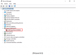
Install slicing software
Repetier-Host is the default slicing software here. Download address: https://www.repetier.com/download-software/
- Set printer parameters
When Repetier-Host is installed, turn on the printer and open the Repetier Host. Repetier-Host supports several languages. You can choose your native language from Config>Language (Picture 8-4 for details).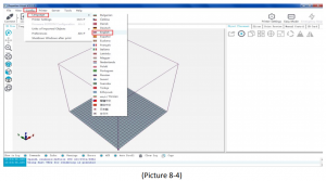
English interface for your reference (picture 8-5).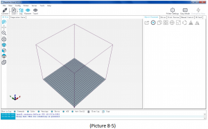
Using the Repetier-Host for the first time, printer parameters need to be configured before connecting. Click “Printer settings” on the top right corner, see picture (8-6).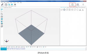
The following window pops up, and you can fill in according to the contents of the label. (Pay attention to the highlighted parts)a. Connection dialog: see picture (8-7)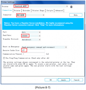
b. Printer dialog (Picture 8-8):Do not check “Return to the parking position after the end of the task interruption” to prevent the machine from damaging the model after the end of printing.
c. Extruder dialog (Picture 8-9):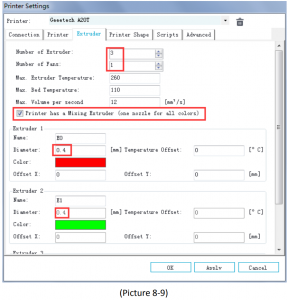
d. Printer shape dialog (Picture 8-10):
Now the printer parameters are set.Note: If the operating system is Mac OS, Repetier Host baud rate is also set to 250,000.
- Set slicing parameters
After setting the printer parameters, click “Connect” on the top left corner. The color of the icon changed to green means the printer connects to the Repetier-Host successfully. Click it again to disconnect. See picture (8-11).
After successfully connected, choose “Slicer> CuraEngine” and open the configuration menu. See picture (8-12).
It pops up dialog as picture below (8-13):
Printer parameters are important to print quality. Customers need to run tests to find the best parameters for their printers. Here we provide a configuration file for your reference (“Geeetech A20T PLA high.rcp”). You can import it according to the steps as follows, this file can be downloaded from the official website. The following is an example of parameters for PLA (Picture 8-14):Click “Print>Import”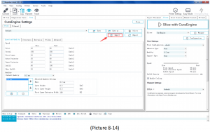
It pops up the dialog as below (Picture 8-15). Choose “Geeetech A20T PLA high.rcp” and open it.
Now, the configuration file is imported, click “Save”. See picture (8-16).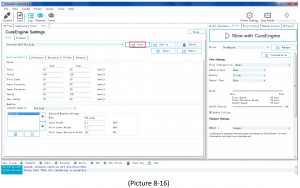
Click “Filament>Import”, see picture (8-17).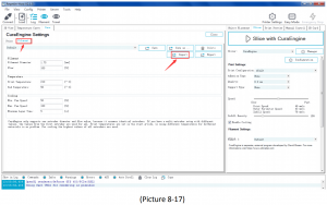
It pops up dialog as below (Picture 8-18); choose “Geeetech A20T PLA high fi.rcf”
Now, the configuration file is imported. Click “Save”. See picture (8-19)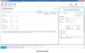
Choose “Geeetech A20T PLA high” as print configuration and “Geeetech A20T PLA high fi” as printing material setting. Details see picture (8-20) below.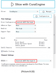 Now parameters setting are finished.
USB printing
You can start USB printing when the parameters setting are finished.The model file format is .stl for 3D printer. You can download free models from websites such as thingiverse.com You can also design your own models.
- Load the printing model
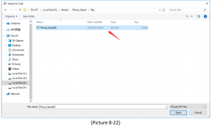
Open the Repetier-Host and click “load”. Choose a file and open it. See picture (8-21, 8-22).
When it is loaded, you can use the buttons as picture below (picture 8-23) to zoom in, zoom out or rotate the model.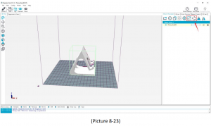
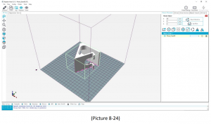
Adjust the direction of the model so that the flat part of the model is touching the hot bed. See picture below (8-24):
Note: If the model loaded is too big and beyond the printing platform, you need to zoom out the model. Click to “zoom the object”. You can perform a uniform scaling as shown in Picture (8-25).
Or zoom in/out them separately, see picture (8-26)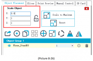
- Model slicing
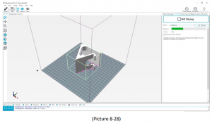
After setting the model size and direction, select the previously imported slice parameter settings in the slice software window, and then click “Slice with CuraEngine”. See picture (8-27), (8-28).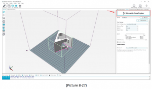
You can find the model information such as estimated print time, the amount of filament needed, etc. Click “Print” to start USB printing. Refer to picture (8-29).The printer will heat to the target temp and then start printing. Under high temperature, the filament will flow out of the nozzle, which is normal. You can use tweezers to clean up the residual material of the nozzle.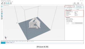
TF card printing
When all parameters are set, click “Save for SD print”. It will pop up a dialog as picture below (See picture 8-30) and then click the save button to generate a .gcode file. Copy the gcode file to the TF card.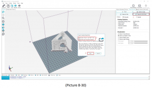
Insert the TF card into the TF card slot on the right side of the machine. Press the knob to enter the main menu and choose “Print from SD”. See picture (8-31).Choose the corresponding gcode file to start printing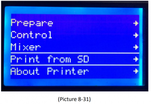
Note:
- The printer can only read gcode file and the file name should be English letters, a space, an underscore or their combination.
- The Gcode file cannot be placed in any folder of the TF card, otherwise it cannot be read.
Color Mixer
Download
Download address: http://www.geeetech.com/forum/viewtopic.php?f=92&t=61760
Introduction
Color Mixer enables multicolor models to be printed by adjusting the extruder discharge ratio to the original single-color model. The specific steps are as follows:
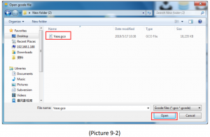
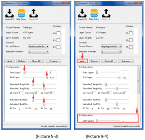
- Click “Import G” to import .Gco file. Choose 3 as the “Extruder Number”. See picture (9-1 and 9-2)
- After importing the .Gco file, you can set the height of start and end layer, and the discharge change percentage of extruders according to actual needs. You can adjust by dragging the slider or entering a value. See picture (9-3).
- In addition, you can click “Add” to add multiple configuration boxes to adjust the extruder discharge change ratio at different starting and ending heights. As shown in picture (9-4).
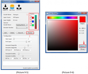
- See picture (9-5), Adjust discharge change ratio of each extruder in a range of heights as needed, click the E0, E1, E2 button in the “Preview” window in the upper right corner to enter the color selection interface, as shown in Picture (9-6). The color here should be selected according to the actual filament color of each extruder, and then click “Select” to confirm. After selecting corresponding color to each extruder, click the “Preview” button below to display color change of the current configuration in the box on the right side of the small window.
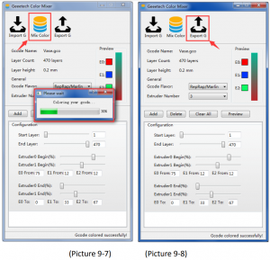
- After configuring the parameters, click the “Mix Color” button to change the original single-color model to a custom multicolor model. As shown in Picture (9 7).
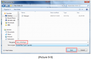
- Click “Export G” to export and save the mixed color model, which is named with a suffix “_colored”. Copy the file to the TF card and insert it into the machine to start printing. See picture (9-8, and 9-9). The processed model is shown in picture (9-10).


Function introduction
Power loss-resuming capability
A20T has the power loss-resuming capability. When power recovery starts, it will pop up a dialog to ask if continuing the unfinished print caused by power outage, choose “Resume print”. See picture (10-1).
When it reaches the target temperature, the X and Y axes will auto home. The extruder will extrude the residue in the nozzle. Use a tweezers to clean the nozzle before starting printing again.
Note:
- When power outage, move the nozzle away from the printing model in case the filament oozes out on to the print.
- Be sure to clean the residue in the nozzle before restarting the print or it would affect the quality of the print.
The reset button is below the knob. When the printer works abnormally, press the reset button to reset the printer to avoid any damage. See picture (10-2).
Filament run-out sensor (Optional)
Before using this function, please check whether it is turned on or not. Choose “Control”>”Filament”>“Runout sensors” and make sure it shows “ON”. See pictures (10-3, 10-4).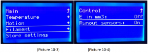
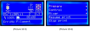
- It will pop up the notification “Err: No Filament” when the filament is run out during printing and the printer will stop. See picture (10-5).
- Press the extruder handle, remove the remaining filament before loading the new filament.
- When the filament is loaded, use a tweezers to clean the nozzle. Press the knob to enter the main menu, and choose “Resume print” to re-start the printing. See picture (10-6)
3D touch for auto bed leveling (Optional)
This printer supports auto bed leveling. Refer to the link below to know how to install the 3d touch sensor.
https://www.youtube.com/watch?v=_RtsZDbR2po&t=66sVisit our official forumhttp://www.geeetech.com/forum/
FAQ (Frequently Asked Questions)
Abnormal extrusion
- The filament is tangled
- The nozzle temp is too low to reach the melting temperature required.
- There is carbonized residue inside the nozzle. Please replace it with the spare nozzle
- Insufficient heat dissipation of radiator of the extruder head causes the filament in the tube to melt in advance and the extrusion strength is insufficient. Please check whether the cooling fan works normally.
- The printing speed is so fast that the extruding speed can’t match it. Please reduce the printing speed
The gear of the extruder skips and makes an abnormal noise
- The nozzle is clogged; please refer to 1 abnormal extrusion.
- Check whether the friction force between the extruder gear and the filament is enough. Please clean the residue.
- Check whether the voltage of the driver of the extruder is normal, and try to increase it by 1v until it works normally, max 1.2v.
First layer abnormal
- Non-stick: a. the nozzle is too far from the hot bed. Please re-level the bed, try to stick masking paper or glue stick on the surface of the hot
- Not extruding and the bed scratched: a. the nozzle is too close from the hot bed. Please re-level the bed; b. check if the nozzle extrusion normal
Layer shift
- The printing speed is too Please slow it down.
- The belt of X or Y axis is too Please tighten it.
- The X or Y axis synchronization wheel is not fixed Please adjust the eccentric nuts.
- The voltage of the driver of X/Y axis is too low
Print stopped
- USB printing: the signal is Please copy the model to TF card and print via TF card.
- TF card printing: the gcode file in the TF card is abnormal, please slice
- The quality of the TF card is Please try another TF card.
- The power supply voltage in the area is not stable; please print after the voltage is
Visit our official forum for more information: http://www.geeetech.com/forum/viewtopic.php?f=98&t=61864
Declaration
Terms
Please be advised of the following terms (the “Terms”) regarding this User Manual (this “Manual”):All information in this Manual is subject to change at any time without notice and is provided for convenience purposes only. Geeetech reserves the right to modify or revise this Manual in its sole discretion and at any time. You agree to be bound by any modifications and/or revisions. Contact the Geeetech Support Team for up-to-date information.
Disclaimers
Neither Geeetech nor any of our affiliates warrants the accuracy or completeness of the information, products, or services provided by or through this Manual, which are provided “as is” and without any express or implied warranties of any kind, including warranties of merchant ability, fitness for a particular purpose, or non-infringement of intellectual property. To the fullest extent permissible by the applicable law, we hereby disclaim all liability for product defect or failure or for claims that are due to normal wear, product misuse or abuse, product modification, improper product selection, noncompliance with any codes, or misappropriation. To the fullest extent permissible by the applicable law, we hereby disclaim any and all responsibility, risk, liability, and damages arising out of death or personal injury resulting from assembly or operation of our products. Geeetech assumes no responsibility, nor will be liable, for any damages to, or any viruses or malware that may infect your computer, telecommunication equipment, or other property caused by or arising from your downloading of any information or materials related to Geeetech products.
SHENZHEN GETECH TECHNOLOGY CO., LTD

Geeetech A20T 3D Printer V1.00 Users Manual – Geeetech A20T 3D Printer V1.00 Users Manual –
[xyz-ips snippet=”download-snippet”]