
Empower Your Sound![]()
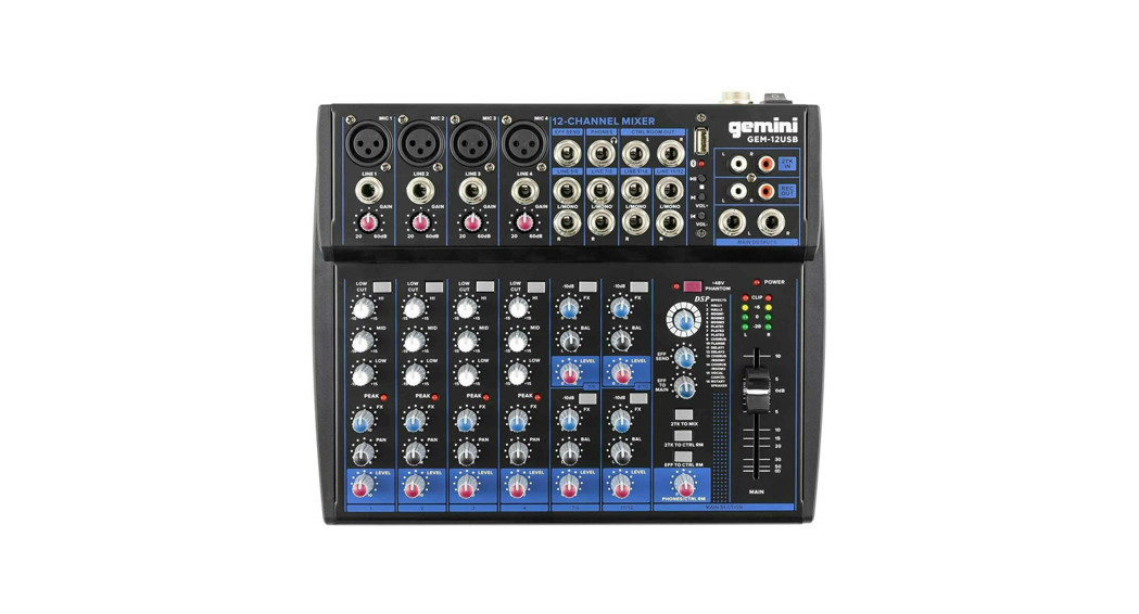
GEM-12USBPortable Mixing Console
Introduction
Congratulations! With the GEM-12USB you have purchased a state-of-the-art mixing console that sets new standards. Our prime goal when developing the mixer was to design a console that can be used for a great variety of applications. And to give you maximum flexibility. In combination with its comprehensive range of features and pro-level connections, the mixer will be your perfect tool for any kind of application: broadcasting, video dubbing, or mixing a live band.
Before You Begin
Your mixer was carefully packed and the packaging is designed to protect the unit from rough handling. Nevertheless, we recommend that you carefully examine the packaging and its contents for any signs of physical damage, which may have occurred during transit.Be sure that there is enough space around the unit for cooling and please do not place the mixer on any hot surface.
Control Elements
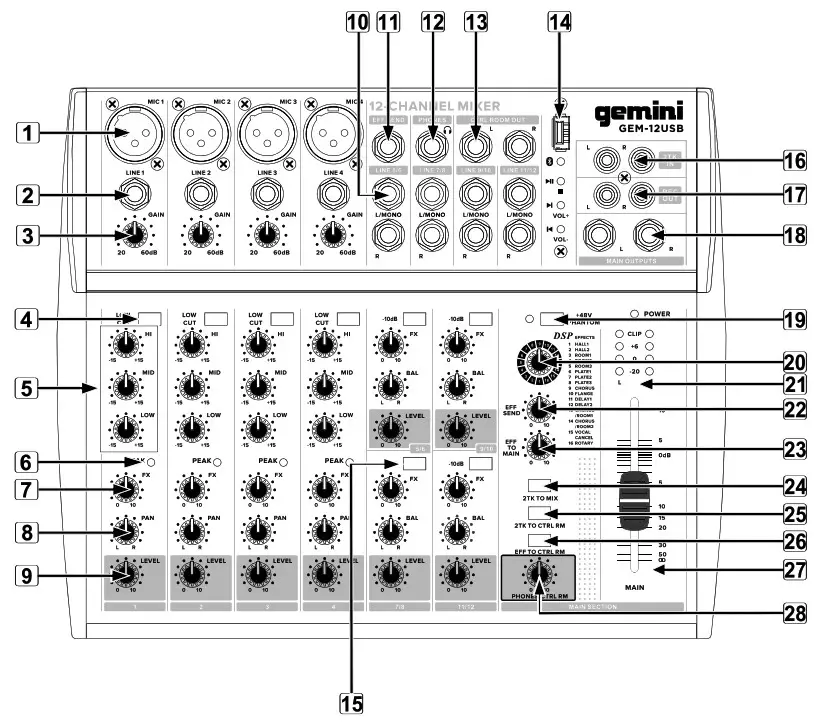
- MIC Use this balanced XLR jack to connect a microphone to the mixer.♦ The phantom power required for condenser mics can be activated with “+48V PHANTOM” switch.
- Channels 1-3 feature an additional line input on a balanced 1/4″jack.
- Use the GAIN control to adjust the input gain. This control should always be turned fully counterclockwise whenever you connect or disconnect a signal source to one of the inputs.
- In addition, the mono channels are equipped with a steep LOW CUT filter (slope at 18 dB/oct, -3 dB at 75 Hz) designed to eliminate unwanted low-frequency signal components.
- The upper (HIGH) and the lower band (LOW) are shelving filters that increase or decrease all frequencies above or below their cut-off frequency. The cut-off frequencies of the upper and lower band are 12 kHz and 80 Hz respectively. The MID band is configured as a peak filter with a center Frequency of 2.5 kHz.
- The PK LED’s of the mono channels illuminate when the input signal is driven too high, which could cause distortion. If this happens, use the GAIN control to reduce the preamp level until the LED does not light anymore.
- EFF sends enable you to feed signals via a variable control from one or more channels and sum these signals to a bus. The bus appears at the console’s EFF sent to output and can be fed from there to an external effects device. The return from the effects unit is then brought back into the console on the stereo channels. Each EFF send is mono and features up to +10 dB gain.
- The PAN control determines the position of the channel signal within the stereo image. Turning PAN knob left will send Audio to the left side of MASTER output and vice versa. 9 ‘IO.
- The LEVEL control determines the level of the channel signal in the main mix.
- LINE IN Each stereo channel has two balanced line-level inputs on 1/4” jacks for left (L/MONO) and right (R) channels. If you use only the (L/MONO) jack, same sound is output from both Left and right speakers.
- The EFF SEND connector outputs the signal you picked up from the individual channels using the EFF SEND controls. You can connect this to the input of an external effects device in order to process the EFF bus’ master signal. Once an effects mix is created, the processed signal can then be routed from the effects device outputs back into a stereo input.
- PHONES/CTRL ROOM OUT The stereo PHONES connector (at the top of the connector panel) is where headphones are connected.
- The unbalanced CTRL ROOM OUT connectors carry the summed effects and main mix signals as well as soloed channel signals. The PHONES/CONTROL ROOM control in the main section adjusts the level Of both headphones and main monitor outputs. The unbalanced CTRL ROOM OUT jacks carry the summed effects and main mix signals, The PHONES/CTRL RM control adjusts the level of both headphones and CTRL ROOM OUT.
- USB JackPlay/Pause Long press this key until the indicator flashes. Then turn on your device’s bluetooth, search until the bluetooth link of the mixer, appears and select to connect device.Vol+/Next Press once to skip to next song. Press and hold for volume up.Vol-/Prev Press once to song skip to prev song. Press and hold for volume down.
- The -10dB switch will pad the input by -10 dB. Activate if line signal is coming in too hot.
- 2TK RET The 2-TRACK INPUTS are used to bring an external signal source (e.g. CD player.tape deck, Etc.) into the console.
- REC OUT These connectors are wired in parallel with the MAIN OUT and carry the main mix signal (unbalanced). Connect the 2-TRACK OUTPUT to the inputs of your recording device. The output level is adjusted via the high-precision Main Mix fader. The MAIN OUT connectors are unbalanced mono jacks. The main mix signal appears here at a Level of 0 dBu. The Main Mix fader adjusts the volume of these outputs.
- The red +48V LED lights up when phantom power is on. The PHANTOM switch activates the phantom power supply on the XLR connectors of all mono channels.
- DSP FX selection.
- Level indicator: The high-precision 4-segment display accurately displays the relevant signal level.
- The EFF SEND control adjusts the volume level of the EFF signal provided at connector EFF SEND JACK.
- The EFF TO MAIN control feeds the effects signal into the main mix. If the control is turned all the way counterclockwise, no effects signal is present in the sum signal of the mixing console.
- The EFF TO MAIN control feeds the effects signal into the main mix. If the control is turned all the way counterclockwise, no effects signal is present in the sum signal of the mixing console.
- When the 2TK TO MIX switch is depressed , the 2-track input is assigned to the main mix providing an additional input for tape machines, electornic instruments or other signal sources that do not require any processing.
- Press the 2TK TO CTRL RM switch if you want to monitor the 2-track input via the CTRL ROOM OUT. This provides an easy way to monitor signals coming back from tape to ensure that they are recording correctly.
- If you want to monitor only the effects signal in your headphones or monitor speaker(s), press the EFF TO CTRL switch. Now the signal of the effects processor can be monitored alone, and the main mix and/or CD/ tape signal is no longerpresent on the phone and control room outputs.
- Use the MAIN fader to set the overall volume level of your mixer.
- The PHONES/CTRL RM control adjusts the level of both headphones and CTRL RM outputs.
DSP DIGITAL REVERB EFFECT ENGINE
| Hall 1 | Bright hall reverb for drums. guitars. and vocals. |
| Hall2 | Warm hall for acoustic guitars, pianos, and vocals. |
| Room 1 | Hardwood studio for acoustic instruments. |
| Room 2 | Ambience for acoustic mixes and synth sounds. |
| Room 3 | Warm room for guitars and rhythm instruments. |
| P|ate1 | Classic plate reverb for lead vocals and instruments. |
| Plate 2 | Sizzling bright plate reverb for vocals and drums. |
| Plate 3 | Short vintage plate reverb for snares and guitars. |
| Chorus | Stereo chorus for guitars and pianos. |
| Flange | Stereo flanger forjet wash effects. |
| Delay1 | 125ms slapback delay for vocals and guitars. |
| Delay 2 | 190ms delay for percussive arpeggios. |
| ChoruslRoom1 | Chorus with reverb for guitars, synths, and pianos. |
| ChoruslRoom 2 | Auto-wah guitar effect with reverb for lead instruments |
| Vocal Cancel | Removes lead vocals from many stereo recordings. |
| Rotary Speaker | Rotary speaker emulation for organs and guitars. |
GEM 12USB FRONT & REAR PANEL
SPECIFICATIONS:
- 12 standard inputs
- 4 balanced MIC/LINE inputs
- 3 band frequency equalizer for mono inputs
- 1 phantom power
- 4 stereo input
- 2TK input & REC output
- level LED indicate display
TECHNICAL DATA:Common mode rejectiomi ______________-80dBuS/N Ratio: _________________________ -82dBFrequency response: — +/-O.5dB 2OHz-2OKHzTHDX_____________ lass than <0.03%@1KHzINPUT LEVEL:MIC input: ______________________+60dBuLlNEinput:______________________+30dBstereo input: _____________________+20dBuheadphones output(20O Q )__________300mWarametric EQ:HIGH: _________________________12khZ,+/-15dBLOW: _________________________8OHZ, +/-15dB
SAFETY INSTRUCTIONS
- Read these Instructions.
- Keep these Instructions. 3
- Heed all Warnings.
- Follow all Instructions.
- Do not use this apparatus near water.
- Clean only with dry cloth.
- Do not block any ventilation openings. Install in accordance with the manufacturer’s instructions.
- Do not install near any heat sources such as radiators, heat registers, stoves, or other apparatus (including amplifiers) that produce heat.
- Do not defeat the safety purpose of the polarized plug. A polarized plug has two blades with one wider than the other. The wide blade is provided for your safety. If the provided plug does not fit into your outlet, consult an electrician for replacement of the obsolete outlet.
- Protect the power cord from being walked on or pinched, particularly at plugs, convenience receptacles, and the point where they exit from the apparatus.
- Only use attachments/accessories specified by the manufacturer.
- Use only with the cart, stand, tripod, bracket, or table specified by the manufacturer or sold with the apparatus. When a cart is used, use caution when moving the cart/apparatus combination to avoid injury from tip-over.
- Unplug this apparatus during lightning storms or when unused for long periods of time.
- Refer all servicing to qualified service personnel. Servicing is required when the apparatus has been damaged in any way, such as power-supply cord or plug is damaged, liquid has been spilled or objects have fallen into the apparatus, the apparatus has been exposed to rain or moisture, does not operate normally, or has been dropped.
- WARNING: To reduce the risk of fire or electric shock, do not expose this apparatus to rain or moisture.
- Since the device’s power cable is used as the primary disconnection device, the power cable should remain readily operable at all times.
- The ventilation should not be impeded by covering the ventilation openings with items, such as newspapers, table-cloths, curtains, etc.
- No naked flame sources, such as lighted candles, should be placed on the apparatus.
- The apparatus should be used in moderate climate.
- The apparatus shall not be exposed to dripping or splashing and no objects filled with liquids (such as drinks) shall be placed on the apparatus.
WARNINGTo reduce the risk of electric shock, do not remove cover (or back). There are no user serviceable parts inside. Maintenance and repairs should be exclusively carried out by qualified service personnel.CAUTIONTo reduce the risk of electric shock, do not remove cover. No user serviceable parts inside. Refer servicing to qualified service personnel only.

![]() The warning triangle with exclamation mark indicates important operating and A maintenance instructions.
The warning triangle with exclamation mark indicates important operating and A maintenance instructions.![]() The warning triangle with lightning symbol indicates dangerous uninsulated voltage A inside the unit, which may cause an electrical shock.To prevent electric shock, do not use this Polarized Plug with an extension cord, receptacle or another outlet unless the blades can be fully inserted to prevent blade exposure.
The warning triangle with lightning symbol indicates dangerous uninsulated voltage A inside the unit, which may cause an electrical shock.To prevent electric shock, do not use this Polarized Plug with an extension cord, receptacle or another outlet unless the blades can be fully inserted to prevent blade exposure.
 WARRANTY AND REPAIR: All Gemini products are designed and manufactured to the highest standards in the industry. With proper care and maintenance, your product will provide years of reliable service.
LIMITED WARRANTYA. Gemini guarantees its products to be free from defects in materials and workmanship for one (1) year from the original purchase date. Exceptions: Laser assemblies on CD Players, cartridges, and crossfaders are covered for 90 days. B. This limited warranty does not cover damage or failure caused by abuse, misuse, abnormal use, faulty installation, improper maintenance or any repairs other than those provided by an authorized Gemini Service Center. C. There are no obligations of liability on the part of Gemini for consequential damages arising out of or in connection with the use or performance of the product or other indirect damages with respect to loss of property, revenues, of profit, or costs of removal, installation, or reinstallation. All implied warranties for Gemini, including implied warranties for fitness, are limited in duration to one (1) year from the original date of purchase, unless otherwise mandated by local statutes.
RETURN/REPAIRA. In the U.S.A., please call our helpful Customer Service Representatives at (732) 346-0061, and they will be happy to give you a Return Authorization Number (RA#) and the address of an authorized service center closest to you. B. After receiving an RA#, include a copy of the original sales receipt, with the defective product and a description of the defect. Send by insured freight to: Gemini and use the address provided by your customer service representative. Your RA# must be written on the outside of the package, or processing will be delayed indefinitely! C. Service covered under warranty will be paid for by Gemini and returned to you. For non-warrantied products, Gemini will repair your unit after payment is received. Repair charges do not include return freight. Freight charges will be added to the repair charges. D. On warranty service, you pay for shipping to Gemini, we pay for return shipping within the continental United States. Alaska, Hawaii, Puerto Rico, Canada, Bahamas, and the Virgin Islands will be charged for freight. E. Please allow 2-3 weeks for return of your product. Under normal circumstances, your product will spend no more than 10 working days at Gemini. We are not responsible for shipping times.
Register your product online atWWW.GEMlNlSOUND.COMto be eligible for great prize giveaways!
IN THE USA:If you experience problems with this unit, call 732-346-0061 for Gemini customer service. Do not attempt to return this equipment to your dealer.
Parts of the design of this product may be protected by worldwide patents. Information in this manual is subject to change without notice and does not represent a commitment on the part of the vendor. Gemini shall not be liable for any loss or damage whatsoever arising from the use of information or any error contained in this manual. No part of this manual may be reproduced, stored in a retrieval system, or transmitted, in any form or by any means, electronic, electrical, mechanical, optical, chemical, including photocopying and recording, for any purpose without the express written permission of Gemini. It is recommended that all maintenance and service on this product is performed by Gemini or its authorized agents. Gemini will not accept liability for loss or damage caused by maintenance or repair performed by unauthorized personnel.]
Gemini Worldwide Headquarters458 Florida Grove Rd. – Perth Amboy, NJ 08861 USA– Tel: (732)346-0061 – Fax: (732)346-0065©Innovative Concepts and Design LLC, All Rights Reserved.
 report this ad
Follow us on Social Media!@GeminiSoundHQFor any questions, concerns or to makereturns, please contact us directlyat 1-844-GEMlNl9www.geminisound.com
References
[xyz-ips snippet=”download-snippet”]