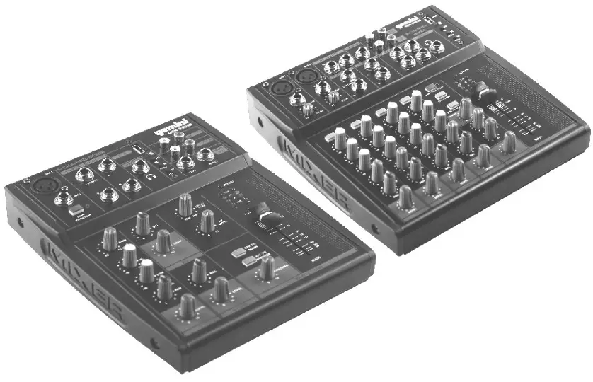
GEM-5USB & GEM-8USBPortable Mixing Console
GEM—5USB & GEM-8USBPORTABLE MIXING CONSOLE
Introduction
Congratulations! With the GEM series you have purchased a state-of-the-art mixing console that sets new standards. Our prime goal when develping the mixer was to design a console that can be used for a great variety of applications. And to give you maximum flexibility. In combination with its comprehensive range of features and pro-level connections, the mixer will be your perfect tool for any kind of application: broadcasting, video dubbing or mixing a live band.
Before You Begin
Your mixer was carefully packed and the packaging is designed to protect the unit from rough handling. Nevertheless, we recommend that you carefully examine the packaging and its contents for any signs of physical damage, which may have occurred during transit.Be sure that there is enough space around the unit for cooling and please do not place the mixer on any hot surface.
GEM-08USB 8 Channel Mixer Control Elements
- MIC Use this balanced XLR jack to connect a microphone to the mixer.– The phantom power required for condenser mics can be activated with switch PHANTOM
- Channel 1 features an additional LINE 1 input on a balanced 1/4” jack.
- Use the GAIN control to adjust the input gain. This control should always be turned fully counterclockwise whenever you connect or disconnect a signal source to one of the inputs.
- In addition, the mono channels are equipped with a steep LOW CUT filter (slope at 18 dB/Oct, -3 dB at 75 Hz) designed to eliminate unwanted low-frequency signal components.
- The upper (HIGH) and the lower band (LOW) are shelving filters that increase or decrease all frequencies above or below their cut-off frequency.The cut-off frequencies of the upper and lower band are 12 kHz and 80 Hz respectively. The MID band is configured as a peak filter with a center frequency of 2.5 kHz.
- EFF sends enable you to feed signals via a variable control from one or more channels and sum these signals to a bus. The bus appears at the console’s EFF sent to output and can be fed from there to an external effects device. The return from the effects unit is then brought back into the console on the stereo channels. Each EFF send is mono and features up to +10 dB gain.
- The PAN control determines the position of the channel signal within the stereo image. This control features a constant-power characteristic, which means the signal is always maintained at a constant level, irrespective of position in the stereo panorama.
- The PK LEDs of the mono channels illuminate when the input signal is driven too high, which could cause distortion. If this happens, use the GAIN control to reduce the preamp level until the LED does not light anymore.
- The LEVEL control determines the level of the channel signal in the main mix.
- LINE IN Each stereo channel has two balanced line-level inputs on 1/4” jacks for left (L/MONO) and right (R) channels. If you use only the (L/MONO) jack, the same sound is output from both Left and right speakers.
- 7/8 AUX RET the STEREO AUX RETURN connectors are used to bring the output of the external effects device (whose input is derived from the aux sends) back into the console. You can instead use these connectors as additional inputs, but any effects device will then have to be brought back into the console via a normal stereo channel. This does, however, give you the ability to use the channel EQ on the effects return signal if you wish.
- The EFF SEND control adjusts the volume level of the EFF signal provided at connector EFF SEND.
- REC OUT These connectors are wired in parallel with the MAIN OUT and carry the main mix signal (unbalanced). Connect the 2-TRACK OUTPUT to the inputs of your recording device. The output level is adjusted via the high-precision MAIN MIX fader or rotary control.
- 2TK RET The 2-TRACK INPUTS are used to bring an external signal source (e.g. CD player, tape deck, Etc.) into the console.
- USB/BluetoothPlay/Pause switch. Long press this key until the indicator flashes.Then turn on the phone Bluetooth, search until the phone shows the Bluetooth link of the mixer, join the link until the connection is successful.Vol+/Next Press once to skip to the next song. Press and hold for volume up.Vol-/Prev Press once to song skip to prev song. Press and hold for volume down.
- The MAIN OUT connectors are unbalanced mono jacks. The main mix signal appears here at a Level of 0 dBu. The MAIN MIX fader adjusts the volume of these outputs.
- The unbalanced OUT jacks carry the summed effects and main mix signals, as well CTRL ROOM as soloed channel signals.
- Use the PHONES jack to connect a pair of headphones.
- The red + 48V LED lights up when phantom power is on. The PHANTOM switch activates the phantom power supply on the XLR connectors of all mono channels.
- When the 2 TK TO MIX switch is depressed, the 2-track input is assigned to the main mix providing additional input for tape machines, MIDI instruments or other signal sources that do not require any processing.
- Level indicator The high-precision 4-segment display accurately displays the relevant signal level.
- Press the 2 TK TO CTRL RM switch if you want to monitor the 2-track input via the CTRL ROOM OUT. This provides an easy way to monitor signals coming back from tape to ensure that they are recording correctly.
- The PHONES/CTRL RM control adjusts the level of both headphones and CTRL RM outputs.
- The is used for adjusting the time interval of echo repeat. The middle position (5) makes DELAY TIME most effective.
- The EFF control adjusts the volume of the effect for the corresponding channel.
- Use the MAIN fader to set the overall volume level of your mixer.
- The 7/s AUX RET control determines the level of the 7/8 AUX RET JACK channel signal in the main mix.
GEM-08USB 8 Channel Mixer
GEM 05USB 5 Channel Mixer
5 .5 Channel Mixer Control Elements
- Use this balanced XLR jack to connect a microphone to the mixer
- Channel 1 features an additional LINE1 input 0″ a b<‘=\|a”¢ed I/4” Ia¢I<
- Use thIS SWItCI‘I t0 activate the phantom power required fOI’ condenser microphones
- Channels 2/3 feature an additional LINE2/3 input on a balanced 1/4” jack
- Channels 4/5 feature an additional LINE4/5 input on a balanced 1/4” jack.
- Use the PHONES jack to connect a commercially available pair of headphones.
- USB/BluetoothPlay/Pause switch. Long press this key until the indicator flashes. Then turn on the phone Bluetooth, search until the phone shows the Bluetooth link of the mixer, join the link until the connection is successful.Vol+/Next Press once to skip to the next song. Press and hold for volume up.Vol-/Prev Press once to song skip to prev song. Press and hold for volume down.
- The control determines the channel’s input gain both for a microphone connected via the GAIN MIC XLR jack and for other signal sources connected to the 1/4” jack.
- HIGH has a function that controls the high-frequency tone of each channel. Always set this control to the 12 o’clock position, but you can control the high-frequency tone according to the speaker the conditions of the listening position, and the listener’s taste. Clockwise rotation of the control increases level, and vice versa.
- LOW has a function that controls the low-frequency tone of each channel.Always set this to control the 12 o’clock position, but you can control the low-frequency tone according to the speaker, the conditions of listening position, and the listener’s taste. Clockwise rotation of the control increases the level and vice versa.
- Use the PAN control to adjust the position of the signal on a stereo basis.
- The LEVEL fader adjusts the volume of the corresponding channel.
- Use the PAN control to adjust the position of the signal on a stereo basis.
- Use the REC OUT jacks to connect, for example, a tape deck for recording applications.
- The TAPE IN jack stereo RCA allows for the connection of play-back devices such as CD players, etc.
- These are the balanced 1/4” jack MAIN OUT of your mixer that can be used to drive, e.g. a power amplifier.Main Section
- DELAY TIME is used for adjusting the time interval of echo repeat.The middle position (5) is most effective.
- The LEDs read the output level of your mixer. Make sure that the two clip LEDs won’t light up.
- The FX level control adjusts the volume of the effect of the corresponding channel.
- When the 2TK TO the MAIN switch is depressed, the 2-track input is assigned to the main mix proceeding an additional input for tape machines, MIDI instruments or other signal source that do not require any processing.
- Press the 2TK TO PHONES to switch if you want to monitor the 2 track input via the PHONE out.This provides an easy way to monitor signals coming back from tape to ensure that they are recording correctly.
- Use the MAIN fader to set the overall volume level of your mixer.
- The PHONES control adjusts the headphone’s volume.
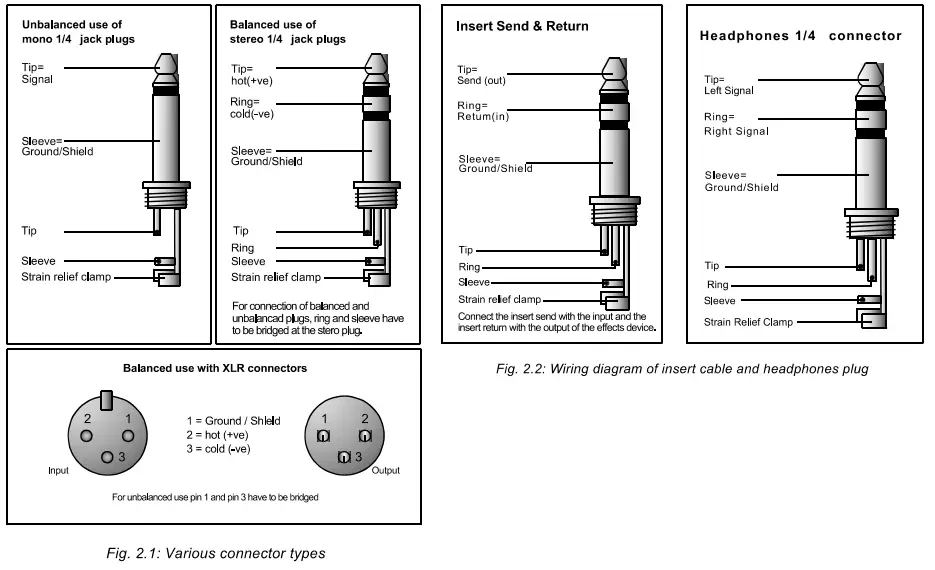
Wiring
SPECIFICATIONS FEATURE:
- 5/8 standard inputs
- 1/2 balanced MIC/LINE inputs
- 3 band frequency equalizer
- 1 phantom power
- 2/4 stereo input
- 2TK input & REC output
- tow level LED indicate display
report this adTECHNICAL DATA:
| Common mode reje | -80dBu |
| S/N Ratio: | -82dB |
| Frequency response: | +/-0.5dB 2OHz-2OKHz |
| T H D: | lassthan <0.03%@1 KHz |
| INPUT LEVEL: | |
| MIC input: | +60dBu |
| LlNEinput: | +30dB |
| stereo input: | +20dBu |
| headphones output(2OO Ω) | mW |
| arametric EQ: | |
| HIGH: | 12khZ, +/-15dB |
| LOW: | 8OHZ, +/-15dB |
WARRANTY AND REPAIR:All Gemini products are designed and manufactured to the highest standards in the industry. With proper care and maintenance, your product will provide years of reliable service.
LIMITED WARRANTY
A. Gemini guarantees its products to be free from defects in materials and workmanship for one (1) year from the original purchase date. Exceptions: Laser assemblies on CDPlayers, cartridges, and crossfaders are covered for 90 days.B. This limited warranty does not cover damage or failure caused by abuse, misuse, abnormal use, faulty installation, improper maintenance or any repairs other than thoseprovided by an authorized Gemini Service Center.C. There are no obligations of liability on the part of Gemini for consequential damages arising out of or in connection with the use or performance of the product or other indirect damages with respect to loss of property, revenues, of profit, or costs of removal, installation, or reinstallation. All implied warranties for Gemini, including impliedwarranties for fitness, are limited in duration to one (1) year from the original date of purchase unless otherwise mandated by local statutes.
RETURN/REPAIR
A. In the U.S.A., please call our helpful Customer Service Representatives at (732) 346-0061, and they will be happy to give you a Return Authorization Number (RA#) and the address of an authorized service center closest to you.B. After receiving an RA#, include a copy of the original sales receipt, with the defective product and a description of the defect. Send by insured freight to: Gemini and use the address provided by your customer service representative. Your RA# must be written on the outside of the package, or processing will be delayed indefinitely!C. Service covered under warranty will be paid for by Gemini and returned to you. For non-warrantied products, Gemini will repair your unit after payment is received. Repaircharges do not include return freight. Freight charges will be added to the repair charges.D. On warranty service, you pay for shipping to Gemini, we pay for return shipping within the continental United States. Alaska, Hawaii, Puerto Rico, Canada, Bahamas, and the Virgin Islands will be charged for freight.E. Please allow 2-3 weeks for the return of your product.Under normal circumstances, your product will spend no more than IO working days at Gemini. We are not responsible for shipping times.
IN THE USA:If you experience problems with this unit, call 732-346-0061 for Gemini customer service.Do not attempt to return this equipment to your dealer.Parts of the design of this product may be protected by worldwide patents. Information in this manual is subject to change without notice and does not represent a commitment on the part of the vendor. Gemini shall not be liable for any loss or damage whatsoever arising from the use of information or any error contained in this manual. No part of this manual may be reproduced, stored in a retrieval system, or transmitted, in any form or by any means, electronic, electrical, mechanical, optical, chemical, including photocopying and recording, for any purpose without the express written permission of Gemini. It is recommended that all maintenance and service on this product is performed by Gemini or its authorized agents. Gemini will not accept liability for loss or damage caused by maintenance or repair performed by unauthorized personnel.Gemini Worldwide Headquarters458 Florida Grove Rd. – Perth Amboy, NJ 08861 – USA – Tel: (732)346-0061 – Fax: (732)346-0065
Follow us on Social Media!@GeminiSoundHQFor any questions, concerns or to makereturns, please contact us directlyat 1-844-GEMlNl9www.geminisound.com
Register your product online atwww.GEMINISOUND.COMto be eligible for great prize giveaways!
© Innovative Concepts and Design LLC, All Rights Reserved.
References
[xyz-ips snippet=”download-snippet”]