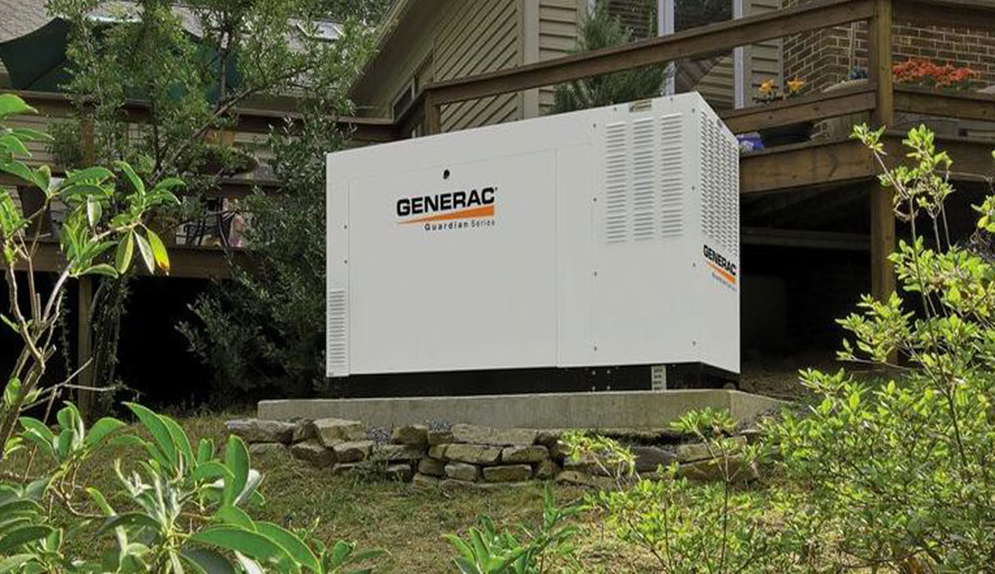
GENERAC RG048 Standby Generators Liquid-Cooled Gaseous Engine
INCLUDES
- Two-Line LCD Multilingual Digital Evolution™ Controller (English/Spanish/French/Portuguese) With External Viewing Window for Easy Indication of Generator Status and Breaker Position.
- Electronic Engine Control Module Optimized for Power Generating.
- Isochronous Electronic Governor
- Sound Attenuated Enclosure
- Closed Coolant Recovery System
- Smart Battery Charger
- UV/Ozone Resistant Hoses
- ±1% Voltage Regulation
- Field Convertible Fuel Type With No Mechanical Adjustment Required.
- 5 Year Limited Warranty
- UL 2200 Listed
Standby Power RatingModel RG048 (Aluminum – Bisque) – 48 kW 60 Hz
FEATURES
- INNOVATIVE DESIGN & PROTOTYPE TESTING are key components of GENERAC’S success in “IMPROVING POWER BY DESIGN.” But it doesn’t stop there. Total commitment to component testing, reliability testing, environmental testing, destruction and life testing, plus testing to applicable CSA, NEMA, EGSA, and other standards, allows you to choose GENERAC POWER SYSTEMS with the confidence that these systems will provide superior performance.
- TEST CRITERIA
- PROTOTYPE TESTED
- SYSTEM TORSIONAL TESTED
- NEMA MG1-22 EVALUATION
- MOTOR STARTING ABILITY
- SOLID-STATE, FREQUENCY COMPENSATED VOLTAGE REGULATION. This state-of-the-art power maximizing regulation system is standard on all Generac models. It provides optimized FAST RESPONSE to changing load conditions and MAXIMUM MOTOR STARTING CAPABILITY by electronically torque-matching the surge loads to the engine. Digital voltage regulation at ±1%.
- SINGLE SOURCE SERVICE RESPONSE from Generac’s extensive dealer network provides parts and service know-how for the entire unit, from the engine to the smallest electronic component.
- GENERAC TRANSFER SWITCHES. Long life and reliability are synonymous with GENERAC POWER SYSTEMS. One reason for this confidence is the GENERAC product line is offered with its own transfer systems and controls for total system compatibility.
48 kW
GENERATOR SPECIFICATIONS
| Type | Synchronous |
| Rotor Insulation Class | F (48 kW) |
| Stator Insulation Class | H |
| Telephone Interference Factor (TIF) | <50 |
| Alternator Output Leads 1-Phase | 4 wire |
| Alternator Output Leads 3-Phase | 6 wire |
| Bearings | Sealed Ball |
| Coupling | Flexible Disc |
| Excitation System | Direct |
VOLTAGE REGULATION
| Type | Electronic |
| Sensing | Single Phase |
| Regulation | ± 1% |
GOVERNOR SPECIFICATIONS
| Type | Electronic |
| Frequency Regulation | Isochronous |
| Steady State Regulation | ± 0.25% |
ELECTRICAL SYSTEM
| Battery Charge Alternator | 12 Volt 30 Amp |
| Static Battery Charger | 2.5 Amp |
| Recommended Battery (battery not included) | Group 27F (48kW), 725CCA |
| System Voltage | 12 Volts |
GENERATOR FEATURES
- Revolving field heavy duty generator
- Directly connected to the engine
- Operating temperature rise 120°C above a 40°C ambient Class H insulation is NEMA rated
- Class F insulation is NEMA rated
- All models fully prototyped tested
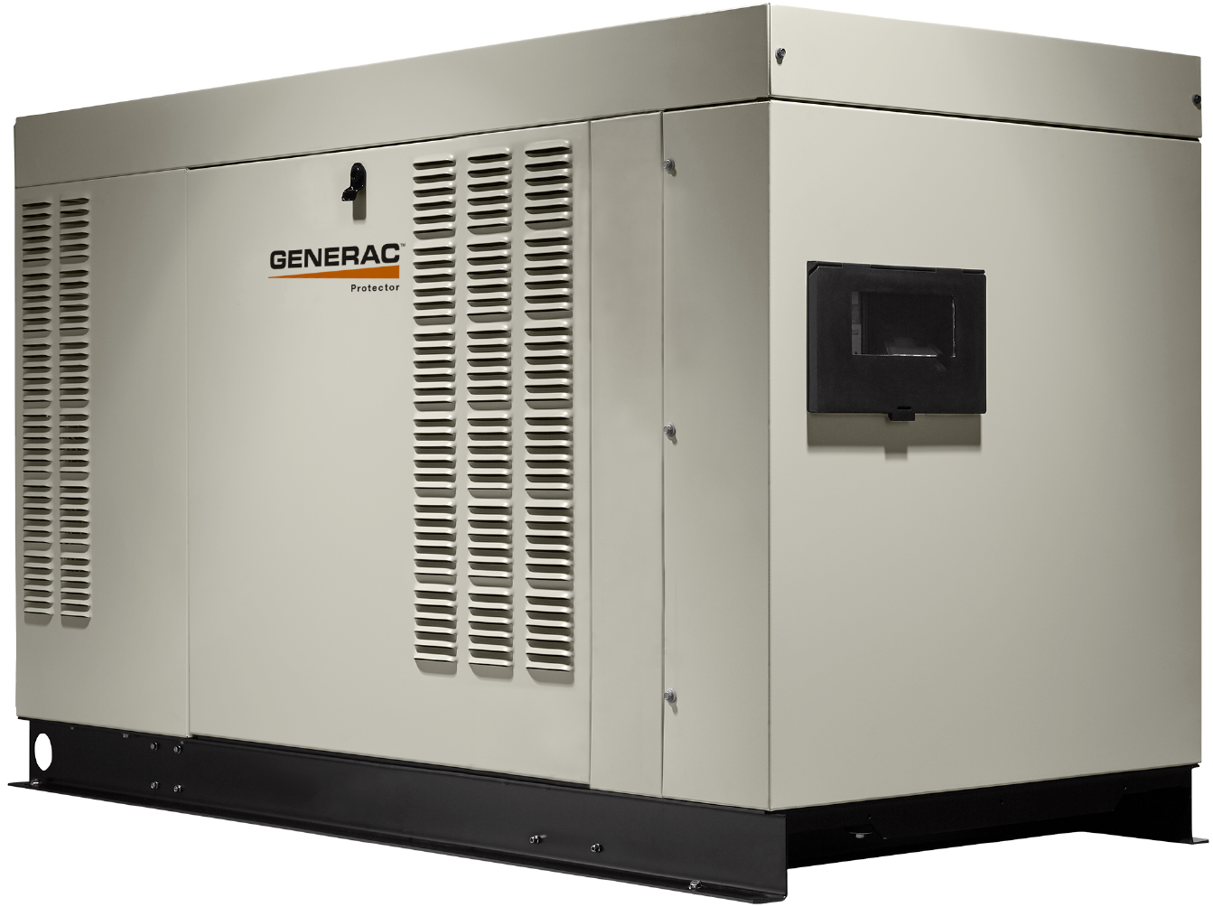
ENCLOSURE FEATURES
| Aluminum weather protective enclosure | Ensures protection against mother nature. Electrostatically applied textured epoxy paint for added durability. |
| Enclosed critical grade muffler | Quiet, critical grade muffler is mounted inside the unit to prevent injuries. |
| Small, compact, attractive | Makes for an easy, eye appealing installation. |
| SAE | Sound attenuated enclosure ensures quiet operation. |
ENGINE SPECIFICATIONS: 48 kW
| Make | Generac |
| Model | Inline 4 cylinder |
| Cylinders | 4 |
| Displacement (Liters) | 4.5 |
| Bore (in/mm) | 4.5/114.3 |
| Stroke (in/mm) | 4.25/107.95 |
| Compression Ratio | 9.9:1 |
| Intake Air System | Naturally Aspirated |
| Lifter Type | Hydraulic |
ENGINE LUBRICATION SYSTEM
| Oil Pump Type | Gear |
| Oil Filter Type | Full Flow Spin-On Cartridge |
| Crankcase Capacity (qt/l) | 11.6/11 (48 kW) |
ENGINE COOLING SYSTEM
| Type | Ethylene Glycol 50/50 Mix |
| Water Pump | Belt-Driven |
| Fan Speed (rpm) | 2,100 |
| Fan Diameter (in/mm) | 20 |
| Fan Mode | Pusher |
FUEL SYSTEM
| Fuel Type | Natural Gas, Propane Vapor |
| Fuel Shut Off Solenoid | Standard |
| Operating Fuel Pressure | 3.5-14 Water Column/9-26 mmHG |
| LP Fuel Pressure | 7 – 14″ Water Column |
| NG Fuel Pressure | 3.5 – 14″ Water Column |
GENERATOR OUTPUT VOLTAGE/kW – 60 Hz
|
kW LPG |
Amp LPG |
kW Nat. Gas |
Amp Nat. Gas |
CB Size (Both) |
||
| RG048 | 120/240 V, 1Ø, 1.0 pf |
48 |
200 |
48 |
200 |
200 |
| 120/208 V, 3Ø, 0.8 pf |
48 |
167 |
48 |
167 |
175 |
|
| 120/240 V, 3Ø, 0.8 pf |
48 |
144 |
48 |
144 |
150 |
|
| 277/480 V, 3Ø, 0.8 pf |
48 |
72 |
48 |
72 |
80 |
SURGE CAPACITY IN AMPS
| Voltage Dip @ < .4 pf | |||
|
15% |
30% |
||
|
RG048 |
120/240 V, 1Ø |
100 |
300 |
|
120/208 V, 3Ø |
118 |
242 |
|
|
120/240 V, 3Ø |
97 |
189 |
|
|
277/480 V, 3Ø |
63.6 |
122.8 |
ENGINE FUEL CONSUMPTION
|
RG048 |
Exercise cycle |
— |
— |
— |
— |
— |
| 25% of rated load |
201 |
5.7 |
2.88 |
104.7 |
10.9 |
|
| 50% of rated load |
336 |
9.5 |
4.16 |
151.3 |
15.7 |
|
| 75% of rated load |
447 |
12.7 |
5.28 |
192 |
20 |
|
| 100% of rated load |
604 |
17.1 |
6.61 |
240.4 |
25 |
Note: Fuel pipe must be sized for full load.For Btu content, multiply ft³/hr x 2520 (LP) or ft³/hr x 1000 (NG)For megajoule content, multiply m³/hr x 93.15 (LP) or m³/hr x 37.26 (NG)Refer to “Emissions Data Sheets” for maximum fuel flow for EPA and SCAQMDpermitting purposes.
STANDBY RATING: Standby ratings apply to installations served by a reliable utility source. The standby rating is applicable to varying loads for the duration of a power outage. There is no overload capability for this rating. Ratings are in accordance with ISO-3046-1. Design and specifications are subject to change without notice.
ENGINE COOLING
| Air Flow (inlet air including alternator and combustion air in cfm/cmm) |
2,829/80.1 |
| System Coolant Capacity (gal/liters) |
2.9/11 |
| Heat Rejection to Coolant (BTU per hr/MJ per hr) |
201,060 |
| Maximum Operation Air Temperature on Radiator (°C/°F) |
60/150 |
| Maximum Ambient Temperature (°C/°F) |
50/140 |
COMBUSTION REQUIREMENTS
| Flow at Rated Power (scfm/cmm) |
92.7/2.6 |
SOUND EMISSIONS
| Sound Output in dB(A) at 23 ft (7 m) With Generator in Exercise Mode* |
68 |
| Sound Output in dB(A) at 23 ft (7 m) With Generator Operating at Normal Load* |
70 |
EXHAUST
| Exhaust Flow at Rated Output (scfm/cmm) |
104/10.6 |
| Exhaust Temperature at Muffler Outlet (°C/°F) |
507/945 |
ENGINE PARAMETERS
| Rated Synchronous rpm |
1,800 |
POWER ADJUSTMENT FOR AMBIENT CONDITIONS
Temperature Deration ………………………………… 3% for every 10°C above 25°C or 1.65% for every 10°F above 77°F
Altitude Deration ……………………………………….. 1% for every 100 m above 183 m or 3% for every 1000 ft above 600 ft
CONTROLLER FEATURES
- Two-Line Plain Text LCD Display: Simple user interface for ease of operation.
- Mode Switch:Auto: Automatic Start on Utility failure. 7 day exerciserOff: Stops unit. Power is removed. Control and charger still operate.Manual: Start with starter control, unit stays on. If utility fails, transfer to load takes place.
- Programmable Start Delay Between 10-30 Seconds: 10 sec standard
- Engine Start Sequence: Cyclic cranking: 16 sec on, 7 rest (90 sec maximum duration)
- Engine Warm-up: 5 sec
- Engine Cool-Down: 1 min
- Starter Lock-Out: Starter cannot re-engage until 5 sec after engine has stopped.
- Smart Battery Charger: Standard
- Automatic Voltage Regulation With Over and Under Voltage Protection: Standard
- Automatic Low Oil Pressure Shutdown: Standard
- Overspeed Shutdown: Standard, 72 Hz
- High Temperature Shutdown: Standard
- Overcrank Protection: Standard
- Safety Fused: Standard
- Failure to Transfer Protection: Standard
- Low Battery Protection: Standard
- 50 Event Run Log: Standard
- Future Set Capable Exerciser: Standard
- Incorrect Wiring Protection: Standard
- Internal Fault Protection: Standard
- Common External Fault Capability: Standard
- Governor Failure Protection: Standard
|
Model # |
Product |
Description |
| G0071690 | Mobile Link® 4G LTE Cellular Accessory | Generac’s Mobile Link allows you to check the status of your generator from anywhere that you have access to an Internet connection from a PC or with any smart device. You will even be notified when a change in the generator’s status occurs via e-mail or text message. Note: Harness Adapter Kit required.Available in the U.S. only. |
| G006478-0 | Kit, Adapter Mobile Link L/C (Required for QT and RG Series) | The Harness Adapter Kit is required to make liquid-cooled units compatible with Mobile Link™ |
| G007992-0 | Cold Weather Kit | If the temperature regularly falls below 32 °F (0 °C), install a cold weather kit to maintain optimal battery temperature. Kit consists of battery warmer with thermostat built into the wrap. |
| G007990-0 | Extreme Cold Weather Kit | Recommended where the temperature regularly falls below 32 °F (0 °C) for extended periods of time. For liquid cooled units only. |
| G005651-0 | Base Plug Kit | Add base plugs to the base of the generator to keep out debris. |
| G005703-0 – Bisque | Paint Kit | If the generator enclosure is scratched or damaged, it is important to touch-up the paint to protect from future corrosion. The paint kit includes the necessary paint to properly maintain or touch-up a generator enclosure. |
| G007991-0 | Scheduled Maintenance Kit | The Liquid-Cooled Scheduled Maintenance Kits offer all the hardware necessary to perform complete maintenance on Generac liquid-cooled generators. |
| G006664-0 | Local Wireless Monitor | Completely wireless and battery powered, Generac’s wireless remote monitor provides you with instant status information without ever leaving the house. |
| G006665-0 | Wireless Remote Extension Harness | Recommended for use with the Wireless Remote on units up to 60 kW, required for use on units 70 kW or greater. |
| G007993-0 | E-Stop | E-stop allows for immediate fuel shutoff and generator shutdown in the event of an emergency. |
| G007005-0 | Wi-Fi LP Fuel Level Monitor | The Wi-Fi enabled LP fuel level monitor provides constant monitoring of the connected LP fuel tank. Monitoring the LP tank’s fuel level is an important step in making sure your generator is ready to run during an unexpected power failure. Status alerts are available through a free application to notify when your LP tank is in need of a refill. |
| G007000-0 (50 amp) G007006-0(100 amp) | Smart Management Module | Smart Management Modules (SMM) are used to optimize the performance of a standby generator. They manage large electrical loads upon startup and shed them to aid in recovery when overloaded. In many cases, using SMM’s can reduce the overall size and cost of the system. |
| A0000018981 | Ultrasonic Cleaner Solution | An ultra-concentrated anti-corrosive cleaning solution engineered to reach the smallest cavities to clean the toughest contaminants. This water based formula is non-toxic, biodegradable, safe for both metal and plastic surfaces and is superior in risibility. |
| A0000019001 | Corrosion Inhibitor & Protectant | A plastic, rubber, leather, and vinyl surface protectant designed for use following a thorough cleaning with the A0000018981 Ultrasonic Cleaner Solution. It helps protected surfaces stay clean longer as a dry lubrication, polish, and wax. Aids in snow and grass release and odor control. |
|
WEIGHT DATA |
||||
|
ENGINE/KW |
ENCLOSURE MATERIAL |
WEIGHT GENSET ONLY KG [LBS] |
WEIGHT SHIPPING SKID KG [LBS] |
SHIPPING WEIGHT KG [LBS] |
|
4.5L/48KW |
AL |
808 [1781] |
51 [112] |
859 [1893] |
| SERVICE ITEM |
4.5L |
| OIL FILL CAP |
LEFT SIDE |
| OIL DIP STICK |
LEFT SIDE |
| OIL FILTER |
LEFT SIDE |
| OIL DRAIN HOSE |
RIGHT SIDE |
| RADIATOR DRAIN HOSE |
RIGHT SIDE |
| COOLANT RECOVERY BOTTLE |
RIGHT SIDE |
| RADIATOR FILL CAP |
ROOF TOP |
| AIR CLEANER ELEMENT |
LEFT SIDE |
| SPARK PLUGS |
LEFT SIDE |
| MUFFLER |
SEE NOTE 11 |
| DRIVE BELT |
EITHER SIDE |
| BATTERY |
LEFT SIDE |
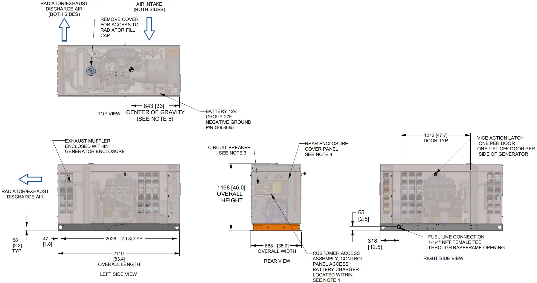
NOTES:
- MINIMUM RECOMMENDED CONCRETE PAD SIZE IS 6″ OFFSET OF OVERALL LENGTH AND WIDTH OF GENERATOR. {1193.8 (47″) WIDE X 2423.2 (95.4″) LONG}. REFERENCE INSTALLATION GUIDE SUPPLIED WITH THE UNIT FOR CONCRETE PAD GUIDELINES.REFERENCE MANUFACTURER’S SPECIFICATIONS IF USING ENGINEERED, PREFABRICATED SLABS.
- ALLOW SUFFICIENT ROOM ON ALL SIDES OF THE GENERATOR FOR MAINTENANCE AND SERVICING. THIS UNIT MUST BE INSTALLED IN ACCORDANCE WITH CURRENT APPLICABLE NFPA 37 AND NFPA 70 STANDARDS AS WELL AS ANY OTHER FEDERAL, STATE, AND LOCAL CODES.
- CONTROL PANEL / CIRCUIT BREAKER INFORMATION:
- SEE SPECIFICATION SHEET OR OWNERS MANUAL
- ACCESSIBLE THROUGH CUSTOMER ACCESS ASSEMBLY DOOR ON REAR OF GENERATOR.
- REMOVE THE REAR ENCLOSURE COVER PANEL TO ACCESS THE STUB-UP AREAS AS FOLLOWS:
- HIGH VOLTAGE CONNECTION INCLUDING AC LOAD LEAD CONDUIT CONNECTION NEUTRAL CONNECTION, BATTERY CHARGER 120 VOLT AC (0.5 AMP MAX) CONNECTION.
- LOW VOLTAGE CONNECTION INCLUDING TRANSFER SWITCH CONTROL WIRES.
- CENTER OF GRAVITY AND WEIGHT MAY CHANGE DUE TO UNIT OPTIONS.
- BOTTOM OF GENERATOR SET MUST BE ENCLOSED TO PREVENT PEST INTRUSION AND RECIRCULATION OF DISCHARGE AIR AND/OR IMPROPER COOLING AIR FLOW.
- REFERENCE OWNERS MANUAL FOR LIFTING WARNINGS.
- MOUNTING BOLTS OR STUDS TO MOUNTING SURFACE SHALL BE 5/8-11 GRADE 5 (USE STANDARD SAE TORQUE SPECS)
- MUST ALLOW FREE FLOW OF INTAKE AIR, DISCHARGE AIR AND EXHAUST. SEE SPEC SHEET FOR MINIMUM AIR FLOW AND MAXIMUM RESTRICTION REQUIREMENTS.
- GENERATOR MUST BE INSTALLED SUCH THAT FRESH COOLING AIR IS AVAILABLE AND THAT DISCHARGE AIR FROM RADIATOR IS NOT RECIRCULATED.
- EXHAUST MUFFLER ENCLOSED WITHIN GENERATOR ENCLOSURE, REMOVE FRONT PANEL TO ACCESS.
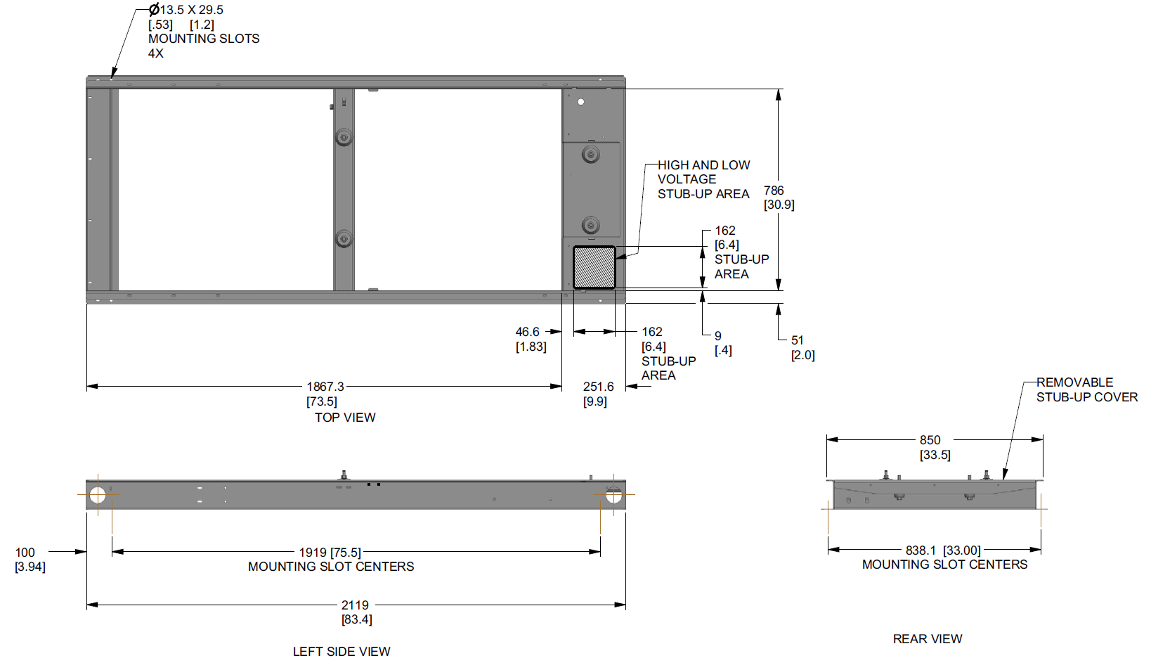
*NOTE:STUB-UP AREA FOR HIGH AND LOW VOLTAGE CONNECTIONS, CIRCUIT BREAKER, NEUTRAL AND CUSTOMER CONNECTION OPENING.
 report this ad
![]()
References
[xyz-ips snippet=”download-snippet”]