![]()
GEOPHINEX Under Ground Worlds Best Water Detector- Scientific Water Detector-Advanced Vlf Vhf Frequency User Manual
![]()
DEVICE COMPONENT LIST
- Long Range Locator System:

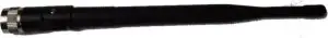
- Transmitting Antenna
- Receiving Antenna
- Handle
- Power Bank
- Charger
WORKING PROCEDURE
- Connect Handle To Device
- Connect The Receiving and Transmitting Antennas
HOW TO OPERATE THE DEVICE
- The Device is switched ON by using the ON-OFF switch on the side of the device
- The unit initializes and goes to the next screen
- The Device Works on 3 Languages (English, German, and French). Select your option by touching the screen.
- The scanning range will then appear on display. You can enter appropriate value on the screen. For example (default selection value is 200 feet). This can be incremented or decremented by the ‘+’ symbol and ‘-‘symbol on both sides of the scan setting range window. Minimum Default setting is 200, this cannot be decremented. Now press the search screen for bore-well location finding.
- The search screen will appear, which will start the device. There will be intermittent beep sound to indicate the search in progress.
- The device should be pointed or positioned towards south direction during the initial phase of the start process.
- The search is started by holding the device on the handa) The device will turn towards right-side, if the target is on the right sideb) If the target is on the left side, the device will turn towards left-sidec) Device will turn back(180 degree)/rotates, when you pass/near the targetd) Then you can stop & point the target 5 Meter Squaree) After detecting the target confirm the target from eachdirection
- Mark the center point of the target, this is defined as the Target point/ Bore-Well point
- From the Bore point, make cross lines in the direction of North (N) to South (S) and another line running from East (E) to West (W). The two drawn lines meet at target point/ Bore point.
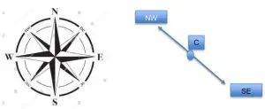
- For calculating aquifer depth or fracture depth, now draw lines @ 45 degree in the direction of North East (NE) and North West (NW). Similarly, draw another 2 lines at 45 degree towards South West (SW) and South East (SE) as shown below:
- Standing at the center point (C), press the depth calculation display on the screen, the search for depth calculation begins. Now, pointing the machine towards NW, move in that direction along the line drawn as said in point no.10. The Machine will turn back 180 degree after few feet’s of movement. Return to center point.
- Similarly, now, pointing the machine towards NE, move in that direction along the line drawn as said in point no.10. The Machine will turn back 180 degree after few feet’s of movement.
- Repeat the above said procedure described in point 12 for SW and SE direction lines. Once the above said procedures are completed, click the on screen “Finish Button” to calculate for automatic depth and Bore-hole diameter display.
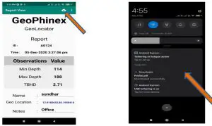
- The screen shot of the reporting display is shown below for your reference.
WARNINGS:
- Make sure that all precautions are taken against risks.
- Do not use your device while it is raining or on extreme weather
- Turn on your device after you make sure that all parts are in place.
- Make sure that battery of your device is fully charged before scanning.
- If the indicator light on the unit is not glowing constant, it is time for recharge. Recharge the unit using power Bank or through Adopter
- We recommend reading the user manual before start working on the device to understand everything and to avoid mistakes in doing the search.
- Main unit of the device is under warranty against all electronic breakdown for two (2) years.
- Damages caused by user errors (External damages, hits, harms etc.) are not covered under this warranty.
- You should follow the instructions in this user manual strictly to minimize the possible faults and to use your device correctly.
How to pair the device with mobile
- Switch ON the Device and then switch ON wi-fi, Gps and mobile data on your phone.
- Search for wi-fi “Geophinex or Geophinex3D” in your mobile and connect the target device by using the password “12345678”.
- Open the geophinex application in your mobile.
Geophinex application in your mobile
- Through your mobile application, the Device can be controlled. The Device’s button operations like home, up, down, enter can be controlled/ Operated. For this you have to go to the option in mobile app as shown below. Click on the 3 dots in the top right corner as indicted in Arrow Mark. It displays short menu. Here you click on “Control” to control the buttons in the device through mobile APP. Similarly, you can generate report by clicking Report icon as shown in picture
2. Click on “Report” to down the Device Report to the Mobile APP for permanent storage. Click the refresh icon on the top of report page to download the data to the mobile APP3. We can also control via the mobile application.
4. Go to report page, enter customer name in the field provided, you can make notes in the notes field like (bore point 1,2 …etc.)5. Press save button to save the data permanently in your mobile. This is displayed as DATA INSERTED in your mobile display.
DETAILED PROFILE REPORT
- Switch OFF the WIFI Network, the “geophinex wi fi” network in your mobile or laptop.
- click backup button to view the surveyed reports.
- Click the required file for which 3D Profile is to be generated
4.As the back up file opens, the system sends data to the cloud for 3D Profile Report Generation
5. Press the download button only if you see report file ready message pop-up in the screen.6. Click the download icon – the profile file in zip format gets download in notification bar
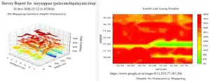
7. A view of the downloaded 3D Profile Report

 report this ad
[xyz-ips snippet=”download-snippet”]