Giant Hydraulic Disc Brake System
IMPORTANT NOTICE
- Contact the place of purchase or Authorized Giant Retailer for information on the detail of installation and maintenance.
- Read this manual completely before attempting to install or work on your Giant Hydraulic Disc Brake System.
- Do not disassemble or alter this product.
- If you encounter difficulties or are uncertain about anything identified in this user’s manual, please contact your local Authorized Giant Retailer
SAFETY WARNINGS & INFORMATION
A) Safety Precautions And Considerations![]() WARNING
WARNING
- This braking system was designed for use on a single rider bicycle. Use of this system on any other vehicle or apparatus will void the warranty, possibly causing you great personal harm and injury.
- Please use extra caution to keep your fingers away from the rotating disc brake rotors. The disc brake rotor is sharp enough to inflict server injury to your fingers if caught within the openings of moving rotor.
- If your bike is involved in a fall or crash, stop and fully check the brake function, including: the lever, caliper, and rotor are securely attached to the bike, pads are correctly installed and functioning, the cable is operating smoothly and the lever feels firm when actuating the brake. Always have a qualified mechanic or your Authorized Giant Retailer check the brakes if you have any doubts.
![]() CAUTION
CAUTION
- Disc Brakes, calipers, rotors and pads get VERY HOT during regular use. DO NOT touch or attempt to service the rotor or caliper, assembly until you’ve allowed for sufficient cooling to occur.
- Pad thickness must be more than 2.5 mm( recommendation values). Confirm this before each ride. Keep pads clean and free of oil or hydraulic fluid. If pads become contaminated discard and replace.
- Cleanliness is a very important part of any maintenance of the Giant Hydraulic Disc Brake System. If the pads or rotor become contaminated with oil, or if the system becomes contaminated with impurities, braking performance will begreatly impaired.
- Ensure that cable housing is always secured to the frame and/or fork prior to every ride. Do not ride a bike on which the cable housing can come into contact with the tires.
B) NOTICE
- If you are unfamiliar with any element of assembly or maintenance of this braking system, please consult a qualified mechanic or your Authorized Giant Retailer for assistance.
- To prevent risks and potential dangers, please keep this product away from children.
ASSEMBLY AND MAINTENANCE
A) NOTE: This product is compatible with Shimano System only and is designed for use ONLY with Giant Contact SL, Contact and Connect stem extensions.
B) TOOLS NEEDED
- 3mm Hex Wrench
- 4mm Hex Wrench
- 5mm Hex Wrench
- T15 Torx® Wrench
- T25 Torx® Wrench
 C) MOUNTING THE ROTOR
![]() WARNING: Important: Operating Giant Hydraulic braking system without out using authorized GIANT rotor disc will void your warranty. Using unauthorized rotor disc may lead to unpredictable braking performance, this may cause serious injuries or possibly death. For Recommended rotor disc please consult an authorized GIANT dealer.
WARNING: Important: Operating Giant Hydraulic braking system without out using authorized GIANT rotor disc will void your warranty. Using unauthorized rotor disc may lead to unpredictable braking performance, this may cause serious injuries or possibly death. For Recommended rotor disc please consult an authorized GIANT dealer.
- Remove wheel from bike.
- Clean the disc and hub-mounting surface with isopropyl alcohol (do NOT use disc brake cleaner).
- Using a TORX T25 wrench, attach the rotor to the hub using supplied bolts and tighten to 4-6 Nm.
- Use a star-pattern sequence to tighten the disc rotor bolts. DO NOT simply tighten them clock-wise or counterclockwise. (Fig. C-1)
NOTE: Be sure the directional indicators on the rotor point in the same direction as therotation of the wheel.![]() CAUTION: DO NOT TOUCH THE DISC IMMEDIATELY AFTER USE – IT WILL BE HOT.
CAUTION: DO NOT TOUCH THE DISC IMMEDIATELY AFTER USE – IT WILL BE HOT.
D) MOUNTING THE CALIPERFor flat mount or post mount adapters, hold the adapter so that the stamped “UP” is oriented upwards. For use without adaptors, proceed directly to next step.Assemble the adapter and front caliper together, tightening torque is 5-7Nm(4mm)(Fig. D-1)NOTE: Tightening torque is 6-8 Nm(5mm) for post mount.Align caliper with frame/fork mounting holes.·
Attach the caliper to the fork or frame using two mounting bolts, but do not fully tighten at this time. (Fig. D-2)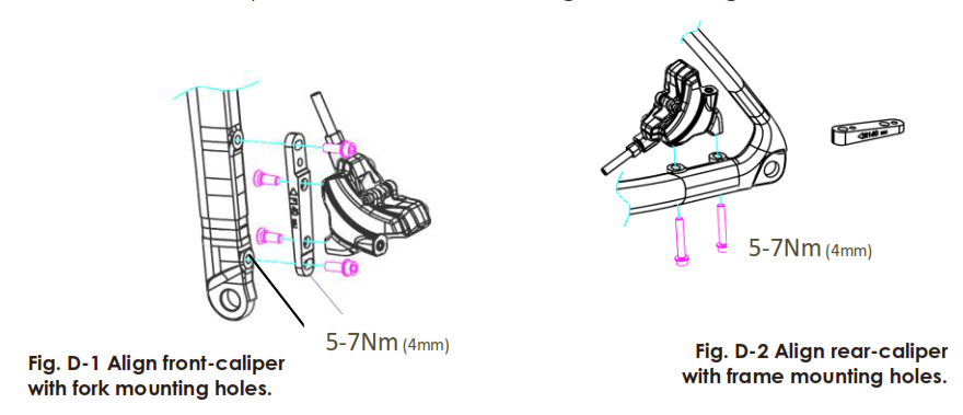
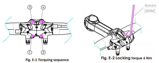
E) MOUNTING THE MASTER CYLINDER BODYNOTE: Giant Hydraulic Disc brake systems are designed for use only with Giant Contact SL, Contact and Connect stems
- Assemble the master cylinder body to stem extension being sure that the hydraulic hoses are facing downwards
- Tighten Stem bolts following the sequence shown (Fig. E-1), fastening torque is 6 Nm (Fig. E-2)

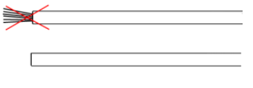
F) Cable Installation· The Braking cable housing are consisted by two types of cable housings (Coiled Cable Housing &Compressionless cable Housing) Coiled cable housing serves as an adopter that protects the braking lever from getting damaged by the compressionless cable housing. Compressionless Housing will provide the best braking performance. For cable installation, cut the compressionless housing to accommodate your bar width and preference. Be sure to cut accurately to minimize tight bends and acute angles for optimized brake lever feel. Confirm that the housing is cut evenly, not frayed and wire strands are not exposed (Fig. F-1). For best braking performance, use compressionless housing with linear wire strands andplease keep the coiled wire housing as short as possible.
Fig. F-1
- The metallic, flexible housing (Fig. F-2) serves as a safety adapter that prevents the control unit housing from being damaged by the compressionless cable housing and also helps reduce cable friction for smooth operation
Fig. F-2
- Assemble the compressionless housing to the flexible housing as shown (Fig. F-3)
 Assemble the compressionless housing to the flexible housing as shown (Fig. F-3)
Fig. F-3![]()
- Insert the male end of F-2 into control unit housing and capped end of F-3 into the Master Cylinder Body, running the housing inside or outside the first bend in the bar as shown below (Fig. F-4).
Fig. F-4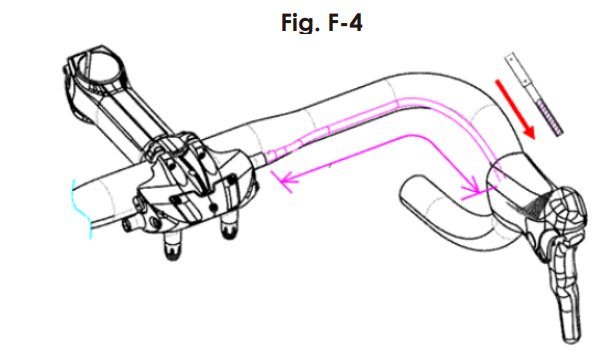
G) Connecting the Brake Cable and Master Cylinder
- Loosen the brake cable screw on the master cylinder body. (Fig. G-1)
NOTE: While operating this procedure please make sure to insert the T15 Torx ® wrench securely into the screw to avoid any stripping issues.
- Run cable through the control unit, housings and through the master cylinder. Pull the cable taut, being careful to NOT add any load to the brake cylinder. (Fig. G-1)
- Tighten the torx T15 cable screw on the related cylinder, maximum torque is 4.5 Nm.
- Ensure the brake cable is secured, cut the unneeded cable and add on the cable tips.
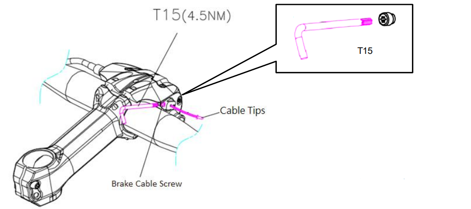
Fig. G-1 Pull cable and tighten
- To align the caliper, securely attach the wheel according to the bicycle owner’s manual, pull the brake lever firmly and hold to self-align the caliper on the rotor while tightening the caliper mounting bolts with a torque of 5-7 Nm (Fig. G-2).
NOTE: Tightening torque is 6-8 Nm(5mm) for post mount.NOTE: NEVER activate the brake system without a rotor or caliper service blocks in place as this will require re-bleeding of the brakes (See Section I)
- Release the lever and check that the pads are aligned equally and that the wheel spins freely without contact between the rotor and brake pads.
- Pull brake lever 10 times to stretch cable and seat housing to ensure there is no air inside the hydraulic system. New cables will stretch slightly after initial installation, repeat the cable tightening process to maintain proper performance.
NOTE: If air is identified in the system, please refer to Section I in this manual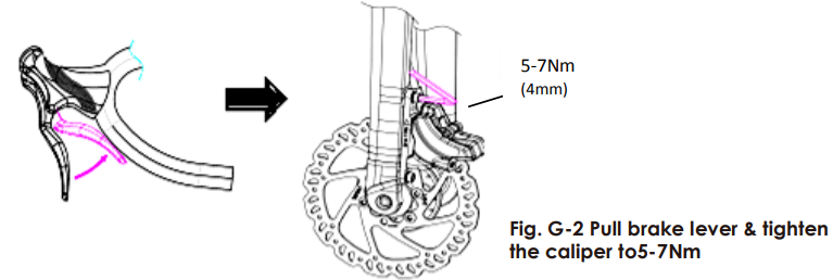
H) Changing Brake Pads![]() WARNING: Important: Operating Giant Hydraulic braking system without out using authorized GIANT braking pad will void your warranty. Using unauthorized braking pad may lead to unpredictable braking performance, this may cause serious injuries or possibly death. For Recommended brake pads please consult an authorized GIANT dealer.
WARNING: Important: Operating Giant Hydraulic braking system without out using authorized GIANT braking pad will void your warranty. Using unauthorized braking pad may lead to unpredictable braking performance, this may cause serious injuries or possibly death. For Recommended brake pads please consult an authorized GIANT dealer.![]() CAUTION: Pad should be replaced when total thickness is less than 2.5mm (friction material & metal plate)or the pad wear indicator appearance. (Fig. H-1)
CAUTION: Pad should be replaced when total thickness is less than 2.5mm (friction material & metal plate)or the pad wear indicator appearance. (Fig. H-1)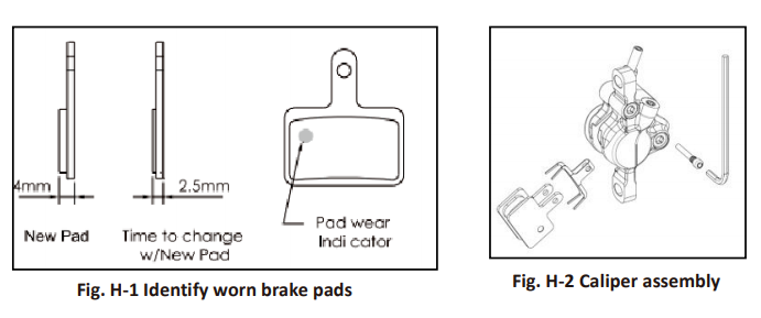
- Remove the wheel from bike.
- Loosen the brake pad assembly bolt with a 3mm hex wrench.
- Pull the cotter pin from the brake pad retaining bolt – be careful not to lose thispiece (Fig. H-2)
- Set the bolt and cotter pin aside. Be careful to save the spring assembly for lateuse.
- Remove the pads from the bottom end of the caliper.
- Install new pads and spring assembly into the calipers in a reverse fashion to theremoval process.
- Reinsert brake pad retainer bolt into the caliper and re-attach the cotter pin.
Tighten the brake pad assembly bolt.
- Repeat for other caliper and adjust cable or pad alignment if necessary.
- Contact your Authorized Giant Retailer for further details as necessary.
![]() WARNING: When the braking pads are worn out please make sure to replace bo pads, this way it insures the same 0.3mm clearance in between the rotor and the braking pad. Uneven clearance may cause major braking failure and result in serious injury.I) Bleed the System
WARNING: When the braking pads are worn out please make sure to replace bo pads, this way it insures the same 0.3mm clearance in between the rotor and the braking pad. Uneven clearance may cause major braking failure and result in serious injury.I) Bleed the System
- Please always use mineral oil for the Giant Hydraulic disc brake.
- You should always bleed the system after you have shortened or replaced the hose or have opened the system to air at any time.
- If the brake action feels spongy, you may improve performance by re-bleeding the system.
- If this is the case, contact your Authorized Giant Retailer or a qualified professional bicycle mechanic to resolve the problem.
- Contact the place of purchase or your Authorized Giant Retailer for further detail information on the bleeding of products that are not found in this user’s manual.
J) NOTICE
- Please do not press the circled cylinder section before the brake assembly is complete. Pressing the cylinder before assembly may cause unexpected braking characteristics. (Fig. J-1)
Please do not remove the screws from the hydraulic cap located the circled cylinder section, by removing the screw may cause unpredictable malfunctions. (Fig. -2)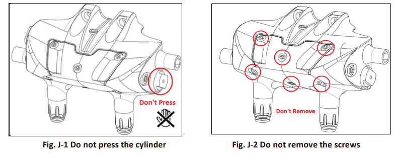
SAFETY CHECK
Before riding the bicycle, check the following items. If you encounter difficulties or are uncertain about problems are found with the following items, please contact your local Giant authorized retailer.
- Spin Wheel to be sure rotors are undamaged and aligned without contact or rub between the rotor and brake pads.
- Check the front and rear brakes work correctly and without any abnormal noises
- Check the disc brake rotor is complete, without crack and deformation.
- Ensure that pads and rotor must be kept clean and free from oil or grease-based contamination.
- Check brake pad thickness – total thickness is more than recommendation values (Fig. H-1).
- Check cable and housing for fraying, excessive friction or damage.
GIANT LIMITED WARRANTY
Giant warrants it’s Giant Hydraulic disc brake system for a period of two (2) years from the date of purchase for the original owner only. This warranty applies only to this product when purchased new from an Authorized Giant Dealer and assembled by that dealer at the time of purchase.LIMITED REMEDYUnless otherwise provided, the sole remedy under the above warranty, or any implied warranty, is limited to the replacement of defective parts with those of equal or greater value at the sole discretion of Giant. This warranty extends from the date of purchase, applies only to the original owner, and is not transferable. In no event shall Giant be responsible for any direct, incidental or consequential damages, including, without limitation, damages for personal injury, property damage, or economic losses, whether based on contract, warranty, negligence, product liability, or any other theory.EXCLUSIONSThe above warranty, or any implied warranty, does not cover:
- Normal wear and tear on parts in situations where there are no assembly or material defects.
- Consumable components including wires, cables, and brake pads.
- Products serviced by other than an Authorized Giant dealer.
- Modifications of the product from its original condition.
- Use of this product for abnormal, competition and/or commercial activities or for purposes other than those for which this product was designed.
- Damage caused by failing to follow the User’s Manual.
- Paint, finish and decal damage resulting from taking part in competitions, jumping, downhill and/or training for such activities or events or as a result of exposing the product to, or operating the product in, severe conditions or climates.
- Labor charges for part replacement or changeover.
Except as is provided by this warranty and subject to all additional warranties, Giant and its employees and agents shall not be liable for any loss or damage whatsoever (including incidental and consequential loss or damage caused by negligence or default) arising from or concerning any Giant product. Giant makes no other warranties, express or implied. All implied warranties,including the warranties of merchantability and fitness for a particular purpose are limited in duration to that of the express warranties stated above. Any claim against this warranty must be made through an Authorized Giant Dealer or distributor. The purchase receipt or other proof of the date of purchase is required before a warranty claim may be processed.
Claims made outside the country of purchase may be subject to fees and additional restrictions.Warranty duration and details may differ by country. This warranty gives you specific legal rights, and you may also have other rights which may vary from place to place. THIS WARRANTY DOES NOT AFFECT YOUR STATUTORY RIGHTS.
[xyz-ips snippet=”download-snippet”]