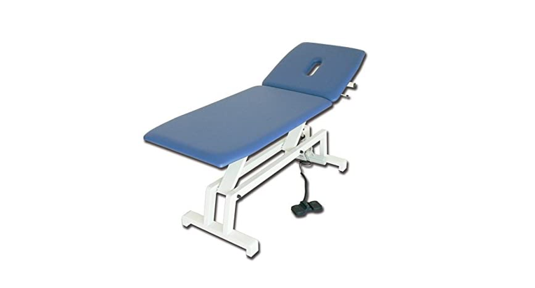
![]() LETTINO ELETTTRICO PER CENTRI BENESSERE ELECTRIC BEAUTY BEDS
LETTINO ELETTTRICO PER CENTRI BENESSERE ELECTRIC BEAUTY BEDS
ABOUT THIS MANUAL
This manual shall only be used for the reference of operation of this particular model. If the manual is used for other purposes, we will not undertake any according to consequences and responsibility. All information of this manual shall be protected by copyright and shall not be copied and translated in any part of this specification without the written consent of the manufacturer.
WARNING
- Power supply must be cut off when changing electrical components or maintaining and cleaning machines.
- The plug must be plugged into an outlet that is properly installed and grounded, to prevent the risk of fire and electric shock.
- Do not stand on this equipment.
- Do not allow children to play with and place the equipment in a place where children can touch. Please adjust the backrest to the highest position when you leave.
- Please do not place the equipment in wet places such as the bathroom to avoid electric shock or another failure; Also keep the controllers away from water.
- Please do not place and operate the equipment in places where is painting/coating or supplying oxygen.
- Unless being monitored or instructed by personnel who can be responsible for their personal safety, the people who have physical obstacles, tactile disorders, mental disorders, lack of experience, common sense or children, are not allowed to use the equipment.
- Please contact the distributor, service center, or related personal with appropriate skill and experience for repairing if the plug is damaged, in case of any danger.
- Please make sure there is no accessible thing within the stroke during any operation of the beds.
- The operation should be processed by trained professionals.
PRECAUTIONS
- The equipment should be used by an experienced person who must be familiar with the product structure, performance, and instructions. And make the regular maintenance work.
- Read this manual carefully before installation, operation, and adjustment. And please keep it well.
- This product shall not be used for single side or single point loading work.
- Comply with safety operation rules, do not overload the use of products, to ensure that the product safety protection equipment is complete andreliable, eliminate unsafe factors on time.
- Tighten bolts and nuts regularly to avoid failure caused by loose, sliding, vibration, and falling parts.
- During the maintenance, the operator shall not disassemble any parts of the bed at will.
- This product is not allowed to operate when it’s at fault. If an abnormal phenomenon or abnormal sound is found, it must be stopped for inspection immediately, and work can be resumed after troubleshooting.
- The operator must be familiar with the precautions described in each section of the manual to ensure the safety of the person and product.
- This electric beauty bed is equipped with a three-wire power cord. The power cord must be plugged into a three-hole outlet that is properly installed and rounded. This is not only to prevent the risk of electric shock but also to ensure the bed works properly.
- Please operate the equipment in strict accordance with the warning label pasted to the products.
- While controlling the lifting of the whole bed, the button must be pressed continuously until the bed in a suitable position.
- Please pay attention that the continuous working times should be Max. 2Min. ON; 18Min. OFF, when operating the motor.
- Maintenance should be processed by trained professionals.
- After each treatment, please use a neutral reagent to clear the dust, stains on leather or on wood pieces.
- When adjusting the backrest, seat cushion, footrest, or lifting of the whole bed by hand controller or installed foot controller, please keep your hands, feet and head away from the position. (Please see right picture)
APPLICABLE RANGE
These electric beauty beds are suitable for beauty, massage, and manicure treatment.
INSTALLATION
- Put the bed in a proper location, according to the overall layout, the daylighting or artificial lightings, and the operation condition of the salons or the home. And keep it in a clean, dry and cool environment.
- Open the packing carton to check if the bed is intact and whether the accessories or spares are complete. Please contact the distributor or us if there’s any problem.
- Installation:Place the bed in the proper position. Please note that it is unnecessary to install the extra screw on the floor to fasten the bed because the original design has taken the stability performance into consideration. But please ensure the bed is placed on firm and flat ground, so as to prevent any accident. If the bed rotates or slant due to rough ground, please adjust the four pieces rubber feet (M10x30) and nuts (M10) fasten on the chassis by hexagon open-end wrench, so as to ensure the bed is stable.
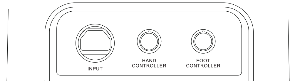
- Power supply and controller connections: Connect the power supply, hand controller, and foot controller to the bed. Voltage and frequency input shall be 110- 120V/60Hz, 220-240V/50Hz. Input ports: INPUT (for power supply), HAND CONTROLLER, FOOT CONTROLLER. (as shown in the right picture)
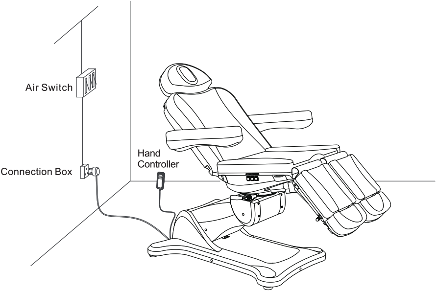
- Connect the plug with the power supply properly. (Details as shown below)
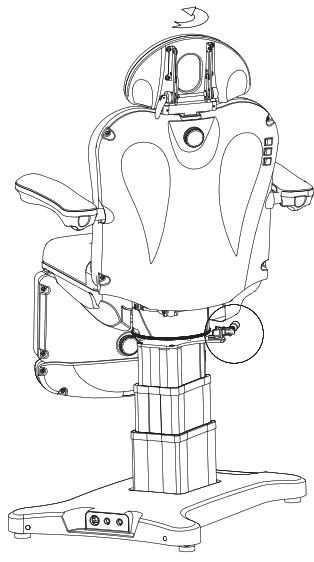
STRUCTURE OF ELECTRIC BEAUTY BED
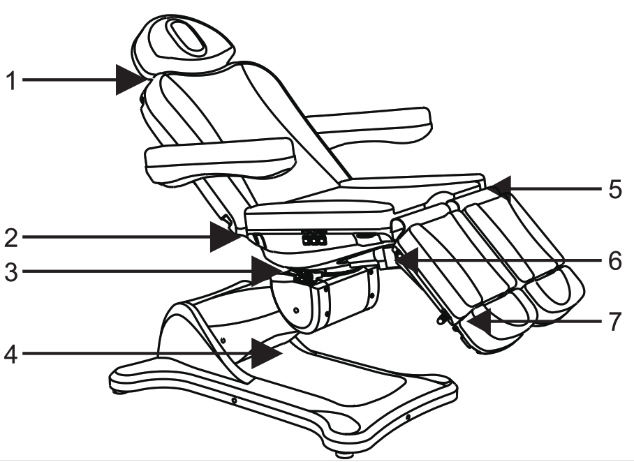
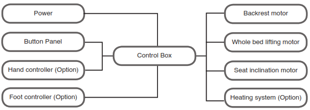
• This beauty bed consists of the control box, motor, hardware, plastic parts, and leather. Among them, the control box is controlling the operation ofthe motors and the hand controller.• This beauty bed includes angle adjustment of the backrest, seat cushion, footrest, and lifting adjustment of the whole bed which is an overalland integral structure. (Details as shown below)
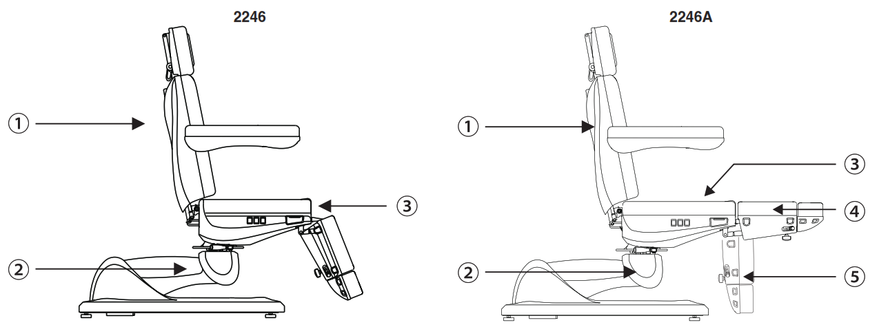
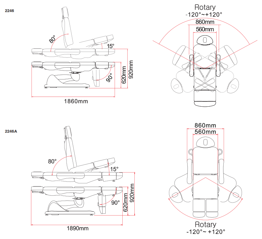
22461. angle adjustment of the backrest2. lifting adjustment of the whole bed3. angle adjustment of the seat4. angle adjustment of the footrest (manual adjustment)
2246A
1. angle adjustment of the backrest2. lifting adjustment of the whole bed3. angle adjustment of the seat4. angle adjustment of the footrest (right) (manual adjustment)5. angle adjustment of the footrest (left) (manual adjustment)
OPERATION INSTRUCTION
Standard Configuration (Button Panel)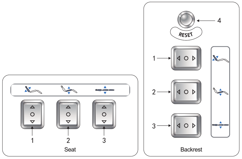
| DESCRIPTION | OPERATION | |
| 1 | Button for backrest adjustment | Press button-up (down), the backrest moves up (down), angle increases (decreases) at a constant speed. |
| 2 | Button for seat adjustment | Press button up (down), seat inclines backward (moves back to horizontal position). |
| 3 | Button for heigh control | Press button-up (down), the seat moves up (down), height increases (decreases) at a constant speed. |
| 4 | One-key reset button | Press the button, the backrest will automatically move up to the maximum, the seat cushion angle will automatically move to flat, the footrest will move down to the minimum, the height of the bed will automatically reach the lowest position. |
1. Optional Configuration (Hand controller)2. Optional Configuration (Hand controller)3. Optional Configuration (Foot controller)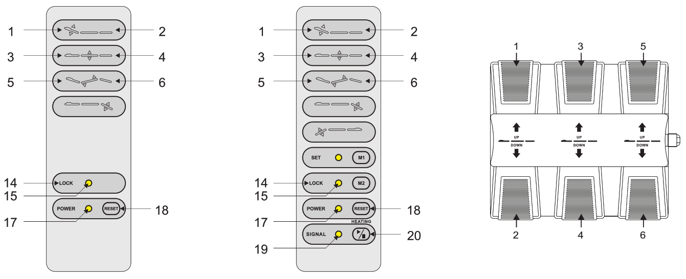
| DESCRIPTION | OPERATION | |
| 1. | Backrest moves up | The backrest goes up smoothly by pressing the button. |
| 2. | Backrest moves down | The backrest goes down smoothly by pressing the button. |
| 3. | The whole bed moves up | The bed goes up smoothly by pressing the button. |
| 4. | The whole bed moves down | The bed goes down smoothly by pressing the button. |
| 5. | Seat cushion up | Seat inclining smoothly by pressing the button. |
| 6. | Seat cushion down | The seat goes flat smoothly by pressing the button. |
| 7. | (The right) footrest moves up | Press the button, the right footrest will move up, its angle will be reduced to a minimum. |
| 8. | (The right) footrest moves down | Press the button, the right footrest will move down, its angle will be moved to the maximum. |
| 9. | (The left) footrest moves up | Press the button, the left footrest will move up, its angle will be reduced to a minimum. |
| 10. | (The left) footrest moves down | Press the button, the left footrest will move down, its angle will be moved to the maximum. |
| 11. | Enter the memory position setting (Option) | The indicator light turns on after pressing the button for 2 seconds, then enter the memory position setting state. |
| 12. | The indicator light of memory setting (Option) | |
| 13. | Memory position setting 1(Option) | 1. Pressing the button “SET” for 2 seconds to enter the memory position setting state, the memory position setting indicator is on. Set the position you need, and pressing the button “Ml”, the actions are set into memory. Exiting the memory position setting state and the indicator goes off.2. Press the button to move to the memory action state automatically. |
| 14. | Safe-lock button | Keep pressing the “safe-lock button” for about two seconds, lighting up the green light around the button, all the buttons can not be operated except the safe-lock button. Keep pressing the safe-lock button for about two seconds again, the green button lights go out, all the buttons return to normal operation status. |
| 15. | Safe-lock button light | |
| 16. | Memory position setting 2
(Option) |
1. Pressing the button “SET” for 2 seconds to enter the memory position setting state, the memory position setting indicator is on. Set the position you need, and pressing the button “M2”, the actions are set into memory. Exiting the memory position setting state an the indicator goes off.2. Press the button to move to the memory action state automatically. |
| 17. | Power indicator | Hand controllers are connected with the power supply properly, the indicator light is on. Otherwise, it won’t light. |
| 18. | One-key reset button | Press the button, the backrest angle will automatically move to the maximum, the seat cushion angle will automatically move to flat, the footrest will move down to the maximum, the height of the bed will automatically reach the lowest position. |
| 19. | The indicator light of heating function (Option) | Pressing the button, the light is on, the heating function works; pressing the button again, the light is off, the heating function stops. |
| 20. | Heating (Option) |
Notes:1. The memory position setting is only available for the models with memory function.2. The heating function is only available for the models with heating functions.3. Different hand controllers should be chosen according to different configurations.
Adjust the instructions
 This product graphic is only for display, the specific product structure please refer to the actual product.
Instruction for Tightening the Braking Block
(This is to tighten the braking block in which the gear is frayed.)
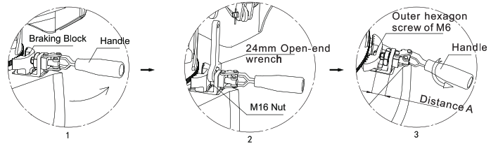 Step 1: Raise backrest to the max. angle, and then loosen the braking block by pushing the handle in the anticlockwise direction as the photo above.Step 2: Hold the handle with your right hand while unscrewing the M16 nut in a clockwise direction with an open-end wrench.Step 3: Press the M6 hexagon screw with the left forefinger to prevent it from rotating, while rotating the handle by 360° anticlockwise with the right hand. This is to increase the distance A.
 Step 4: Keep clamping frame horizontally by holding the handle with the right hand, while screwing the M16 nut with an open-end wrench in the anticlockwise direction.Step 5: Tightening handle in the clockwise direction as the photo above.
Instruction for Replacing Braking Block
(This is to replace the braking block if the gear of the braking block is absolutely worn out and it doesn’t work anymore.)
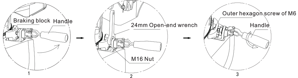
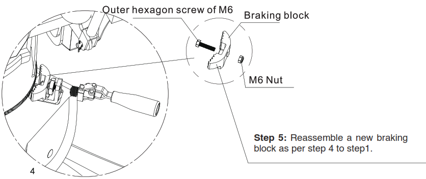
Step 1: Raise the backrest to the max. angel, and then loosen the braking block by pushing the handle in the anticlockwise direction as in the photo above.Step 2: Hold the handle with the right hand, while unscrewing the M16 nut in a clockwise direction with an open-end wrench.Step 3: Press the M6 hexagon screw with the left forefinger to prevent it from rotating, while rotating the handle in a clockwise direction until the handle could be taken out.Step 4: Remove the braking block, and then clamp the hexagon screw with a wrench, while unscrewing the M6 nut with another wrench.
This product graphic is only for display, the specific product structure please refer to the actual product.
TECHNICAL PARAMETERS
| Power | AC 100-120V or AC 220-240V or AC 100-240V, 50/60Hz |
| Maximum Power | 300W |
| Environment Temperature | 0°C–+40°C |
| Relative Humidity | 30%^-90% |
| Lifting Rated Load | 175 KG |
| Package Size | 1360x820x720MM (2246 / 2246A) |
| Net Weight | 79KG (2246 / 2246A) |
| Gross Weight | 92KG (2246 / 2246A) |
MAINTENANCE
 MAINTENANCE
1. After every treatment, please use a neutral reagent to clear the dust, stains on the leather or the plastic cover. This is to prevent premature aging of the leather and plastic cover.2. Please lubricate the moving parts regularly (once a year)
CIRCUIT SYSTEM CONNECTION DIAGRAM
TROUBLESHOOTING
 TROUBLESHOOTING
| THE FAULT PHENOMENON | REASON | SOLUTION |
| 1. The power cord is unconnected or not plugged well | 1. Connect the power cord or plug it well | |
| 2. Poor quality of the hand controller or foot controller | 2. Replace the hand controller or foot controller | |
| 3. Poor quality of the rocker switch | 3. Please contact the maintenance center or supplier for troubleshooting. | |
| 4. Poor quality of the control box | ||
| 5. Rapture of motor tail | ||
| 6. Motor was damaged | ||
| 7. Pressing the button, the bed did not move | 1.Put the movable footrest close to the fixed footrest, make sure the limit switch is closed, and then press the buttons again2. Open the fixed footrest cover and backrest cover respectively, check whether the two ends of the power cord are loose, if the above situation occurs, please reconnect3. If the problem is still not solved after the above operation, please contact the maintenance center or supplier to solve it. | |
| Audio system error | 1. Input/output connection error | 1. Double check the connection of input/output |
| 2. Audio control box error | 2. Replace the defective parts3. If the problem is still not solved, please contact maintenance center or supplier for troubleshooting. | |
| 3. Poor quality of the audio speaker | ||
| Abnormal Sound | 2. Rotating positions (such as hinge, POM sets)are short of lubricating oil | 2. Add lubricating oil |
| 3. Motor quality problems | 2. Add lubricating oil | |
| 3. Replace the motor |
If the problem is still not solved after the above operation, please contact the maintenance center or supplier to solve it.
 Disposal: The product must not be disposed of along with other domestic waste. The users must dispose of this equipment by bringingit to a specific recycling point for electric and electronic equipment.
GIMA WARRANTY TERMSThe Gima 12-month standard B2B warranty applies.
2246A (28025) – 2246 (28045)
Fabbricante / Manufacturer / Fabricant / Fabricante:SILVERFOX CORPORATION LIMITEDNo. 18, 1st TongLe Road, TangXia Town, Pengjiang District, JiangMen City, GuangDong Province, ChinaMade in ChinaImportato da / Imported by / Importé par / Importado por:Gima S.p.A.Via Marconi, 1 – 20060 Gessate (MI) Italy[email protected] – [email protected]
![]()
References
[xyz-ips snippet=”download-snippet”]