Glensound Beatrice B1 & B2 Instruction Manual
OVERVIEW
The BEATRICE range of IP intercoms was designed for broadcast, theatre and professional audio applications.Our Beatrice intercom system utilises the reliable and proven DanteTM network audio transmission protocol to allow real time distribution of uncompressed audio across standard networks. As such the BEATRICE B1 & B2 units are also fully compatible with other manufacturers’ equipment using the DanteTM protocol. The Beatrice B1 & B2 are also both AES67 compliant.All units in the system are designed to be very easy to use for the operator and simple to setup for the technician. They includes all the basic functionality required for small intercom systems and none of the overly complex installation requirements normally associated with large systems.The name Beatrice was chosen for our intercom range as she was the love of Dante Alighieri:‘Dante had fallen in love with another, Beatrice Portinari (known as Bice),whom he first met when he was only nine.’ Source Wikipedia.
B1 & B2 FRONT PANEL LAYOUT
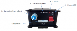
- Talk switchThe front panel speak switches allow the operator to talk to the outgoing talk circuits and hear sidetone. These lever switches can latch on permanently or be momentarily activated depending on which orientation they are held, therefore giving the operator immediate tactile feedback regarding the state of their mic activation.The speak lever keys also double as call switches, whereby a fast double click of the speak lever will send a call signal to the network.The keys are also used during config mode to toggle different features.
- Incoming level adjustThis pot adjusts the volume of the incoming Dante audio for the headphones mix. This pot also controls other parameters when the device is in config mode.
- Mic activity LEDThis Red/Green LED indicates the level of the mic connected to the headset and other parameters in config mode. It will only illuminate during config mode.
- Call LEDThe Call LED(s) indicates the presence of an incoming audio from the Dante network by illuminating solidly when the audio goes above a threshold of -30dBFS. The Call LED(s) will flash for a few seconds upon receiving a call.The Call LED(s) will also flash during config mode to indicate the state of the config mode.
- Power LEDThis LED indicated the power status of the device. This LED also doubles to indicate the status of the config mode.
B1 & B2 REAR PANEL LAYOUT
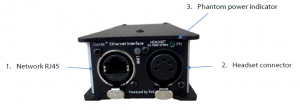
- Network RJ45The Neutrik Ethercon network socket can connect to both Neutrik Etherconand standard RJ45 cables. It is a 100M/bit standard IP network connection. The status LED flashes to show when data is being correctly communicatedwith the attached switch.This is also how the device is powered using a Power Over Ethernet (PoE) source. The PoE source can be a mid-span source or a network switch with PoE
- Headset connectorHeadphone outputThis 5 or 4 pin XLR socket accepts headphones from 30 to 1000 Ohms. It has a unique headphone amplifier that allows it to provide the correct outputlevel regardless of the headphone impedance and it can also have mono headphone jacks connected with no adverse effect. Microphone InputThis is a balanced microphone input sharing the connector with the headphone output. It can accept dynamic and condenser microphones and phantom power (12v).Refer to the end of this manual for wiring information.
- Phantom power LEDThis green LED will illuminate to indicate if +12v phantom power is active or disabled.
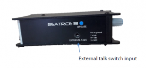
SIDE PANEL LAYOUT
- External control inputThis 3.5mm (TRS) jack connector allows an external switch to trigger the talk functionality. The switch must connect the Tip and Ring to Sleeve; bridging tip (T) to sleeve (S – GND) will activate the channel 1 circuit and bridging ring (R) to sleeve (S – GND) will activate the channel 2 circuit (if using a Beatrice B2).
- CONFIG MODEThe Beatrice B1 and B2 have a configuration mode that allows the user to adjust certain settings and parameters of the device.To enter config mode, the UPDATE button on the left side panel must be held down for 3 seconds.Config mode is linear, where settings are changed in groups that are cycled through
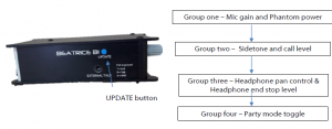
Once config mode is entered, the LEDs will rapidly flash to indicate which group of the config mode the device is currently in. To cycle through to the next group, simply press the UPDATE button once.Note: In config mode, audio from the Microphone input is only transmitted to Dante during group one (where mic gain is adjusted), regardless of the talk switch position or party mode status. Audio from Dante is not silenced and continues as normal whilst in config mode.
- Power LED and Call LED flash – Mic gain and Phantom power controlIn this first config mode, turning pot one will adjust the Microphone gain, whilst pressing the talk switch will toggle +12v phantom power on or off.On the B2 this is done by pressing both talk switches at the same time.The Red/Green LED “Mic” LED will illuminate to indicate mic gain level. Green is acceptable level, orange indicates that the level is a little high and red indicates close to overloading the input and clipping.
- Call LED flashes – Sidetone and call chime level In the second config mode, activating talk switch one will allow adjustment of the call alert tone and the call send tone by turning pot one.NOTE: When the call level is turned fully off and muted, calling functionality is fully disabled. When the talk switch is off, sidetone level is adjusted when turning pot one.
- Power LED flashes – Headphone pan control and Headphone end stop levelIn the third config mode, pot one and pot two (if using a B2) will control the headphone panning of the respective incoming Dante audio.During this config mode, pressing the talk switch will toggle the headphone level end stop value. The mic activity led will show the state; Red indicates the minimum headphone volume level is -20dBu (from 0dBu input) and Green indicates that the headphone volume is fully off when the potentiometer is at minimum.On the B2 this is done by pressing both talk switches at the same time.
- No LEDs flash – Party mode settingParty mode is toggled by pressing the talk switch. The mic activity LED will indicate if party mode is enabled or disabled by illuminating either green or red.On a B2, the mic activity LED will illuminate orange and the respective red channel call LEDs will flash to indicate if party mode is active. Pressing down the talk switches will independently enable or disable party mode for each channel.
To leave config mode, simply push the UPDATE button again to return to normal usage. The device will exit config mode automatically after a few minutes.Normal mode is the only state in which the PWR LED will be on solidly.Note: In config mode, the pots will only change a value if the user turns them far enough away from their current position. This is to avoid the levels being changed without the users desire every time the device cycles to the next config group.
RESET TO FACTORY DEFAULT SETTINGS
To reset the device to a base default configuration, make sure both talk switches are set to the off position (middle) and simply hold down the update button continuously for 11 seconds. The device will illuminate all LEDs for 1 second and play a pip tone out of the headphones on success.The default settings are as follows:Mic gain level 23 / 31Sidetone level 8 / 31Call ring level 10 / 31Panning – All centralHP Volume end stop set to -20dBu (from 0dBu in)Phantom power offParty mode off on all channelsAlternatively, if you activate talk switch 1 whilst holding down the update button for 11 seconds then a different base setting will be applied.The alternate setting is as follows:Mic gain level 23 / 31Sidetone level 0 / 31Calling fully disabledPanning – All centralHP Volume end stop set to -INFPhantom power offParty mode off on all channels
CALLING OTHER BEATRICE DEVICES
The Beatrice uses a standardised calling method that allows it to send and receive calls to and from other Beatrice devices. A 20kHz tone is sent to alert the recipient of an incoming call.When the Beatrice B1 or B2 receives a call, the channel specific call led will flash and the device will ring for a few seconds.To send a call to another device, quickly double press the talk switch for the channel you want to call. An audible beep will sound when a call is successfully sent. There is a 5 second cooldown after sending a call before another call can be sent.Note: If you have muted the calling volume in config mode then all call functionality is disabled. This does not mean that you cannot send and receive normal audio, it means that the device will not send a 20kHz tone or react to receiving a 20kHz tone
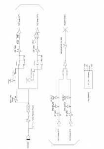
AUDIO BLOCK DIAGRAM (analogue representation of digital circuits) Audio Circuits TO and FROM Dante/ AES67
CONNECTING THE BEATRICE UNITS TO A DANTE NETWORK
The Beatrices are network audio devices utilizing the reliable and versatile Dante audio over IP protocol. Dante is a proprietary system (although very widely used) the originators of which are Audinate.The information below is only meant as a very basic guide. Full details of the power of Dante network audio and instructions for using it can be found at www.audinate.com
Getting Dante Controller
If you are connecting the Beatrice to a new Dante network the first thing you will need to do is to get the free Dante controller software from Audinate.This can be downloaded by visiting Audinate’s web site at www.audinate.com
Connecting Beatrice D8 To the Network
The Beatrice can be connected to the network that you are going to use for your audio distribution simply by plugging in to the RJ45 network connections on the rear. Once connected to the network it will be possible to see the Beatrice from within the Dante controller and route its’ audio circuits.
Audio Over IP Network
We strongly recommend that you consider your network topology carefully and would not recommend sharing broadcast audio and general data on the same network.For more details of audio over IP network structure please visit www.audinate.com
Running Dante Controller
At the time of writing this manual the Dante Controller looks as per the screenshot below:
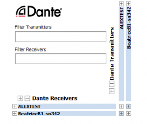
The Beatrice B1 and Beatrice B2 will have been named at the factory during test to allow them to be identified by the Dante controller.The format used for the factory name is:BeatriceB1-snXXX’Where ‘BeatriceB1’ refers to the Glensound product i.e. BeatriceB1.The ‘–snXXX’ refers to the serial number of the BeatriceD8 which can be found printed on the rear or side of the unit.The unit may be renamed in Dante controller by opening the ‘Device view’ window and selecting BeatriceB1 in the drop-down menu. Go to the ‘Device Config’ tab and change the name with the Rename Device box.Note if you upload a new DNT file or clear the devices config then the name will change to BeatriceB1-xxXxXx whereby the ‘X’s refer to the devices MAC address.
Dante Controller TIP
If you have never run Dante controller before then make sure that on the bottom left of the Dante controllers’ screen ‘P’ or ‘S’ is next to a green square as this indicates that it is connected to a network. By clicking ‘P’ or ‘S’ a pop up box opens to allow you to set what network interface the controller is using.
Device not showing up in Dante Controller
If your DanteTM device does not show up in DanteTM Controller then the most likely issue is that the device’s IP Address is not appropriate for your network.A) It maybe that the device is set to obtain an IP address automatically using DHCP (this is the default configuration) and your network is setup for fixed IP addresses only and does not have a DHCP server.B) It maybe that the device has had a fixed IP address assigned but that this address is not suitable for your network.
The solution to both scenarios is basically the same.
- You must connect your DanteTM device directly to the Ethernet port of your computer using an Ethernet cable.
- Make sure that your computer is set to ‘Obtain an IP address automatically’
- After a few minutes the DanteTM device should now appear in DanteTM Controller.
- Double click the device name to open up device view.
- Open up the ‘Network Config’ tab
- Either turn on ‘Obtain an IP Address Automatically’ or correctly configure the ‘Manually configure an IP Address’ options for your network.
- Click on ‘Apply’ to confirm the new settings, then disconnect the computer and reconnect the DanteTM device to your network.
AES67 MODE
The Beatrice uses a chipset from Audinate called the Ultimo for its network audio interface. Audinate are the company behind DanteTM and as such the primary network audio protocol is Dante, however Audinate have enabled their chip to comply with AES67 and therefore the Beatrice can be set to AES67 mode for interaction with other AES67 devices.Please note however that Glensound are relying on Audinate’s AES67 interface and are unfortunately not able to provide full AES67 support for the unit. AES67 support should be sought directly from Audinate.Turning On AES67 ModeIf you want to use your Beatrice on an AES67 network and it has not been set to AES67 mode then this can be set in Dante controller by double clicking the Beatrice to open the Device View window where you will find an AES67 tab to enable AES67 support.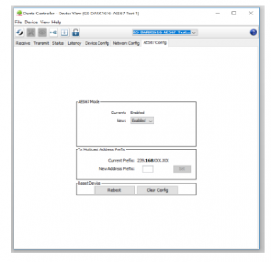
Once the AES67 drop down box has been enabled you’ll have to reboot the Beatrice for the change to take effect. After the reboot go back to the AES67 tab and set the multicast prefix address to one that is suitable for your newtork.
Sending AES67 Audio
To transmit AES67 audio to the network a multicast flow must first be setup.This is done by selecting the ‘Create New Multicast Flow’ Icon in the Device View.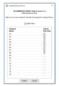
Tick the AES67 Flow check box, then select up to 8 channels to be included in the flow then click ‘Create’Once set the flows can be seen in the transmit tab of the device view.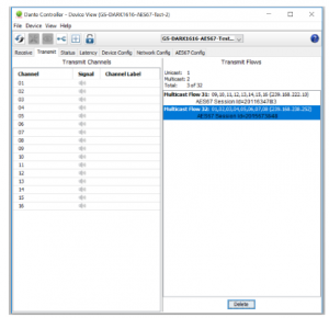
Receiving AES67 Audio
Once a compatible AES67 stream is detected on the network by Dante Controller the AES67 flows will appear in the Dante Transmitters section in the Routing tab.
AES67 RestrictionsAES67 flows can only be generated with the following constraints:
- Multicast Only
- Non-redundant
- Destination address in range 239.nnn.0.0 to 239.nnn.255.255 (239.nnn/16), port 5004
- 48kHz sampling rate
- 24 bit linear (L24) encoding
- 1 msec packet time
- Up to 8 channels per stream
Received AES67 flows have the following constraints:
- Multicast Only
- Non-redundant
- Destination address in range 239.nnn.0.0 to 239.nnn.255.255 (239.nnn/16), port 5004. Must match destinatio address range.
- 48kHz sampling rateL16 or L24 encoding
- 125usec, 250usec, 333usec, 1 msec packet time
- Up to 8 channels per stream
UPDATING FIRMWARE
Equipment needed
- A windows based PC
- USB Type A to Micro B cable
- A copy of ‘DfuSe Demo’ software
- The latest firmware from Glensound
- A Beatrice B1/2 and a PoE source
Instructions
- Download and install DfuSE Demo‘DfuSE Demo’ is a firmware updating tool that is required for loading new firmware on to the STM32 Device.It can be downloaded from the STMicroelectronics website found here: https://goo.gl/AbzhsA. It is the file named “STSW-STM32080”.Once you have downloaded this file you will need to extract the .exe “DfuSe_Demo_V3.0.5_Setup.exe”, then run and install it.
- Download firmwareThe latest firmware for the Beatrice B1/2 can be found on the Glensound website, under the respective product page. Once you have downloaded the file, place it in a folder or location of your choice.
- Connect To A PCConnect the Beatrice B1/2 to the PC via the USB cable. The micro USB connector is located on the side panel of the Beatrice B1/2.
- Firmware update preperation
To prepare the Beatrice B1/2 for a firmware update;
- Make sure the device is connected with USB
- Press and hold down the UPDATE button
- Power on the unit
- Release the UDPATE button after a few seconds Your PC should make an audible sound when this process is successful as windows is detecting a new USB device.
- Loading the firmwareNow open DfuSe Demo. If the Beatrice B1/2 successfully entered DFU mode then it will appear as ‘STM Device in DFU Mode’ under the ‘Available DFU Devices tab’. Figure 3 Device successfully recognisedNow the .dfu file needs to be selected so that DfuSe Demo knows the correct firmware to put on to the Beatrice B1/2.Click choose and then select the .dfu file that you downloaded from the Glensound website. This will be located in your downloads folder by default.If the file loads successfully then it will read along the bottom ‘File correctly loaded’.
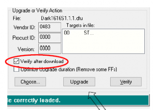
- Click choose and then select the .dfu file that you downloaded from the Glensound website. This will be located in your downloads folder by default.If the file loads successfully then it will read along the bottom ‘File correctly loaded’.Click yes to proceed.The progress bar along the bottom will show the status of the operationIf the operation was successful, DfuSe Demo will report that “Targery 00: Verify Successful!”.You may also see that it will report how much data was successfully transferred.
- Final stepsNow click “Leave DFU mode” to finish the procedure.You may now disconnect the USB cable and continue to use the Beatrice B1/2 with the freshly updated firmware
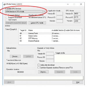 Figure 3 Device successfully recognisedNow the .dfu file needs to be selected so that DfuSe Demo knows the correct firmware to put on to the Beatrice B1/2.
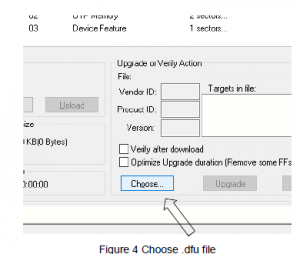 Click choose and then select the .dfu file that you downloaded from the Glensound website. This will be located in your downloads folder by default.If the file loads successfully then it will read along the bottom ‘File correctly loaded’.
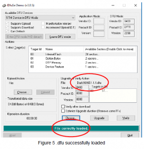
 Click yes to proceed.
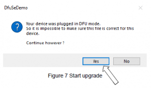 The progress bar along the bottom will show the status of the operation
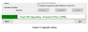 If the operation was successful, DfuSe Demo will report that “Targery 00: Verify Successful!”.You may also see that it will report how much data was successfully transferred.
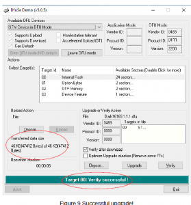
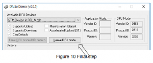 You may now disconnect the USB cable and continue to use the Beatrice B1/2 with the freshly updated firmware
UPDATING THE ULTIMO CHIPSET
The Ultimo Chipset is a device supplied by Audinate that does most of the processing for the actual Dante/ AES67 network audio streams. There is one Ultimo Chipset in each Beatrice. We supply special code (a .dnt file) that sets up/ initiates the Ultimo Chipset and makes it work in particular way that is compatible to the Beatrice.
Finding Out Current Installed Version
Using Dante® controller double click on the Beatrice device name in the routing tab to open the Device View box.Ion the Device View box open the Status Tab.The ‘Product Version:’ shows the currently installed version of Ultimo Chipset dnt code.
Finding Out What The Latest Available Version Is
Go the Beatrice’s web page at Glensound.com and open the ‘Firmware Latest Version’ Tab.This will give both the latest version numbers/ file names and also the location to download the file from.
Updating the device
The firmware that runs in the Ultimo Chipset is updated using Audinate’s Firmware updating tool. The updating tool and a user guide can be downloaded from Audinate’s website:https://www.audinate.com/products/firmware-update-manager
NOTE:
Please note we strongly advise that when you do the update that only your PC and the Dante device that you want to update are on the network to save accidently updating the wrong Dante device.
WIRING INFORMATIONXLR & JACK Wiring
- 5 PIN XLR AUDIO PINOUTS: MATE/ NEGATIVE/ MIC –
- INPHASE/ POSITIVE/ MIC +
- GROUND/ EARTH
- HEADPHONE LEFT
- HEADPHONE RIGHT
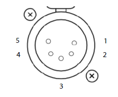
4 PIN XLR AUDIO PINOUTS:
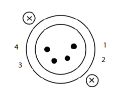
- MIC GND/ MIC –
- INPHASE/ POSITIVE/ MIC +
- HEADPHONE GND
- POSITIVE/ HEADPHONE +
Read More About This Manual & Download PDF:
References
Audinate – Maker of Dante, Pro AV\’s Leading Networking Technology
STSW-STM32080 – DfuSe USB device firmware upgrade (UM0412) (replaced by STM32CubeProgrammer) – STMicroelectronics
Glensound – The Home of Dante & AES67 Audio Networking
Firmware Update Manager | Audinate
Glensound – The Home of Dante & AES67 Audio Networking
Audinate – Maker of Dante, Pro AV\’s Leading Networking Technology
[xyz-ips snippet=”download-snippet”]