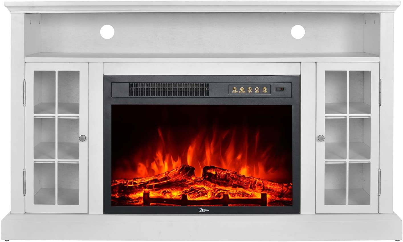
GMHome Fireplace Model # EF-30AKF Instruction Manual
Choose GMHome Fireplace, Enjoy Gorgeous & Magnificent Home
Any questions or problems, just find us at: [email protected]

General Assembly Guidelines
I. Ensure that all parts and hardware are available before beginning assembly.
II. Follow each step carefully to ensure the proper assembly of this product.
III. Two people are recommended for ease in the assembly of this product.
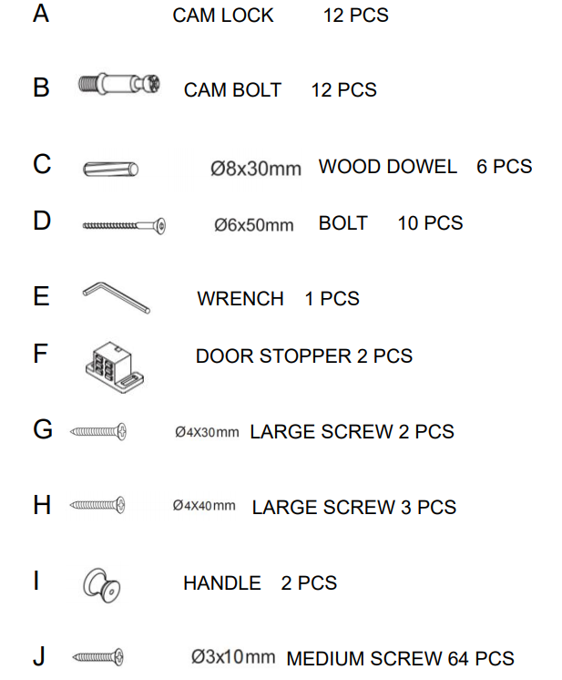
IV. The four main types of hardware used to assemble this product are: wood dowels, cam bolts and locks, bolts and screws.
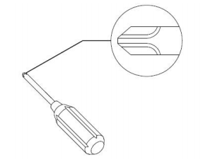
VI. A Phillips head screwdriver is required for the assembly of this product.
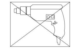
VII. Power tools should not be used to assemble this product.
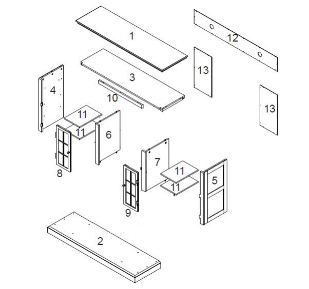
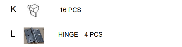
Parts List
Hardware List
Assembly Instructions
Fig.1

“Please do not over tighten cam bolts, please stop when you feel tight”
- Screw Cam Bolts B into holes on part 1.
Fig.2
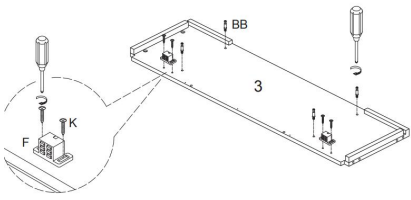
- Screw Cam Bolts B into holes on part 3.
- Fix 2 pieces of door stopper F on part 3 by medium screw K.
Fig.3

- Connect part 10 to part 3 by 2 pcs wood dowel C first.
- Connect part 10 to part 3 by 3 pcs large screws H.
Fig.4
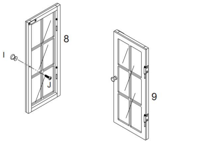
- Install Handel I onto part 8 and part 9
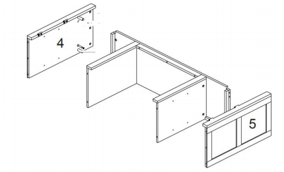
Fig.5
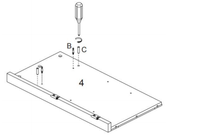
- Screw Cam Bolts B into holes on part 4.
- Insert wood dowel C into holes on part 4.
Fig.6
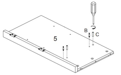
- Screw Cam Bolts B into holes on part 5.
- Insert wood dowel C into holes on part 5.
Fig.7
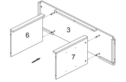
- Connect part 6 and part 7 to assembly unit on Fig.3 by inserting Cam Bolts into corresponding holes until Base.
Fig.8
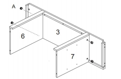
- Tighten by rotating Cam Locks A clockwise with screwdriver.
Fig.9
- Connect assembly unit on Fig.5 and assembly unit on Fig.6 to assembly unit on Fig.8
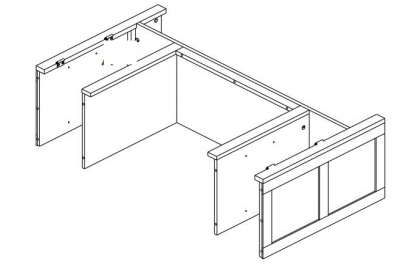
Install by screws
Fig.11
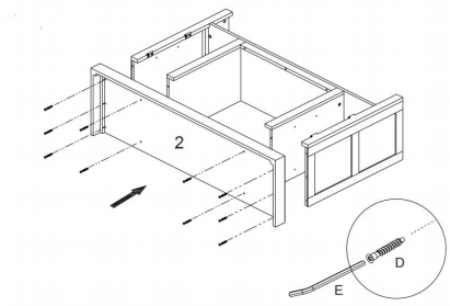
- Connect part 2 to assembly unit on Fig.11 by Bolts D.
- Tighten with wrench E.
Fig.12
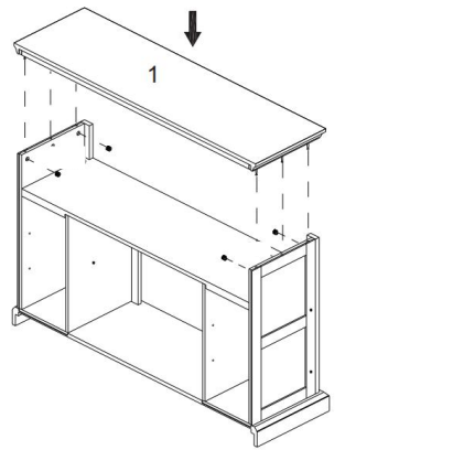
- Connect assembly unit on Fig.1 to assembly part on Fig.11 by inserting Cam Bolts B which on part 1 into corresponding holes until Base.
- Tighten by rotating Cam Locks A clockwise with screwdriver.
Fig.13
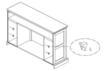
- Insert hardware L into holes on assembly unit on Fig.12.
Fig.14
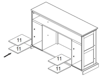
- Install parts 11 onto hardware L.
Fig.15

- Connect part 12 and part 13 to assembly unit on Fig.14 by medium screw K.
Fig.16

- Install the door – part 8 and part 9 on the assembly unit on Fig.15.
Fig.17
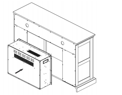
- Install the firebox into the fireplace mantel.
Choose GMHome Fireplace, Enjoy Gorgeous & Magnificent Home
Any questions or problems, just find us at: [email protected]
[xyz-ips snippet=”download-snippet”]