Godox High Speed Sync Flash LED Light Instruction Manual
Foreword
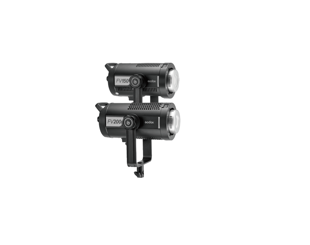
Thank you for purchasing this Godox Product!Flash Video Light FV series add flash functions based on the traditional LED light. FV series can be served as a flash, as well as an LED light. With strong power, abundant functions and 8 special effects modes, it can achieve creative shooting easily.
Main Features:
- Can both serve as a flash and an LED light.
- The light brightness of the flash is four times of LED light’s, which increases the freezing ability of instantaneous action.
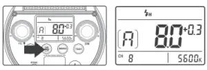
- Supports 1/8000s high-speed sync function when being used as flash.
- Over 10 continuous flashes per second and 8 continuous flashes per second in high-speed sync mode in 1/2 power output.
- Built-in Godox 2.4G wireless X system, compatible with cameras of multiple brands.
- With stable light source and 0% to 100% precise light adjustment when being used as LED light.
- With 8 FX special effects mode to simulate various of shooting scene.
- With 16 groups and 32 channels wireless control.
- With U-type bracket to adjust different angles easily.
- Bowens-mount enables to install various of accessories.
- Clear LCD display.
- Excellent heat dissipation.
Warning
 Warning
![]() Always keep this product dry. Do not use in rain or in damp conditions.
Always keep this product dry. Do not use in rain or in damp conditions.![]() Do not disassemble. Should repairs become necessary, this product must be sent to an authorized maintenance center.
Do not disassemble. Should repairs become necessary, this product must be sent to an authorized maintenance center.![]() Keep out of reach of children.
Keep out of reach of children.![]() As this product do not have waterproof function, please take measures of waterproof in rainy or damp environment.
As this product do not have waterproof function, please take measures of waterproof in rainy or damp environment.![]() Do not use the flash unit in the presence of flammable gases, chemicals and other similar materials. In certain circumstance, these materials may be sensitive to the strong light emitting from this flash unit and fire or electromagnetic interference may result.
Do not use the flash unit in the presence of flammable gases, chemicals and other similar materials. In certain circumstance, these materials may be sensitive to the strong light emitting from this flash unit and fire or electromagnetic interference may result.![]() As this product has built-in lithium battery, do not disassemble, impact, squeeze or put it into fire. If serious bulge occurs, please do not use. Do not use or store the product if the ambient temperature reads over 40°C. Please charge the product with specialized charger and correctly operate it within the defined voltage and working temperate according to the instruction manual.
As this product has built-in lithium battery, do not disassemble, impact, squeeze or put it into fire. If serious bulge occurs, please do not use. Do not use or store the product if the ambient temperature reads over 40°C. Please charge the product with specialized charger and correctly operate it within the defined voltage and working temperate according to the instruction manual.
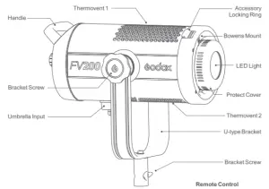
Body
Main Body
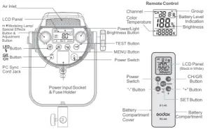
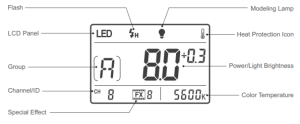
LCD Panel
LCD Panel
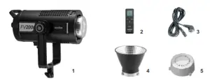
Included Items
1. Flash video light2. RC-A6 Remote control3. Power cord4. Reflector for Bowens mount LED light5. Lamp cover
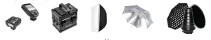
Separately Sold Accessories
The product can be used in combination with the following accessories sold separately, so as to achieve best photography effects: XPro, X2 or XT32 remote control, Power Inverter, Softbox, Photographic Umbrella, Light Stand, Barndoor, Snoot, etc.
Power Connection
Use the power cord to connect the flash to an AC power source and turn on the power switch.
Operation
Flash Setting
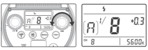
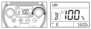
ButtonThis button can be pressed to switch LED mode or flash mode. Short press the button and LED will be displayed, which means the light can be used as an LED. When is displayed, the light can be used as a flash.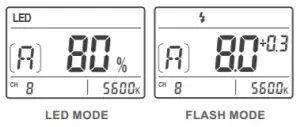
Power AdjustmentIn flash mode, the flash power can be adjusted by light brightness adjustment button from 1/16 to 1/1 or 6.0 to 10. And the power output will be clearly displayed on the LCD Panel. “OF” on the display indicates that the flash triggering function is turned off. Press the Test button to discharge power when the flash output is adjusted from high to low.
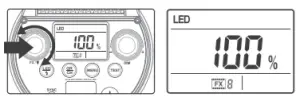
Light Brightness AdjustmentIn LED mode, the light brightness of LED light can be adjusted by light brightness adjustment button from 0% to 100%. And the light brightness will be clearly displayed on the LCD Panel.
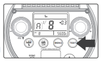
Test ButtonTo fire the flash without taking a picture, press the test button. It can also help adjust the flash output and light brightness when combined with the light brightness adjustment button. Hold down the light brightness and turn on the light, the version will be displayed on the LCD panel and this operation can also be used to restore factory setting.
MENU ButtonPress the Menu button to enter custom setting area. Custom Function Setting
| Custom FunctionSigns | Functions | Setting Signs | Settings & Descriptions | Restrictions |
| F1 | Wireless ID | OF | Off ID | No |
| 01~ 99 | Choose any figure from 01~99 | |||
| F2 | Power output
display mode |
1/P | Display power in the form of fractions | Flash mode |
| P.P | Display power in the form of fraction decimal |
GR/CH ButtonShort press the GR/CH button can adjust the wireless groups. When the group icon on the LCD panel is blinking, turn the light brightness adjustment button to set the groups. Long press the GR/CH button to adjust the wireless channels. When the channel icon on the LCD panel is blinking, turn the light brightness adjustment button to set the channels.
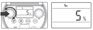
Modeling Lamp/Special Effect ButtonModeling lamp ON/OFF: In flash mode, press the modeling lamp/special effects button to turn on or off the modeling lamp. When modeling lamp is on, turn the modeling lamp/special effects button to adjust the light brightness of modeling lamp from 5% to 100%.
Special Effects ON/OFF: In LED mode, press the modeling lamp/special effects button, and the special effects will be on or off. Turn the modeling lamp/special effects button to choose from the eight special modes.
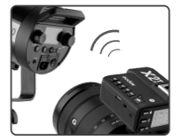
Flash Mode2.4G Wireless controlIn flash mode, FV series has 2.4G wireless receiving functions. Purchase Godox X series flash trigger e.g. X1, X2, XPro series and XT 32 flash trigger to wirelessly control FV series’ power, modeling lamp’s on/off and triggering.
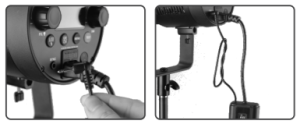
Sync TriggeringThe sync cord jack is a Φ3.5mm plug. Insert a trigger plug here and the flash will be fired synchronously with the camera shutter.
Wireless Control in LED ModeWith 2.4G wireless system, FV series have remote grouping and control function. Up to 16 groups of LED lights can be controlled. 32 channels and 100 wireless IDs are available with strong anti-interference capability. Please set the channels and groups of LED light to the same as those of RC-A6 remote control before usage.Adjusting Channel/Group with the Remote Control
- Press the CH/GR button and the group icon blinks. Press the“-”“+”button to choose a group (A to F, 0 to 9).
- Press the CH/GR button twice and the channel icon blinks. Press the“-”“+”button to choose a channel (1 to 32).
Adjusting ID with the Remote Control
- Double click the CH/GR button and press the“-”“+”button to choose ID from OFF or 0 to 99.
Adjusting Light Brightness with the Remote Control
- Press the“-””+“button to adjust the light brightness.
Adjusting Color Temperature with the Remote Control
- Press the SET button of the remote control and the color temperature icon blinks. Press the“-”“+”button to adjust the color temperature.
Remote control reset: press down “-” and “+” button simultaneously to reset.
Note: The wireless signal can be received only when the controller of LED light is powered on.
Setting color temperature rangeThe factory setting of remote control’s color temperature range is 2500-10000K. In order to use remote control conveniently, color temperature range settings are added: when the remote control is off, hold down the SET button and turn it on to enter color temperature adjusting interface. Press CH/GR button to switch the lowest and highest color temperature value and press “-” or “+” button to change the value. Press the SET button to confirm it.
LED Special Effects ModeIn LED mode, 8 FX special effects mode can be set to simulate various of shooting scene and achieve creative shooting.
| Display | FX1 | FX2 | FX3 | FX4 | FX5 | FX6 | FX7 | Fx8 |
| Scene | Flash1 | Flash2 | Flash3 | Storm1 | Storm2 | Storm3 | TV | Broken bulb |
The Reason & Solution of Not Triggering in Godox 2.4G Wireless
1. Disturbed by the 2.4G signal in outer environment (e.g. wireless base station, 2.4G wifi router,Bluetooth, etc.)→ To adjust the channel CH setting on the flash trigger (add 10+ channels) and use the channel which is notdisturbed. Or turn off the other 2.4G equipment in working.2. Please make sure that whether the flash has finished its recycle or caught up with the continuousshooting speed or not(the flash ready indicator is lighten) and the flash is not under the state of overheatprotection or other abnormal situation. →Please downgrade the flash power output. If the flash is in TTL mode, please try to change it to M mode(apreflash is needed in TTL mode).3. Whether the distance between the flash trigger and the flash is too close or not→Please turn on the “close distance wireless mode” on the flash trigger (<0.5m):X1, X2 and XPro series: press the test button and hold on, then turning it on until the flash ready indicatorblinks for 2 times.XPro series: Set the C.Fn-DIST to 0-30m.4. Whether the flash trigger and the receiver end equipment are in the low battery states or not→Please replace the battery(the flash trigger is recommended to use 1.5V disposable alkaline battery).
Technical Data
| Flash Video Light | FV150 | FV200 |
| Power Supply | AC100V-240V (50/60Hz) | |
| Power | 150W | 200W |
| Color Temperature | 5600±200K | |
| 100% Light Brightness(LUX,1M) | ≈58000 | ≈74000 |
| CRI ≈ | 96 | |
| TLCI ≈ | 97 | |
| Light Brightness Range | 10%-100% | |
| Operation Temperature | -10°C ~ 40°C | |
| Power Output | 1/16-1/1 or 6.0-10.0 | |
| Channel | 32 | |
| Group | 16(A, B, C, D, E, F, 0-9) | |
| Dimension
(not included a standard reflector) |
34x20x16cm | 36.7x20x16cm |
| Net Weight | 3.13Kg | 3.24Kg |
| Remote Control | RC-A6 |
| Power Supply | 3.0V(AAA*2)(not include) |
| Wireless Frequency | 2.4GHz |
| Distance (emptiness) | 50m |
| Channel | 32 |
| Group | 16 groups(A-F, 0-9) |
| Standby Time | Over one year |
| Operation Temperature | -10°C ~ 40°C |
| Dimension | 120*38*15mm |
| Net Weight | 30g |
FCC Warning
This device complies with part 15 of the FCC Rules. Operation is subject to the following two conditions: (1) This device may not cause harmful interference, and (2) this device must accept any interference received, includinginterference that may cause undesired operation. Any Changes or modifications not expressly approved by the party responsible for compliance could void the user’s authority to operate the equipment.Note: This equipment has been tested and found to comply with the limits for a Class B digital device, pursuant to part 15 of the FCC Rules. These limits are designed to provide reasonable protection against harmful interference in a residential installation. This equipment generates uses and can radiate radio frequency energy and, if not installed and used in accordance with the instructions, may cause harmful interference to radio communications. However, there is no guarantee that interference will not occur in a particular installation. If this equipment does cause harmful interference to radio or television reception, which can be determined by turning the equipment off and on, the user is encouraged to try to correct the interference by one or more of the following measures:
- Reorient or relocate the receiving antenna.
- Increase the separation between the equipment and receiver.
- Connect the equipment into an outlet on a circuit different from that to which the receiver is connected.
- Consult the dealer or an experienced radio/TV technician for help.
 report this ad
*RF warning:This equipment complies with FCC radiation exposure limits set forth for an uncontrolled environment. This equipment should be installed and operated with minimum distance 20cm between the radiator & your body.
Read More About This Manual & Download PDF:
References
[xyz-ips snippet=”download-snippet”]