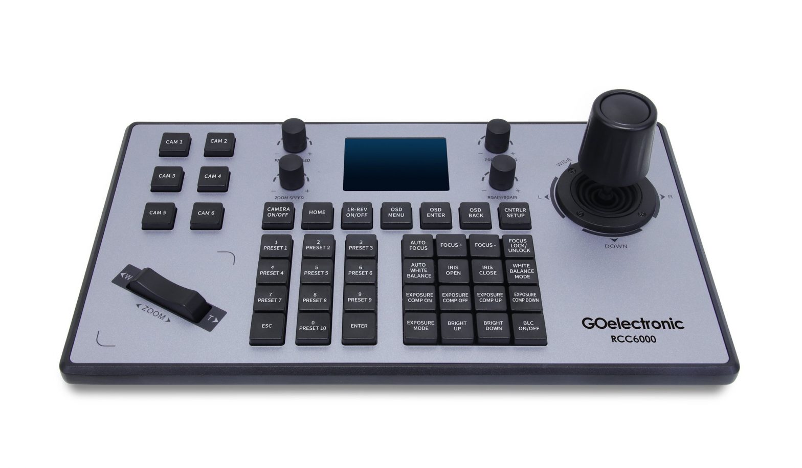
GOelectronic Pan/Tilt/Zoom Camera Controller RCC6000
The contents in this manual may be updated without notice.
PRODUCT FEATURES
- Supports network/IP and analog control
- Supports VISCA, VISCA over IP, ONVIF, PECLO-P and PELCO-D protocols
- Variable speed 4D joystick controller
- Supports web interface to add camera configuration parameters
- Supports control of up to six cameras via shortcut keys (CAM 1, CAM 2, CAM 3, etc.)
- Supports standard POE power supply
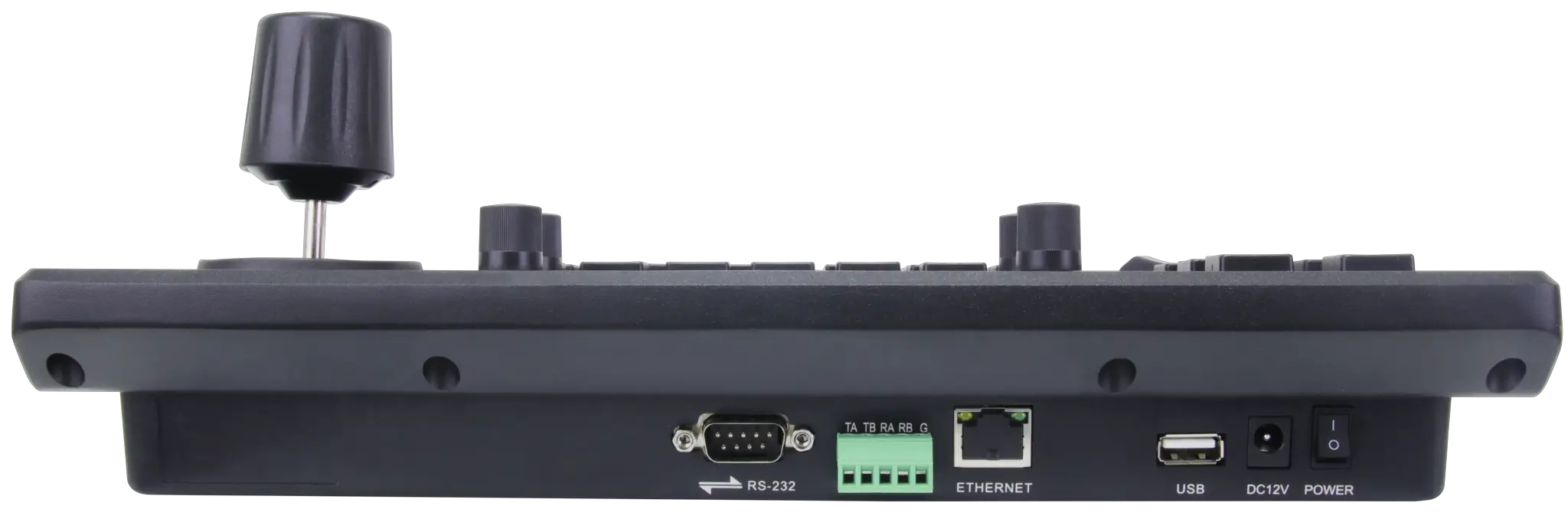
CONTROLLER INTERFACE
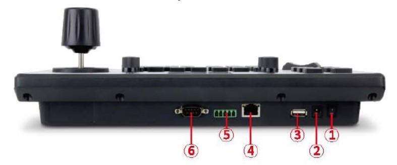
- POWER – Power switch
- DC12V – Power interface
- USB – Used for updating joystick firmware
- Ethernet – Network interface
- RS422
- RS232
PRODUCT CONNECTION DIAGRAM
NETWORK CONNECTION
Network Mode: Network VISCA, ONVIF Connection Diagram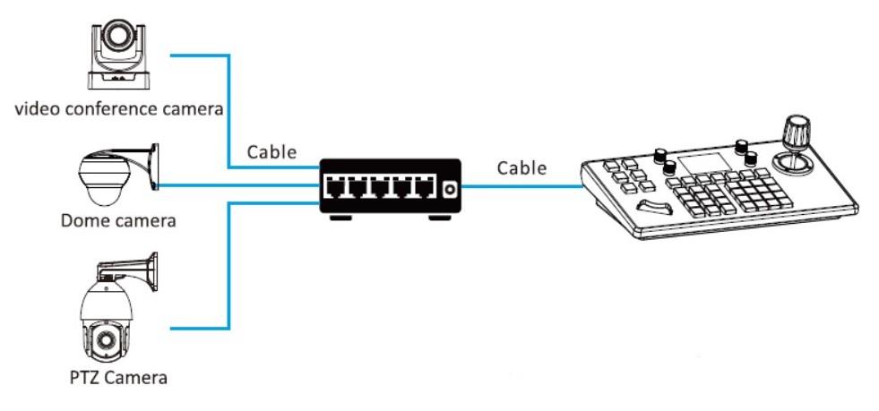
Camera and controller need to be connected to the same LANConnect the camera and controller to the same LAN and confirm that their IP address is in the same network segment. For example, 192.168.1.123 and 192.168.1.111 belong to the same network segment while 192.168.1.123 and 192.168.0.125 do not. If the controller and camera do not belong to the same network segment, you will need to modify the controller or camera IP address at this time. The controller gets its IP address dynamically.
ANALOG CONNECTION
Analog Mode: RS484 Connection Diagram

Control Output: RS485+ of camera connects to Ta of controller and RS485- of camera connects to Tb of controller
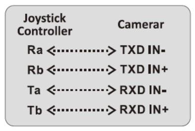
ANALOG CONNECTION
Analog Mode: RS422/RS232 Connection DiagramsUsing RS422 bus connection, the third pin Ra of the controller connects to TXD IN- of the camera, the fourth pin Ta of the controller connects to the RXD IN- of the camera, the second pin Tb of the controller connects to the RXD IN- of the camera.
Using RS232 connection, the first pin RXD of the controller (10-pin terminal) connects to TXD of the camera, the second pin TXD of the controller connects to RXD of the camera, the third pin of the controller connects to the GND of the camera. 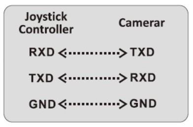
CONNECTION BETWEEN CAMERAS
The output of camera 1 connects to the input of camera 2, the output of camera 2 connects to the input of camera 3, and so on.
KEYBOARD FUNCTIONS
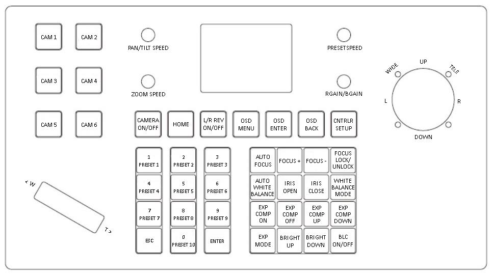
[CAM 1] – [CAM 6]Camera selection keys.Once you have added cameras following the instructions below, you can use the camera selection keys to select the camera you would like to control based on the Address / Number you previously assigned.[CAMERA ON/OFF]Press and hold to power on/off camera (hold until camera powers on/off). When powering on, camera must cycle thru full rotation before it will respond to the controller.[HOME]Return camera to the ‘Home’ position[LR-REV ON/OFF]Change direction of controller; camera moves in same/opposite direction as joystick.[OSD MENU]Display camera’s on-screen display settings/functions menu.[OSD ENTER]Confirm/select within camera OSD menu[OSD BACK]Go back to previous screen within camera OSD menu[CNTRLR SETUP]Access controller settings menu and camera hardware setup[1/PRESET 1] – [0/PRESET 10]Numeric keys used for both entering IP address details when in Controller Setup and for accessing camera preset functions.Long press sets preset position while short press recalls preset position.Example: Set and recall Preset #1Move the camera to the desired position, press and hold [PRESET 1]. “PRESET 1” will appear at the bottom of the screen. Then move the camera to a different position, short press [PRESET 1] and the camera will return to the previously set position.[ESC]Escape[ENTER]Confirm[AUTO FOCUS]Enable Auto Focus mode.[FOCUS+] and [FOCUS-]Pressing either button will automatically enable Manual Focus mode. [FOCUS +] changes the focus to nearby objects whereas [FOCUS-] changes the focus to distant objects. Camera will remain in Manual Focus mode until [AUTO FOCUS] is selected again.[FOCUS LOCK/UNLOCK]Lock the focus in the current position. There is no focus until button is pressed again to unlock the focus, returning the camera to Auto Focus mode.[AUTO WHITE BALANCE]Enable Auto White Balance.[IRIS OPEN] and [IRIS CLOSE]Open the iris to increase light coming in and close the iris to decrease light coming in.[WHITE BALANCE MODE]Select White Balance mode: Indoor, Outdoor, Manual, One-Push, Auto[EXPOSURE COMP ON] and [EXPOSURE COMP OFF]Turn on/off Exposure Compensation[EXPOSURE COMP UP] and [EXPOSURE COMP DOWN]Increase/decrease exposure compensation[EXPOSURE MODE]Select Exposure mode: Manual, Brightness Priority, Auto[BRIGHT UP] and [BRIGHT DOWN]Increase/decrease picture brightness.[BLC ON/OFF]Turn on/off backlight compensation.[PAN/TILT SPEED]Increase or decrease the pan/tilt speed.[ZOOM SPEED]Increase or decrease the zoom speed.[PRESET SPEED]Increase or decrease the preset speed.[RGAIN/BGAIN]Increase or decrease the intensity of red and blue colors. Press the knob button to switch between Red Gain and Blue Gain.[ZOOM W/T]Use the toggle switch to zoom out (W) and zoom in (T)
JOYSTICK DESCRIPTION
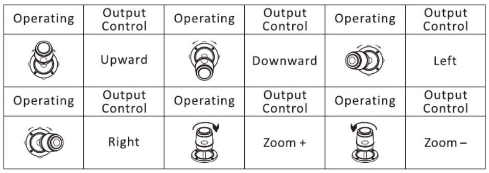
Press the joystick button to confirm in menu mode.
CONTROLLER SETUP (CNTRLR SETUP)
| Controller Setting | Description | |
| 1. Add Network (IP) Camera | Camera | Serial number of the camera, input 1-7, press [ENTER] to save. |
| Protocol | Options: VISCA (UDP), SONY VISCA (UDP),
VISCA (TDP), ONVIF. Select the protocol corresponding to camera. |
|
| IP Address | Camera IP address. | |
| Port | Input camera port number. | |
| Username/Password | Input username and password corresponding to each camera. | |
| 2. Add Analog Camera | Camera | Serial number of the camera, input 1-7, press [ENTER] to save. |
| Protocol | Select the protocol corresponding to camera. | |
| Address Code | Select the address code corresponding to camera. | |
| Baud Rate | Select the baud rate corresponding to camera. | |
| 3. Camera List | List of added cameras. Press button on top of joystick or press [ENTER] to confirm control. | |
| 4. Network Properties: Static/Dynamic | Network Properties | Switch via joystick left/right, press [ENTER] to confirm. |
| Dynamic | Dynamic allocation based on settings | |
| Static | Enter IP, gateway, subnet mask (make sure controller is assigned the same network segment as camera(s)) | |
| 5. Language EN/CN | Select English or Chinese (use joystick left/right). Press [ENTER] to confirm. | |
| 6. Sound | Turn key-press sound (‘beep’) ON/OFF (use joystick left/right). Press
[ENTER] to confirm selection. |
|
| 7. Reset | Restore controller to default settings. Double-click [ENTER] to confirm reset. Press [ESC] to cancel. | |
| 8. Controller Information | Check controller software version, hardware version, web version, gateway and subnet mask information. |
ADD NETWORK / IP CAMERA
To add a LAN / IP / Network Camera:
- Click [SETUP] to enter the Keyboard Settings and select Add Network Device.Keyboard Settings
- Add Network Device
- Add Analog Device
- Device List
- Network Attribute: Static
- Language: English
- Button Tone: Off
- Restore Factory
- System Info
- Input the camera IP address, protocol and port number. Press [ENTER] to confirm.
- Enter Device List and select the device you want to add using the joystick (up/down). Press the joystick button or press [ENTER] to control the selected device.
ADD ANALOG CAMERA
- Long press the joystick button to switch to analog model.
- Click [SETUP] to enter the Keyboard Settings and select Add Analog Device.
- Input the camera number (1-7), select the camera protocol, address code and baud rate, and press [ENTER] to confirm.
INQUIRY & CONTROL
- Click [SETUP] to enter the Keyboard Settings and select Device List to view the added devices.Keyboard Settings
- Add Network Device
- Add Analog Device
- Device List
- Network Attribute: Static
- Language: English
- Button Tone: Off
- Restore Factory
- System Info
- Use the joystick button to select the camera you want to control.
- When the screen shows the connection is successful, you can control the camera’s ptz, zoom, preset settings, etc.
USING THE WEB INTERFACE
Connect the joystick controller and a computer to the same LAN. Power on the joystick controller. When the joystick controller startup is complete, it will display its Native IP address on the screen Enter this IP in a browser to access the page configuration.

Enter the default login information:User Name: “admin”Password: “” (leave blank)
DEVICE MANAGEMENT
The Device Management interface will display as follows: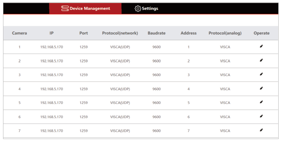
Click “button ” to add or modify parameters for a specific device.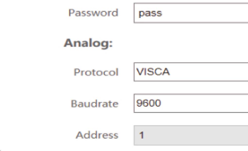
Input the camera number, corresponding IP address, port number and user name and click ‘Save’.
SETTINGS
NETWORKUse the Network function to modify the controller’s Network Type/IP acquisition method (dynamic or static) and port parameters as shown below:
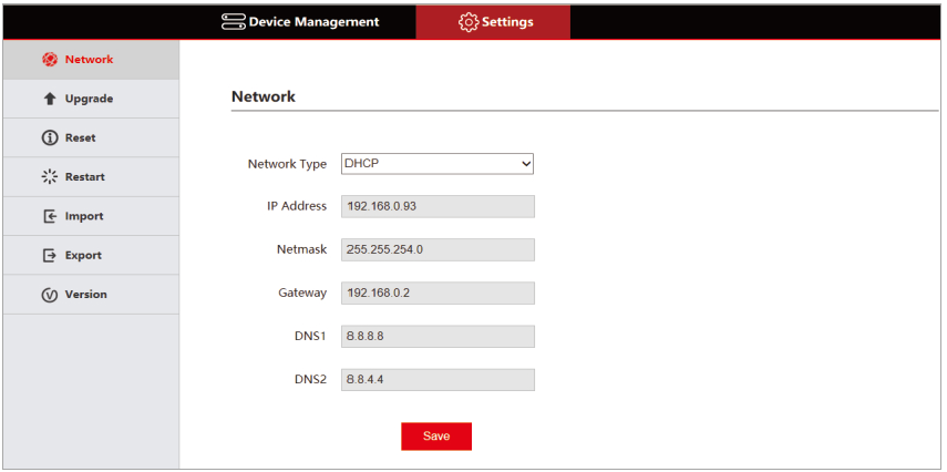
Dynamic Address (DHCP): DHCP is the default Network Type or acquisition method. The controller will request an IP address from the router automatically. When the request is successful, the IP address will appear on the controller’s display in the format: “Local IP: 192.168.x.xxx”Static Address (STATIC): When the user wants to set the network details, select STATIC as the Network Type and enter the required information.
UPGRADEThe Upgrade function is used to update the controller’s firmware. Select the firmware update file and click ‘Upgrade’. The controller will automatically restart after the upgrade is completed.Note: Do not operate the controller during the upgrade process. Do not power off the controller. Do not disconnect the controller from the network.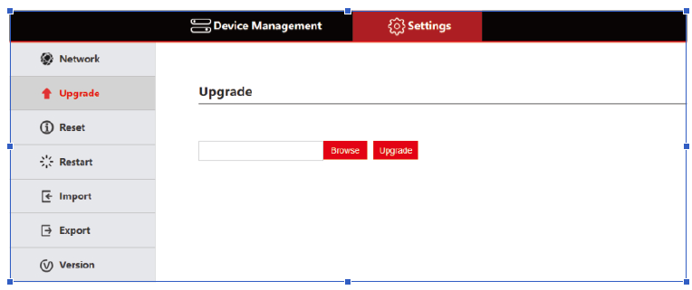
RESETUse the Reset function to remove all saved data/settings from the controller and return the controller to a static IP address. Use the Reset function with caution.
RESTARTPeriodically, the controller should be restarted for maintenance.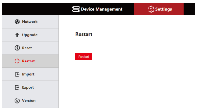
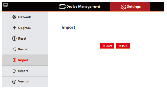
EXPORTUse the Export function to export device information to be imported by a different controller.
VERSIONUse the Version function to display the controller’s current firmware and hardware information.
Go Electronicwww.goelectronic.comPO Box 1864Lake Oswego, OR 97035 [email protected]
![]()
References
[xyz-ips snippet=”download-snippet”]