
![]() FM-300H andFM-300HRElectronic Disc Meter Owner’s Manual
FM-300H andFM-300HRElectronic Disc Meter Owner’s Manual
To the owner…Congratulations on receiving your GPI Electronic Disc Meter. We are pleased to provide you with a meter designed to give you maximum reliability and efficiency.Our business is the design manufacture, and marketing of liquid handling, agri- cultural, and recreational products. We succeed because we provide customers with innovative, reliable, safe, timely, and competitively-priced products. We pride ourselves on conducting our business with integrity and professionalism.We are proud to provide you with a quality product and the support you need to obtain years of safe, dependable service.
![]() PresidentGreat Plains Industries, Inc.
PresidentGreat Plains Industries, Inc.
GENERAL INFORMATION
This manual assists you in operating and maintaining your meter. Please take a few moments to acquaint yourself with the information here.If you need assistance, contact the dealer from whom you purchased your meter.If You Measure in LitresThis manual commonly refers to “gallons.” If your meter is factory calibrated in liters, consider all references to “gallons” apply equally to “liters.”![]() This symbol is used throughout the manual to call your attention to safety messages.
This symbol is used throughout the manual to call your attention to safety messages.![]() WARNINGWarnings alert you to the potential for personal injury.
WARNINGWarnings alert you to the potential for personal injury.![]() CAUTIONCautions call your attention to practices or procedures which may cause damage to your equipmentNotes give you information that can improve the efficiency of operations.It is your responsibility to:
CAUTIONCautions call your attention to practices or procedures which may cause damage to your equipmentNotes give you information that can improve the efficiency of operations.It is your responsibility to:
- make sure all operators have access to adequate instructions about safely operating and maintenance procedures.
- know and follow all safety precautions as specified by your chemical manufacturer for the handling of the fluid being metered.
Read Me!For your safety, review the major warnings and cautions below before operating your meter.
- This meter is approved to handle water, pesticides, fertilizers, and most industrial fluids. Do not use gasoline, diesel, or other fluids. Do not use this meter with flammable liquids.
- When handling hazardous chemicals, always follow the chemical manufacturer’s safety precautions. Wear protective clothing such as goggles, gloves, and respirators, as instructed.
- To avoid damage, DO NOT blow compressed air through the meter.
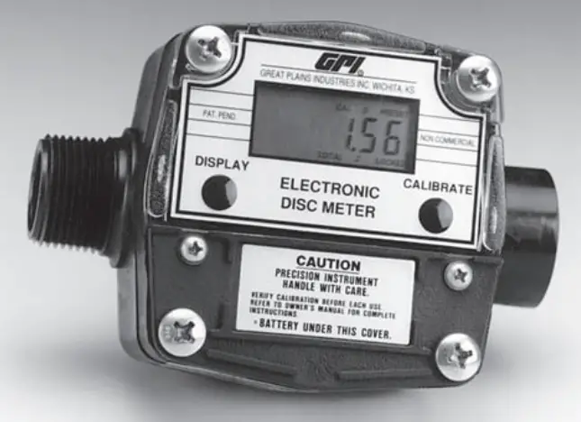
Your electronic disc meter is designed for measuring a wide range of chemicals. The meter translates flow data from the nutator disc into calibrated units shown on the meter’s readout. A field-replaceable battery provides power
BEFORE INSTALLATION
Upon receipt, examine your meter for visible damage. Remove protective plugs and caps for a thorough inspection. If any items are damaged or missing, contact your distributor.![]() CAUTIONTo avoid damage, DO NOT blow compressed air through the meter.If the meter is located in a rigid piping system where the fluid is trapped (for example, by gravity, valves, or nozzles) thermal expansion of the fluid can create pressure spikes that can damage a meter. Install a thermal relief valve or otherwise allow for thermal expansion of the fluid.Connect BatteryTo save power, this meter is shipped with the battery disconnected. Before using, connect the battery using the instructions below:
CAUTIONTo avoid damage, DO NOT blow compressed air through the meter.If the meter is located in a rigid piping system where the fluid is trapped (for example, by gravity, valves, or nozzles) thermal expansion of the fluid can create pressure spikes that can damage a meter. Install a thermal relief valve or otherwise allow for thermal expansion of the fluid.Connect BatteryTo save power, this meter is shipped with the battery disconnected. Before using, connect the battery using the instructions below:
- Remove the two large and two small screws from the battery cover plate located on the lower portion of the meter face.
- Remove the battery and plug into battery connections. When connected properly, numbers appear in the meter readout.
- Replace the gasket and battery cover and tighten securely. Torque the screws to 9 to 10 in. lbs.
INSTALLATION
NOTE: To avoid damage to the inlet and outlet, install this meter ONLY on plastic hose end or pipe fittings.
- To protect against leakage, seal all threads with two or three turns of Teflon® tape or a pipe thread sealant compatible with the liquid being measured. Make sure the Teflon® tape or sealant does not interfere with the flow.
- Hand-tighten the meter onto the fittings until snug. (Figure 1)

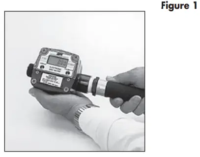
![]() CAUTIONTo avoid damage to the housing, DO NOT use a wrench.
CAUTIONTo avoid damage to the housing, DO NOT use a wrench.
BEFORE EACH USE
If the meter has been used before, make sure it is flushed and cleaned as outlined in the Maintenance Section.Press and release the DISPLAY button to ensure the meter is operating. Numbers will display from the last use.If the display becomes dim, faded or the low battery message appears (see below), the battery needs to be replaced. Reference the Maintenance Section for details. Also, check attery terminals for corrosion. To prevent corrosion from condensation, coat the terminals with petroleum jelly.

Verify Meter AccuracyBefore using, verify calibration and check the meter’s accuracy.
- If desired, hold down DISPLAY for three seconds to zero the meter’s Batch Total. When zeros appear, release the button.
- Meter an exact known volume into an accurate container. For best re- results, meter with one continuous full stream.
- Check the readout. If the amount metered is accurate, field calibration is not needed. If not, refer to the Calibration Section for further instructions.
NOTE: Best performance can be ob- trained by using the factory calibration.
OPERATION
![]() WARNINGThis meter is approved to handle water, pesticides, fertilizers, and most industrial fluids. Do not use gasoline, diesel, or other fuels.Do not use this meter with flammable liquids.Computer DisplayAll operations are reflected in the LCD readout. The large center digits indicate amounts, where smaller words or “icons” located above and below indicate specific information regarding totals, flow, calibration, and units of measure.Activate the MeterThe computer is on continuously and always ready to perform. The computer is powered by a field-replaceable battery. When the display becomes dim, faded or the low battery message appears, the battery needs to be replaced. Reference the Maintenance Section for details.Batch and Cumulative TotalsThe computer maintains two totals. The Cumulative Total provides continuous measurement and cannot be manually reset. The Batch Total can be reset to measure flow during a single-use. The Cumulative Total is labeled TOTAL 1, Batch Total is labeled TOTAL 2 BATCH.When the Cumulative Total reaches a display reading of 999,999 the computer will highlight an X10 icon. This indicates to the operator that zero must be added to the 6 digits shown. When the next rollover occurs, the computer will highlight an X100 icon. This indicates to the operator that two zeros must be added to the 6 digits shown.Press the DISPLAY button briefly to switch between the TOTAL 1, TOTAL 2 BATCH, and FLOWRATE (if applicable). Press DISPLAY briefly to display the TOTAL 2BATCH. Hold the DISPLAY button for 3 seconds to reset the Batch Total to zero. When fluid is flowing through the meter, a small propeller icon is highlighted.Flowrate FeatureSome models have of Rate of Flow mode. To use this feature, press and release DISPLAY until the FLOWRATE icon appears. The factory-set time base will be highlighted to the right of FLOWRATE (M = minutes). When FLOWRATE is invoked, the display will be indicating the rate of flow.
WARNINGThis meter is approved to handle water, pesticides, fertilizers, and most industrial fluids. Do not use gasoline, diesel, or other fuels.Do not use this meter with flammable liquids.Computer DisplayAll operations are reflected in the LCD readout. The large center digits indicate amounts, where smaller words or “icons” located above and below indicate specific information regarding totals, flow, calibration, and units of measure.Activate the MeterThe computer is on continuously and always ready to perform. The computer is powered by a field-replaceable battery. When the display becomes dim, faded or the low battery message appears, the battery needs to be replaced. Reference the Maintenance Section for details.Batch and Cumulative TotalsThe computer maintains two totals. The Cumulative Total provides continuous measurement and cannot be manually reset. The Batch Total can be reset to measure flow during a single-use. The Cumulative Total is labeled TOTAL 1, Batch Total is labeled TOTAL 2 BATCH.When the Cumulative Total reaches a display reading of 999,999 the computer will highlight an X10 icon. This indicates to the operator that zero must be added to the 6 digits shown. When the next rollover occurs, the computer will highlight an X100 icon. This indicates to the operator that two zeros must be added to the 6 digits shown.Press the DISPLAY button briefly to switch between the TOTAL 1, TOTAL 2 BATCH, and FLOWRATE (if applicable). Press DISPLAY briefly to display the TOTAL 2BATCH. Hold the DISPLAY button for 3 seconds to reset the Batch Total to zero. When fluid is flowing through the meter, a small propeller icon is highlighted.Flowrate FeatureSome models have of Rate of Flow mode. To use this feature, press and release DISPLAY until the FLOWRATE icon appears. The factory-set time base will be highlighted to the right of FLOWRATE (M = minutes). When FLOWRATE is invoked, the display will be indicating the rate of flow.
CALIBRATION
Factory and Field CalibrationAll calibration information is visible to the user as icons on the top line of the display, above the numeric digits.All units are configured with a “factory” calibration. Some models are calibrated with gallons (GL) and others calibrated with liters (LT). This factory calibration (indicated with FAC) is permanently programmed into the computer and is not user-adjustable.The “field” calibration may be set by the user and can be changed or modified at any time using the calibration procedure described in the Calibration section. Totals or flowrate derived from the field calibration are invoked when the FAC icon is no longer visible on the top line of the display.Field CalibrationFactory calibration settings are custom-programmed into each flowmeter during production and are correct for light fluids such as water or heavier liquids like pesticides or light oil. However, readings using the standard factory calibration curves may not be accurate in some situations – variations in chemical formulation, viscosity, temperature, and flow rates all affect meter accuracy. To ensure accuracy, it is important to check accuracy frequently and field calibrate when necessary.Field Calibration Procedures (Dispense/Display Method)
- To field calibrate, press and hold the CALIBRATE and DISPLAY buttons for about 3 seconds until you see FLdCAL. Release both buttons and you will see dd000.0. You are now in the field calibration mode.
- Dispense a known amount of fluid at a flowrate representative of the application. Any amount between .1 and 999.9 units can be used. The display will count up while fluid is flowing through the meter.
- The DISPLAY button can then be pushed to select the digit location and the CALIBRATE button can be pushed to scroll the desired value at the blinking position. Edit the amount shown with the value that was dis- pensed above. Values from 000.1 to 999.9 can be entered.
- When satisfied with the value, press both CALIBRATE and DISPLAY buttons simultaneously. the calendar will be displayed and the unit will go back to normal operation, less the FAC (factory calibration) icon.
- The meter will now be operating with a custom calibration number unique to the above dispense procedure. No unit of measure (gallon, liter, etc.) icon will be highlighted.
NOTE: If the field calibration mode is entered and NO fluid is dispensed, then upon leaving, the computer will use data from the last successful field calibration.Calibration ContainerThe desired calibration container should be uniformly dependable and constructed with a graduated neck. The container’s volume indicator should be clearly and precisely marked. It is helpful if the container’s material allows a window through which the level of liquid can be viewed. GPI offers a properly designed calibration container for volumes of 5 gallons or 5 liters.DO NOT use several smaller containers or a larger container with a 5-gallon marking.For the most accurate results, dispense at flowrates that best simulate your actual operating conditions. Avoid “dribbling” more fluid or repeatedly starting and stop- ping the flow. These actions will result in less accurate calibrations.During calibration, make sure you meet the meter’s minimum flowrate requirements of 2 GPM (7 LPM).Before calibrating, purge the system of air using instructions in the Before Each Use section.
MAINTENANCE
This meter is virtually maintenance-free.It is important, however, that the nutator disc moves freely.To prevent the drying of chemicals on internal assemblies, meters should be kept free of chemicals when not in use for extended periods of time. Flush and clean after each use to promote trouble-free operation.Removal![]() WARNINGDuring meter removal, chemicals may spill. Follow the chemical manufacturer’s safety precautions for cleanup of minor spills.
WARNINGDuring meter removal, chemicals may spill. Follow the chemical manufacturer’s safety precautions for cleanup of minor spills.
- Ensure all chemical is drained from the meter. This could include draining the hose, meter, and nozzle.
- Wearing protective clothing, loosen the meter from fittings by hand.
![]() CAUTIONTo avoid damage to the housing, do not use a wrench.If the meter is not immediately installed again, cap the hose end to prevent spills and drying. The nozzle could be used for this purpose. Flush the meter if it will not be in use for more than two weeks.FlushingWhen removed or not in use for more than two weeks, flush the meter to remove chemical residue.
CAUTIONTo avoid damage to the housing, do not use a wrench.If the meter is not immediately installed again, cap the hose end to prevent spills and drying. The nozzle could be used for this purpose. Flush the meter if it will not be in use for more than two weeks.FlushingWhen removed or not in use for more than two weeks, flush the meter to remove chemical residue.![]() CAUTIONDo not submerge the meter.If needed, clean the meter using Cleaning instructions.CleaningDuring use, the meter should be kept free of liquid to ensure drying does not occur inside the meter. If drying should occur, the nutator will stick or drag, affecting accuracy.If this occurs, cleaning is required.Cleaning the Nutator
CAUTIONDo not submerge the meter.If needed, clean the meter using Cleaning instructions.CleaningDuring use, the meter should be kept free of liquid to ensure drying does not occur inside the meter. If drying should occur, the nutator will stick or drag, affecting accuracy.If this occurs, cleaning is required.Cleaning the Nutator
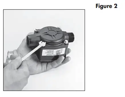
- Loosen the screws on the back of the meter about 1/4 inch (0.6 cm). (Figure 2)
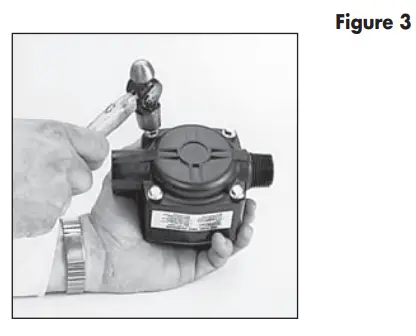
- Tap the screws with a hammer to loosen the cover plate from the housing. (Figure 3) Remove the screws and washers.
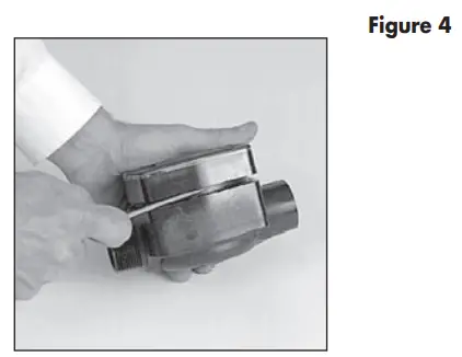
- Gently pry the cover plate from the housing. Take care not to damage the cover plate, housing, or O-ring. (Figure 4)
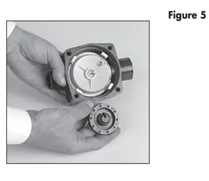
- Remove the signal generator from the pin on the nutator disc. (Figure 5
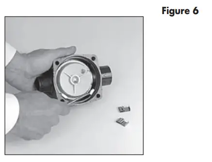
- Gently remove the metal clips holding the nutator in place. (Figure 6) Take care not to damage the O-ring on the nutator inlet.
- Remove the nutator.
- Using water or a solvent-based fluid and a brush, carefully remove residue from the nutator disc, nutator halves, signal generator, and inside of the housing. Allow all parts to dry.CAUTIONDo not submerge the meter.
- When the nutator turns freely, assemble and install following the instructions below.
Assemble Nutator
- Assemble the nutator disc and nuta-tor halves. Install the O-ring on the nutator inlet.
- Install the nutator in the meter housing. Make sure the nutator O-ring fits properly against the meter inlet.
- Secure the nutator with metal clips. Beginning opposite the inlet, install a clip in each slot in the housing. Push each clip down firmly until seated.
- Place the signal generator on the nu- tator pin. Make sure it rotates freely on the pin.
- Coat the O-ring lightly with bearing grease and seat securely on the coverplate.
- With the display facing up, turn the coverplate to the desired orientation. Align holes on the coverplate and housing.
- Secure the coverplate by evenly tightening screws to 25 to 35 in. lbs.
StorageAfter thoroughly cleaning the meter, disconnect the battery and store the meter in a clean, dry location.Battery ReplacementYour meter is equipped with a field-replaceable 9-volt alkaline battery.If the meter’s readout should become dim, blank, faded, or the low battery message appears, replace the battery.Batch and Cumulative Totals, as well as, Factory and Field Calibrations are not lost when the battery is replaced or power is lost. They are saved in the meter’s computer and are available after a new battery is installed. You do not need to repeat Field Calibration.Check the battery and terminals at least every year to ensure proper operation. It is strongly recommended that terminals be cleaned annually.NOTE: The battery can be replaced without removing the meter from the hose or pipe.To replace battery or clean terminals:
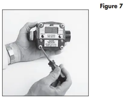
- Remove the two large and two small screws from the battery coverplate located on the lower portion of the meter face. (Figure 7)
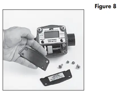
- Remove the battery coverplate and gasket. (Figure 8)
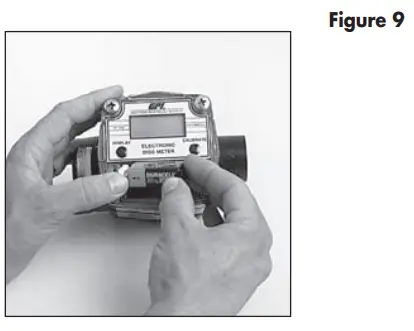
- Remove the battery and, if necessary, clean corrosion from the battery terminals. (Figure 9) To prevent corrosion from condensation, coat the terminals with petroleum jelly.
- Install the new battery.When the battery is installed correctly, the computer powers on automatically. Check the readout to make sure normal meter functions have resumed before assembling again. If necessary, seat the battery again.
- Make sure the coverplate gasket is in good condition and properly seated. Replace, if needed.
- Replace the battery cover. Torque the screws to 9 to 10 in. lbs.
End of SeasonTo ensure proper operation, the meter should be cleaned prior to extended periods of inactivity and at the end of the season before storage. Disconnect the battery before storage.
TROUBLESHOOTING
|
SYMPTOM |
PROBABLE CAUSE |
CORRECTIVE ACTION |
| A. METER IS NOT ACCURATE | 1. Field Calibration not performed properly2. Factory Calibration not suitable for the liquid being measured3. Meter operated below minimum flowrate4. Meter partially clogged with dried liquid5. Teflon® tape or another material inflow path6. Nutator misaligned | Field calibrate again or select Factory Calibration.Perform a Field Calibration according to Calibration Section.Increase flowrate. See Specifications Section.Remove meter. Disassemble and carefully clean dried chemicals from the nutator. Make sure the nutating disc moves freely. Assemble again.Remove meter. Clear material from flow path and seal fittings. Install again.Disassemble the meter and install the nutator again. Ensure O-ring and retainer clips are in place. |
| B. READOUT FADED OR BLANK | 1. Batteries weak, dead, or not connected2. Battery terminal corroded3. Computer defective | Replace battery. Install again, making sure the gasket seats evenly around the coverplate.Clean corrosion from the terminals.Contact the factory. |
| C. NORMAL FLOW RATE BUT METER DOES NOT COUNT (Meter comes on when DISPLAY button pushed.) | 1. Field Calibration not performed correctly2. Nutator misaligned3. Signal generator disc missing or damaged4. Computer defective | Field calibrate again or select Factory Calibration.Disassemble the meter and install the nutator again. Ensure O-ring and retainer clips are in place.Replace the signal generator disc. Contact the factory.Contact the factory. |
| D. REDUCED FLOW- RATE & METER DOES NOT COUNT (Meter comes on when DISPLAY button pushed.) | 1. Meter clogged with dried liquids | Remove meter. Disassemble and clean dried chemicals from the nutator. Make sure the nutating disc moves freely.Assemble again. |
| E. CANNOT GET METER INTO FIELD CALIBRATION | 1. Button push sequence incorrect2. Computer circuit board defective | Make sure CALIBRATE is held down while DISPLAY is pushed. Hold both buttons for 3 seconds. The readout will then show dd-000.0. Release both buttons.Proceed with calibration according to Calibration Section.Contact the factory. |
| F. METER CONNECTIONS LEAK | 1. Meter installed without thread sealant2. Connecting threads damaged3. Screws on back of meter lose4. Coverplate O-ring missing, damaged or improperly installed5. Meter housing cracked | Remove meter. Wrap male connections with 3 to 4 wraps of thread tape or compatible sealing compound. Install again.Remove meter and inspect threads. Replace damaged connections. If threads are damaged, contact the factory.Tighten screws. Torque to 25 to 35 in.lbs.Install O-ring on coverplate again.Inspect housing for cracks. If cracks are present, contact the factory. |
ILLUSTRATED PARTS LIST
 |
 |
|
Item No. |
Part No. |
Description Req’d. No. |
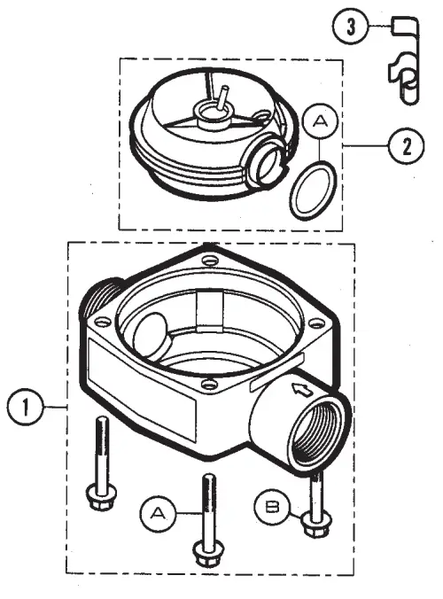
| 1 | 120505-1 | Housing Kit…………………….. 1 |
| 1-A | 904004-19 | Screw, 1/4-20 x 1-3/4 in…… 4 |
| 1-B | 904005-29 | Washer, 1/4 in…………………. 4 |
| 2 | 120503-1 | Nutator Kit ……………………… 1 |
| 2-A | 111045-4 | Nutator Seal …………………… 1 |
| 3 | 120013-1 | Clip ……………………………….. 4 |
| 4 | 120504-1 | Signal Generator Kit ………… 1 |
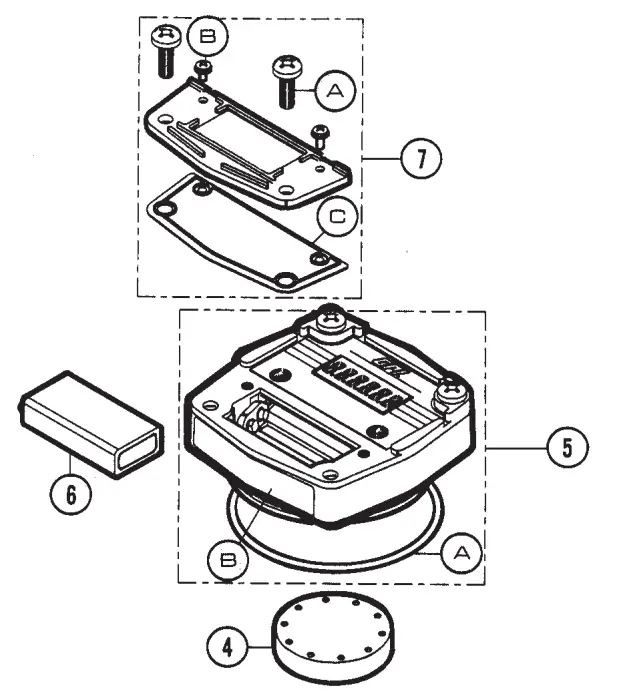
| 5* | 120502-11 | Coverplate Assy Kit, gallon . 1 |
| 120502-18 | Coverplate Assay Kit, liter….. 1 | |
| 5-A | 901001-78 | O-ring ……………………………. 1 |
| 6 | 902004-20 | 9 Volt Transistor Battery …… 1 |
| 7* | 120501-3 | Battery Cover and Gasket Kit………………………. 1 |
| 7-A | 904005-28 | Self-Sealing Screw, 1/4-20 x 5/8 in. ……………….. 2 |
| 7-B | 904005-27 | Seems Screw, 6-32 x 3/8 in. ………………….. 2 |
| 7-C | 120028-1 | Gasket …………………………… 1 |
* The Battery Cover and Gasket Kit, Item 7, is included in the Coverplate Assembly Kit, Item 5.
SPECIFICATIONS
 report this ad
ApplicationsFlow Range: 2-20 GPM (7-75 LPM) Operating Environment: Outdoor, operating temperature range of 0° F to +130° F (-18° C to +54° C).Electronic Nutating Disc designed for mounting on hoses or pumps of fluid transfer systems.Power: 9 Volt alkaline batteryMaximum Working Pressure: 50 PSIG (3.4 bar)Maximum Display Value: 999,999 (x100)AccuracyFactory Calibration: ± 2%Field Calibration: ± 0.5%MaterialsHousing: PBT PolyesterSeals: VitonWetted Parts: PBT Polyester, 303/304Stainless Steel, FerriteMechanicalInlet: 1-inch NPT femaleOutlet: 1-inch NPT maleDimensionsHeight: 4 inches (10.3 cm)Depth: 3.1 inches (8.1 cm)Width: 6 inches (15.2 cm)Shipping Weight3 lbs. (1.4 kg)Storage Temperature-40° F to +158° F (-40° C to +70° C)
SERVICE
For warranty consideration, parts, or other servicing information, please contact your local distributor. If you need further assistance, call the GPI Customer Service Department in Wichita, Kansas, during normal business hours.1-800-835-0113To obtain prompt, efficient service, always be prepared with the following information:
- The model number of your meter.
- The serial number or manufacturing date code of your meter.
- Specific information about part numbers and descriptions.
For warranty work always be prepared with your original sales slip or other evidence of purchase date.Returning PartsPlease contact the factory before re-turning any parts. It may be possible to diagnose the trouble and identify needed parts in a telephone call or letter. GPI can also inform you of any special handling requirements you will need to follow covering the transportation and handling of equipment that has been used to transfer hazardous liquids.![]() CAUTIONDo not return meters without specific authority from the GPI Customer Service Department. Due to strict regulations governing transportation, handling, and disposal of hazardous liquids, GPI will not accept meters for rework unless they are completely free of chemicals.Limited Warranty PolicyGreat Plains Industries, Inc. 5252 E. 36th Street North, Wichita, KS USA 67220-3205, hereby provides a limited warranty against defects in material and workmanship on all products manufactured by Great Plains Industries, Inc. This product includes a 2-year warranty from the date of purchase as evidenced by the original sales receipt. A 30-month warranty from the product date of manufacture will apply in cases where the original sales receipt is not available. Reference product labeling for the warranty expiration date based on 30 months from the date of manufacture. Manufacturer’s sole obligation under the foregoing warranties will be limited to either, at Manufacturer’s option, replacing or repairing defective Goods (subject to limitations hereinafter provided) or refunding the purchase price for such Goods theretofore paid by the Buyer, and Buyer’s exclusive remedy for breach of any such war- rates will be enforcement of such obligations of Manufacturer. The warranty shall extend to the purchaser of this product and to any person to whom such product is transferred during the warranty period.This warranty shall not apply if:A. the product has been altered or modified outside the warrantor’s duly appointed representative;B. the product has been subjected to neglect, misuse, abuse, or damage or has been installed or operated other than in accordance with the manufacturer’s operating instructions.To make a claim against this warranty, contact the GPI Customer Service Department at 316-686-7361 or 800-835-0113. Or by mail at:Great Plains Industries, Inc.5252 E. 36th St. NorthWichita, KS, USA 67220-3205GPI will step you through a product troubleshooting process to determine appropriate corrective actions.GREAT PLAINS INDUSTRIES, INC., EXCLUDES LIABILITY UNDER THIS WARRANTY FOR DIRECT, INDIRECT, INCIDENTAL, AND CONSEQUENTIAL DAMAGES INCURRED IN THE USE OR LOSS OF USE OF THE PRODUCT WARRANTED HEREUNDER.The company herewith expressly disclaims any warranty of merchantability or fitness for any particular purpose other than for which it was designed.This warranty gives you specific rights and you may also have other rights which vary from U.S. state to U.S. state.Note: In compliance with MAGNUSON MOSS CONSUMER WARRANTY ACT – Part 702 (governs the resale availability of the warranty terms).
CAUTIONDo not return meters without specific authority from the GPI Customer Service Department. Due to strict regulations governing transportation, handling, and disposal of hazardous liquids, GPI will not accept meters for rework unless they are completely free of chemicals.Limited Warranty PolicyGreat Plains Industries, Inc. 5252 E. 36th Street North, Wichita, KS USA 67220-3205, hereby provides a limited warranty against defects in material and workmanship on all products manufactured by Great Plains Industries, Inc. This product includes a 2-year warranty from the date of purchase as evidenced by the original sales receipt. A 30-month warranty from the product date of manufacture will apply in cases where the original sales receipt is not available. Reference product labeling for the warranty expiration date based on 30 months from the date of manufacture. Manufacturer’s sole obligation under the foregoing warranties will be limited to either, at Manufacturer’s option, replacing or repairing defective Goods (subject to limitations hereinafter provided) or refunding the purchase price for such Goods theretofore paid by the Buyer, and Buyer’s exclusive remedy for breach of any such war- rates will be enforcement of such obligations of Manufacturer. The warranty shall extend to the purchaser of this product and to any person to whom such product is transferred during the warranty period.This warranty shall not apply if:A. the product has been altered or modified outside the warrantor’s duly appointed representative;B. the product has been subjected to neglect, misuse, abuse, or damage or has been installed or operated other than in accordance with the manufacturer’s operating instructions.To make a claim against this warranty, contact the GPI Customer Service Department at 316-686-7361 or 800-835-0113. Or by mail at:Great Plains Industries, Inc.5252 E. 36th St. NorthWichita, KS, USA 67220-3205GPI will step you through a product troubleshooting process to determine appropriate corrective actions.GREAT PLAINS INDUSTRIES, INC., EXCLUDES LIABILITY UNDER THIS WARRANTY FOR DIRECT, INDIRECT, INCIDENTAL, AND CONSEQUENTIAL DAMAGES INCURRED IN THE USE OR LOSS OF USE OF THE PRODUCT WARRANTED HEREUNDER.The company herewith expressly disclaims any warranty of merchantability or fitness for any particular purpose other than for which it was designed.This warranty gives you specific rights and you may also have other rights which vary from U.S. state to U.S. state.Note: In compliance with MAGNUSON MOSS CONSUMER WARRANTY ACT – Part 702 (governs the resale availability of the warranty terms).
![]() GREAT PLAINS INDUSTRIES, INC.5252 East 36th Street NorthWichita, KS USA 67220-3205TEL: 316-686-7361FAX: 316-686-6746“A Great Plains Ventures Subsidiary”www.gpipumps.net1-800-835-0113GPI is a registered trademark of Great Plains Industries, Inc.© 2010 by GREAT PLAINS INDUSTRIES, INC., Wichita, KS.Printed in the U.S.A. 06/10Rev. C 920679-06
GREAT PLAINS INDUSTRIES, INC.5252 East 36th Street NorthWichita, KS USA 67220-3205TEL: 316-686-7361FAX: 316-686-6746“A Great Plains Ventures Subsidiary”www.gpipumps.net1-800-835-0113GPI is a registered trademark of Great Plains Industries, Inc.© 2010 by GREAT PLAINS INDUSTRIES, INC., Wichita, KS.Printed in the U.S.A. 06/10Rev. C 920679-06
[xyz-ips snippet=”download-snippet”]