G8 Portable Fuel Transfer Pump
GENERAL INFORMATION
This pump is designed for use only with gasoline (up to 15% alcohol blends such as E15), diesel fuel (up to 20% biodiesel blends such as B20) and kerosene. Do not use this pump for dispensing any fluids other than those for which it was designed. To do so may damage pump components and will void the warranty.This pump is designed to operate on a typical 12-volt DC automotive electrical system. The pump is designed to operate with 12-volts DC at the motor leads and the ratings are determined at this voltage. Performance may vary due to length of power cord, battery condition or output from vehicle charging system that will affect system voltage.NOTE: This pump is not intended for use with an automatic nozzle.
WARNING: This product shall not be used for pumping fuel or other liquids into aircraft.
NOTE: An automatic bypass valve prevents pressure build up when the pump is on with the nozzle closed. To avoid motor damage, do not run the pump more than 5 minutes with the nozzle closed.
The rated duty cycle of this pump is 15 minutes ON and 30 minutes OFF. Allow the pump to cool for 30 minutes.Do not leave the system running without fluids. “Dry running” can damage the pump. If the system fails to deliver fuel after 15 to 20 seconds, turn the system off and refer to the Troubleshooting Section.Do not pump the tank completely dry, as contaminants from the bottom of the tank may enter the pump. IMPORTANT! DO NOT RETURN THIS PRODUCT TO THE STORE. Please contact Great Plains Industries, Inc. before returning any product. If you are missing parts, or experience problems with your installation, contact our Customer Support Department. We will be happy to assist you. Call 800-835-0113 or 316-686-7361 oremail: [email protected].
SAFETY INFORMATION
Observe all safety precautions concerning safe handling of petroleum fuels.For your safety, please take a moment to review the warnings throughout this manual.To prevent physical injury, observe precautions against fire or explosion when dispensing fuel. Do not operate the system in the presence of any source of ignition including running or hot engines, lighted cigarettes, or gas or electric heaters.Observe precautions against electrical shock when operatingthe system. Serious or fatal shock can result from operating electrical equipment in damp or wet locations.Inspect external pump wiring regularly to make sure it is in good condition. To avoid electrical shock, use extra care when connecting the pump to power.Avoid prolonged skin contact with petroleum fuels. Use protectivegoggles, gloves, and aprons in case of splashing or spills. Changesaturated clothing and wash skin promptly with soap and water.Observe precautions against electrical shock when servicing the pump. Always disconnect power before repairing or servicing.Never apply electrical power to the system when any of the coverplates are removed.If using solvent to clean pump components or tank, observe the solvent manufacturer’s recommendations for safe use and disposal.
INSTALLATION & OPERATION
Pump Installation
Make sure all threaded fuel connections are wrapped with three to four turns of the supplied thread tape.Make sure supply tank or container is vented. A vent cap rated at 3 psi or less is recommended.NOTE: These components have not been evaluated as part of the UL Listed Equipment and are not intended for use in a Hazardous (Classified) Location.
Install Inlet Hose and Strainer
Wrap the threads of one end of the inlet hose 3 or 4 times with thread tape (supplied). Install hose end into inlet side of pump (see Figure 1) and tighten. Wrap threads on other end of hose 3 or 4 times with thread tape (supplied). Install metal strainer and tighten. To avoid damage to pump from dirt and debris, do not operate pump without strainer.
Install Outlet Hose and Nozzle
Wrap the threads of one end of the outlet hose 3 or 4 times with thread tape (supplied). Install hose into outlet side of pump (see Figure 1) and tighten. Wrap threads on other end of hose 3 or 4 times with thread tape (supplied). Install manual nozzle and tighten. To minimize static electricity build up and possible explosion, use only static wire conductive hose when pumping
flammable fluids. Keep the fill nozzle in constant contact with the container being filled during the filling process. Sparks or static discharge will cause explosions.
Install Ground Wire
An external ground wire is provided for use where required. GPI strongly recommends grounding your pump prior to use. To attach the ground wire, remove one of the 1/4-20 x 1/2” hex head screws and install the ground wire ring terminal (see Figure 2). Reinstall hex head screw and tighten securely. Attach the alligator clamp end of the ground wire to the earth or chassis ground of the vehicle your are filling.
Connect to Power Source
NOTE: This pump is designed to operate on a typical 12-volt DC automotive electrical system.DO NOT attempt to connect to a 24- volt or 115-volt electrical system.WARNING: Carefully route the power cord to the battery, protecting the power cord from hot surfaces, sharp edges or anything that could damage the power cord, resulting in a short circuit.A 20-amp inline fuse is supplied on the power cord’s red wire to protect the motor and power cord. Connect the red wire with red clamp to the positive (ungrounded) side of the power source. Connect black wire with black clamp to the negative (grounded) side of the power source.NOTE: Power cord components, such as the switch and fuse, have not been evaluated as part of the U. L. Listed equipment.
NOTE: This pump is pre-wired for installation in CLASS I, DIVISION 2 locations such as portable fuel tanks, trailers, etc. Connection to a battery will depend upon the application.WARNING: This pump is not intended for use in CLASS I, DIVISION I locations.
Dispense Fuel
First, insert the nozzle into the receiving tank, and then turn on the pump with the inline switch (see Figure 3). Squeeze the nozzle handle to start fuel flow. When done, release the nozzle handle and turn the pump off at the switch. Always insert nozzle into tank before turning pump on.This pump is designed to be selfpriming. If fuel is not delivered within 15 to 20 seconds, turn the pump off and refer to the Troubleshooting Section of this manual.An automatic bypass valve prevents pressure build up when the pump is on with the nozzle closed. To avoid pump damage, do not run the pump more than 5 minutes with the nozzle closed.After running the pump for a maximum of 15 minutes, allow it to cool for 30 minutes.When finished refueling, make sure the pump is turned off at the switch and disconnect the power cord from the 12-volt power source.
MAINTENANCE
This pump is designed for minimum maintenance. Motor bearings are sealed and require no lubrication. Inspect the pump and components regularly for fuel leaks and make sure the hose and power cord are in good condition. Keep the pump exterior clean to help identify leaks.Do not use this pump for water, chemicals or herbicides. Dispensing any fluid other than that listed in this manual will damage the pump. Use of the pump with unauthorized fluids will void the warranty.A kit containing O-rings, motor shaft seal and gears is available for this pump. To order replacement kit, contact GPI and ask for part number #147500-01 Gears and SealsOverhaul Kit.
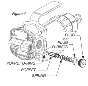
Inspect and Service Bypass Poppet
To clean and service the Bypass Poppet (see Figure 4):
- Remove the bypass plug with O-ring, Spring, and poppet with O-ring.
- Wipe parts and poppet cavity with a clean cloth.
- When inspecting O-rings, look for breaks, wear, and signs of deterioration, such as swelling.
- Replace O-rings as necessary.
- Before seating, coat O-rings with light grease.
- Make sure O-rings are well seated and reinstall bypass poppet assembly.
- Before installing the plug, unwrap thread 3 or 4 times with thread tape. Torque plug to 90 – 100 in•lbs.
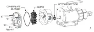
Inspect and Service Gears
To clean and service gears (See Figure 5):
- Remove the (4) 1/4-20 socket head screws, (2) hex nuts, handle and gear coverplate.
- Remove coverplate O-ring and inspect for wear or damage. Replace as needed.
- Before seating, coat O-rings with light grease.
- Remove the gears and inspect for wear or damage. Replace gears as needed, making sure they turn freely.
- Reinstall, coverplate, handle nuts and hex screws (longer screws are on top. Torque hex screws to 75 -85 in•lbs.
Inspect and Replace Motorshaft Seal
To inspect and replace shaft seal (See Figure 5):
- Remove the (4) 1/4-20 socket head screws, (2) hex nuts, handle and gear coverplate.
- Remove the pump housing. The motorshaft seal is located on the backside of the pump housing.
- Carefully remove shaft seal, (noting orientation) and inspect for wear or damage. Replace as needed, making sure seal is well seated in recess.
- Reinstall all parts. Torque hex screws to 75 -85 in•lbs.
TROUBLESHOOTING
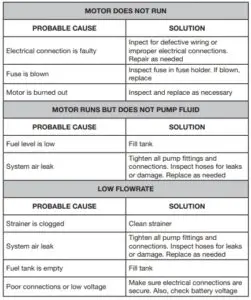
For further assistance, visit gpi.net/solutions-center or call 1-800-835-0113.
SPECIFICATIONS
APPLICATIONS
The G8 Fuel Transfer Pump is designed to safely transfer low viscosity petroleum fuels such as gasoline (up to 15% alcohol blends such as E15), diesel fuel (up to 20% biodiesel blends such as B20) and kerosene.
PUMP HOUSING
Corrosion-resistant aluminum.
PERFORMANCE
Pump Rate: Up to 8 GPM (30 LPM)Duty Cycle: 15 min. ON, 30 min. OFFSuction Lift: Up to 5.5 ft. (1.7 m)
OPERATING TEMPERATURE
-20°F to +125°F (-29°C to +52°C)
OPERATING PRESSURE
10 PSI / 0.69 bar
ELECTRICAL
Input: 12-volt DCCurrent Draw: 15 ampMotor: 1100 RPM, 1/10 HP, Listed to UL and Canadian Standards
MECHANICAL CONNECTIONS
Inlet: 3/4” NPTOutlet: 3/4” NPT
SHIPPING WEIGHT
15.4 lbs / (6.9 kg)
PARTS & SERVICE
In order to preserve the UL Listing for the motor, do not attempt to servicethe motor. For products serviced outside the factory, the UL nameplate must be defaced to indicate that the equipment may no longer meet the requirements for UL Listing. This does not apply to products serviced outside the factory under the UL program for Rebuilt Motors for Use in Hazardous Locations. For warranty consideration, parts, or other service information, please contact your local distributor. If you need further assistance, contact the GPI Customer Service Department in Wichita, Kansas, during normal business hours.A toll free number is provided for your convenience.1-800-835-0113To obtain prompt, efficient service, always be prepared with the following information:
- The model number of your pump.
- The serial number or manufacturing date code of your pump.
- Part descriptions and numbers. For warranty work, always be prepared with your original sales slip or other evidence of purchase date.
Please contact GPI before returning any parts. It may be possible to diagnose the trouble and identify needed parts in a telephone call. GPI can also inform you of any special requirements you will need to follow for shipping fuel dispensing equipment.
CAUTION: Do not return the pump or parts without prior approval from the GPI Customer Service Department. Due to strict government regulations, GPI cannot accept parts unless they have been drained and cleaned.
LIMITED WARRANTY
Great Plains Industries, Inc. 5252 E. 36th Street North, Wichita, KS USA 67220-3205, hereby provides a limited warranty against defects in material and workmanship on all products manufactured by Great Plains Industries, Inc. This product includes a 2 year warranty from date of purchase as evidenced by the original sales receipt. A 30 month warranty from product date of manufacture will apply in cases where the original sales receipt is not available. Reference product labeling for the warranty expiration date based on 30 months from date of manufacture. Manufacturer’s sole obligation under the foregoing warranties will be limited to either, at Manufacturer’s option, replacing or repairing defective Goods (subject to limitations hereinafter provided) or refunding the purchase price for such Goods theretofore paid by the Buyer, and Buyer’s exclusive remedy for breach of any such warranties will be enforcement of such obligations of Manufacturer. The warranty shall extend to the purchaser of this product and to any person to whom such product is transferred during the warranty period. This warranty shall not apply if:
A. the product has been altered or modified outside the warrantor’s duly appointed representative;B. the product has been subjected to neglect, misuse, abuse or damage or has been installed or operated other than in accordance with the manufacturer’s operating instructions.
To make a claim against this warranty, contact the GPI Customer Service Department at316-686-7361 or 800-835-0113. Or by mail at:Great Plains Industries, Inc.5252 E. 36th St. NorthWichita, KS, USA 67220-3205
The company will step you through a product troubleshooting process todetermine appropriate corrective actions. GREAT PLAINS INDUSTRIES, INC., EXCLUDES LIABILITY UNDER THIS WARRANTY FOR DIRECT, INDIRECT, INCIDENTAL AND CONSEQUENTIAL DAMAGES INCURRED IN THE USE OR LOSS OF USE OF THE PRODUCT WARRANTED HEREUNDER.The company herewith expressly disclaims any warranty of merchantability or fitness for any particular purpose other than for which it was designed. This warranty gives you specific rights and you may also have other rights which vary from U.S. state to U.S. state.Note: In compliance with MAGNUSON MOSS CONSUMER WARRANTY ACT – Part 702 (governs the resale availability of the warranty terms).
GPI G8 Portable Fuel Transfer Pump User Manual – GPI G8 Portable Fuel Transfer Pump User Manual –
[xyz-ips snippet=”download-snippet”]