![]() Outside Humidity / Temperature Transmitter
Outside Humidity / Temperature Transmitter
![]() HTOS Series – Installation Instructions
HTOS Series – Installation Instructions
INTRODUCTION
The outside humidity/temperature transmitter series uses a highly accurate and reliable Thermoset Polymer-based capacitance humidity sensor and Platinum RTD temperature sensor together with state-of-the-art digital linearization and temperature compensated circuitry to monitor humidity levels. A hinged, gasketed weatherproof Polycarbonate enclosure provides ease of installation and protection from the elements.
BEFORE INSTALLATION
Read these instructions carefully before installing and commissioning the humidity/temperature transmitter. Failure to follow these instructions may result in product damage. Do not use in an explosive or hazardous environment, with combustible or flammable gases, as a safety or emergency stop device or in any other application where the failure of the product could result in personal injury. Take electrostatic discharge precautions during installation and do not exceed the device ratings.
MOUNTING
Select a suitable mounting spot on an exterior wall where the sensor is best protected from direct exposure to sunlight, wind, etc. preferably on a north-facing wall. Do not mount the sensor near opening windows, supply/exhaust air louvers, or other known air disturbances. Avoid areas where the sensor is exposed to vibrations or rapid temperature changes.The humidity/temperature transmitter enclosure provides a connection hole for 1/2″ Conduit. Run a length of conduit through the exterior wall and seal. Use 14-22 AWG shielded wiring for all connections and do not locate the device wires in the same conduit with wiring used to supply inductive loads such as motors. Make all connections in accordance with national and local codes.The humidity/temperature transmitter installs directly on an exterior wall using the two integrated mounting holes provided on the enclosure.Select the best mounting technique based on the exterior wall material. The two mounting holes will facilitate a #10 size screw (not supplied).The sensor fitting must be pointing down. See Figure 1.The enclosure has a hinged cover with a latch. Open the cover by pulling slightly on the latch on the right side of the enclosure. At the same time pulling on the cover, as illustrated in Figure2.Feed conduit through the provided hole in the back of the enclosure and secure with a lock nut as shown in Figure 3. It is recommended that weatherproof conduit or cable gland fittings be used.Make wiring connections as per the “Wiring” illustrations on Page 2.The swing door closed until securely latched. For added security, two screws are provided that may be installed in the integrated screw tabs. See Figure 4.
WIRING
- Deactivate the 24 Vac/dc power supply until all connections are made to the device to prevent electrical shock or equipment damage.
- Use 14-22 AWG shielded wiring for all connections and do not locate the device wires in the same conduit with wiring used to supply inductive loads such as motors. Make all connections in accordance with national and local codes.
- Pull at least six inches of wire into the enclosure, then complete the wiring connection according to the wiring diagram for the applicable power supply and output signal type.
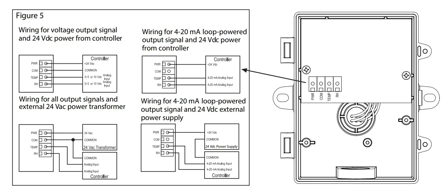
- Connect the plus DC or the AC voltage hot side to the PWR terminal. For voltage output or AC power, the supply Common is connected to the COM terminal.The device is reverse voltage protected and will not operate if connected backward. It has a half-wave power supply so the supply Common is the same as the signal Common. See Figure 5.
- The analog outputs are designated as TEMP and RH by each terminal. Check the controller Analog Input to determine the proper connection before applying power. See Figure 5.
SPECIFICATIONS
| Humidity Sensor Type | Thermoset Polymer-based capacitive |
| Accuracy | ±2, 3, or 5% RH, (5% to 95% RH) |
| Measurement Range | 0 to 100% RH |
| Hysteresis | ±1.5% RH maximum |
| Repeatability | ±0.5% RH typical |
| Linearity. | ±0.5% RH typical |
| Sensor Response Time | 15 seconds typical |
| Stability | ±1% RH typical at 50% RH in 5 yrs. |
| Temperature Sensor Type | 1000Ω Platinum, IEC 75, 385 Alpha, thin film |
| Sensor Accuracy | ±0.1% of span |
| Operating Temperature | -40 to 50˚C (-40 to 122˚F) |
| Operating Humidity | 0 to 95% RH non-condensing |
| Power Supply | 18 to 35 Vdc, 15 to 26 Vac |
| Consumption | 22 mA maximum |
| Input Voltage Effect | Negligible over the specified operating range |
| Protection Circuitry | Reverse voltage protected & output limited |
| Output Signals | 4-20 mA, 0-5 or 0-10 Vdc |
| Output Drive at 24 Vdc | 550 ohms max for current output,10K ohms min for voltage output |
| Internal Adjustments | Clearly marked ZERO and SPAN ports |
| Wiring Connections | Screw terminal block (14 to 22 AWG) |
| Enclosures | Grey polycarbonate with gasket, UL94-V0 IP65 117 W x 102 H x 53 D mm (4.6” x 4.0” x 2.1”) |
| Weight | 220g (7.8 oz) including Probe |
| Country of Origin | .Canada |
DIMENSIONS
 report this ad
![]()
![]() Copyright © Greystone Energy Systems, Inc.All Rights ReservedPhone: +1 506 853 3057Web: www.greystoneenergy.comIN-GE-HTOSXXX-01 04/20PRINTED IN CANADA
Copyright © Greystone Energy Systems, Inc.All Rights ReservedPhone: +1 506 853 3057Web: www.greystoneenergy.comIN-GE-HTOSXXX-01 04/20PRINTED IN CANADA
References
[xyz-ips snippet=”download-snippet”]