
Walk Behind Broadcast Spreader Assembly Instructions
3042650 Steel Frame

FULL ONE YEAR WARRANTY
Manufacturer will repair, or at manufacturer’s discretion will replace any part of this salt spreader which proves to be defective in workmanship or material under normal use for a period of one year from the date of delivery to the original purchaser. Any cost incurred in returning the product to the supplier is the responsibility of the consumer.
EXCLUSIONS
Manufacturer shall not be liable for special, incidental, or consequential damages, or for damages resulting from lack of necessary maintenance, from misuse, abuse, acts of God, or alteration of the product. Some states do not allow the exclusion or limitation of incidental or consequential damages, so the above limitation or exclusion may not apply to you.
TOOLS NEEDED FOR ASSEMBLY
- (2) 10mm Wrenches
- (2) 1/2 in Wrenches
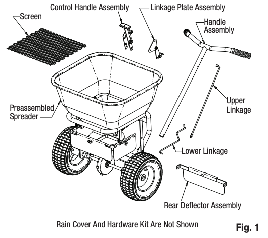
Contents of Box – Figure 1
Check contents of box against the parts list to make sure all components are included. When ordering replacement or spare parts refer to the parts list for part numbers.
Attaching the Handle, Linkage Plate Assembly, and Lower Linkage – Figures 2 – 5
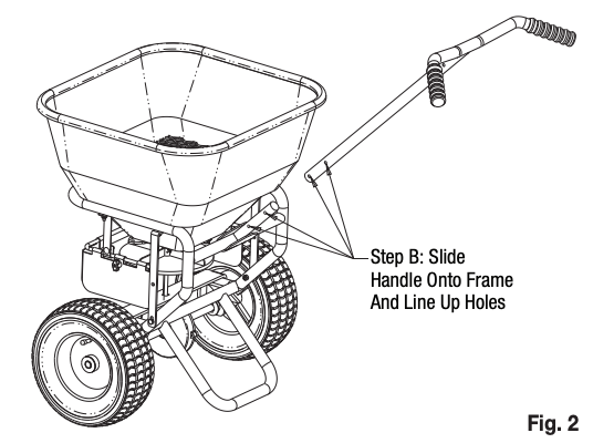
A. Remove contents from box and place the preassembled portion of the spreader upright on its wheels
B. Slide the Handle onto the spreader frame & line up the holes
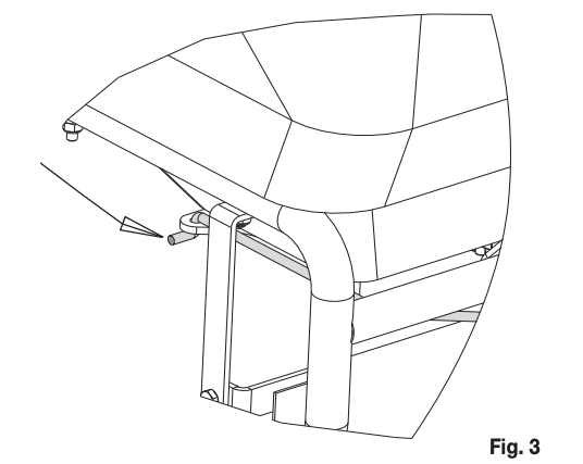
C. Carefully insert the Lower Linkage into the Restrictor Plate underneath the Hopper as shown. (The Lower Linkage has two bent ends & the Upper Linkage has one threaded end).
D. Insert the other end of the Lower Linkage into the front hole on the Linkage Plate Assembly
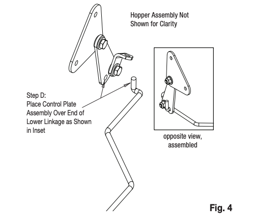
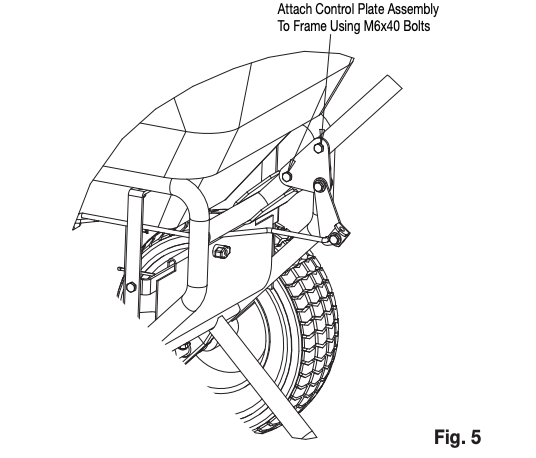
E. Attach the Linkage Plate Assembly and Handle to the Frame using two M6x40 bolts as shown (see Fig. 5 on next page). Figure 6 shows the lower linkage assembled (for reference).
NOTE: The Lower Linkage must be attached to the restrictor and the Linkage Plate Assembly before the Assembly is attached to the frame. If the Linkage Plate Assembly is attached to the Frame without the Lower Linkage, the Lower Linkage will be very difficult to assemble and may cause the restrictor plate to be broken during assembly
Attach Control Handle Assembly, Upper Linkage, & Rear Deflector – Figure 6 & 7
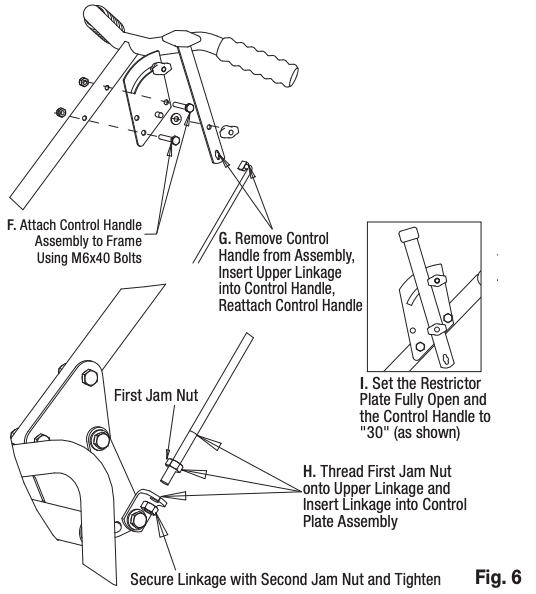
F. Mount the Control Handle Assembly to the Handle using two M6x40 bolts as shown.
G. Insert the Upper Linkage into the Control Handle as shown.
H. Thread one Jam Nut so that the Restrictor Plate underneath the Hopper is fully open when the Control Handle is at “30”. Assemble the second jam nut in this position to lock the linkage in place.
I. Verify that the Restrictor Plate may be fully closed by pushing the Control Handle forward.
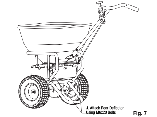
J. Using two M6x20 bolts, attach the rear deflector.
Final Assembly
A. Check And Tighten All Fasteners – Make sure the Gearbox turns freely when pushing and pulling the unit.
B. Place the Screen in the hopper.
C. Install the Rain Cover on the hopper.
Operation
- Before filling Hopper, ensure that the Restrictor Plate is fully closed and the screen is in place.
- Move and tighten the stop bolt to the desired setting.
- Begin moving forward with the spreader.
- Pull the Control Handle back to the stop bolt to open Restrictor Plate and allow material to flow.
- Before stopping, push the Control Handle forward to stop the flow.
Maintenance
- The Hopper and Spinner should be completely emptied and cleaned before storage.
- The Spreader should be washed and dried before storage.
- Check that the Restrictor Plate and Linkage move freely. Clear out any debris between the Restrictor Plate & the Hopper.
- Check that the gearbox moves freely.
- Check torque of all fasteners on a monthly basis.
Operation Notes
- The spreader is designed to be operated at a brisk walking pace (approx. 3mph). Walking slower or faster will alter the distribution pattern & amount of the material, as will the moisture content of the material & other environmental factors.
- Grease should be applied to the gear box during seasonal use, and prior to storing for the season.
![]()
WARNING
When filling hopper, make certain there are no large objects within the material. Objects larger than the openings in the Screen may cause the spreader to clog or even damage the drive system. Never leave material in the hopper when not in use.
Parts List

Bill of Material
| ITEM | PART NO. | QTY | DESCRIPTION |
| 1 | 3021435 | 1 | Frame |
| 2 | 3010874 | 1 | Handle |
| 3 | 3042704 | 1 | Hopper Assembly |
| – | 3042705 | Hopper | |
| – | 3012702 | Restrictor Plate Assembly | |
| 4 | 3012696 | 1 | Spinner Disc |
| 5 | 3035272 | 1 | Axle |
| 6 | 3008142 | 1 | Deflector Assembly |
| 7 | 3011734 | 1 | Rear Deflector Assembly |
| 8 | 3009160 | 1 | Control Handle Assembly |
| ITEM | PART NO. | QTY | DESCRIPTION |
| 9 | 3010878 | 1 | Linkage Plate Assembly |
| 10 | 3010879 | 1 | Lower Linkage |
| 11 | 3010880 | 1 | Upper Linkage |
| 12 | 3010871 | 2 | Hopper Support Bracket |
| 13 | 3014857 | 2 | Wheel |
| 14 | 3008813 | 1 | Screen |
| 15 | 3027118 | 1 | Gearbox Assembly |
| 16 | 3015357 | 1 | Hardware Bag |
| 17 | 3007873 | 1 | Agitator Pin |
| 18 | 3012704 | 2 | Axle Bushing |
References
[xyz-ips snippet=”download-snippet”]