GW INSTEK GDS-1000B Series Digital Storage Oscilloscope
SAFETY INSTRUCTIONS
This section contains the basic safety symbols that may appear on the accompanying User Manual CD or on the instrument. For detailed safety instructions and precautions, please see the Safety Instructions chapter in the user manual CD.
Safety SymbolsThese safety symbols may appear in the user manual or on the instrument.
Power Cord for the United KingdomWhen using the instrument in the United Kingdom, make sure the power cord meets the following safety instructions.NOTE: This lead/appliance must only be wired by competent persons.WARNING: THIS APPLIANCE MUST BE EARTHED IMPORTANT: The wires in this lead are coloured in accordance with the following code:
As the colours of the wires in main leads may not correspond with the coloured marking identified in your plug/appliance, proceed as follows:The wire which is coloured Green & Yellow must be connected to the Earth terminal marked with either the letter E, the earth symbol or coloured Green/Green & Yellow.The wire which is coloured Blue must be connected to the terminal which is marked with the letter N or coloured Blue or Black.The wire which is coloured Brown must be connected to the terminal marked with the letter L or P or coloured Brown or Red.If in doubt, consult the instructions provided with the equipment or contact the supplier.This cable/appliance should be protected by a suitably rated and approved HBC mains fuse: refer to the rating information on the equipment and/or user instructions for details. As a guide, a cable of 0.75mm2 should be protected by a 3A or 5A fuse. Larger conductors would normally require 13A types, depending on the connection method used.Any exposed wiring from a cable, plug or connection that is engaged in a live socket is extremely hazardous. If a cable or plug is deemed hazardous, turn off the mains power and remove the cable, any fuses and fuse assemblies. All hazardous wiring must be immediately destroyed and replaced in accordance to the above standard.
GETTING STARTED
The Getting started chapter introduces the oscilloscope’s main features, appearance, and set up procedure.
Features
- 7 inch, 800 X 480 TFT WVGA display.
- Models available from 50MHz to 100MHz.
- Real-time sampling rate of 1GSa/s, max.
- Record length: 10M points record length.
- Waveform capture rate of 50,000 waveforms per second.
- Vertical sensitivity: 1mV/div~10V/div.
- On-screen Help.
- 32 MB internal flash disk.
- Go-NoGo app.
- Remote Disk app (4 ch. only).
Interface
- USB host port: front panel, for storage devices.
- USB device port: rear panel, for remote control or printing (to PictBridge compatible printers).
- Probe compensation output with selectable output frequency (1kHz ~ 200kHz).
- Ethernet port (GDS-1054B, GDS-1074B, GDS-1104B only).
- Calibration output.
Package Contents and Accessories
Standard Accessories
Item: Model NumberUser manual: CDQuick Start Guide (this document)Passive Probe; 70 MHz for GTP-070B-4 GDS-1054B, GDS-1072B, GDS-1074BPassive Probe; 100 MHz for GTP-100B-4 GDS-1102B, GDS-1104BPower Cord x1 Region Dependent
Display and Panel Overview
Display Overview
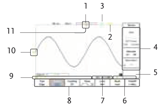
Description
- Memory Bar
- Trigger Status
- Acquisition Status
- Side Menu
- Waveform Frequency
- Trigger Configuration
- Horizontal status
- Bottom Menu
- Channel Status
- Channel/Reference/ Math Indicators
- Horizontal Position
Front Panel
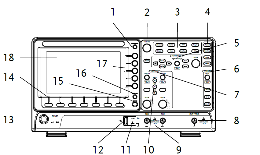
Description
- Hardcopy key
- Variable knob and Select key
- Function keys
- Autoset, Run/Stop, Single & Default keys
- Horizontal and Search* controls
- Trigger controls
- Vertical controls
- EXT trigger input (2CH only)
- Analog channel inputs
- Math, Reference & Bus* keys
- Probe calibration output
- USB Host port
- Power button
- Bottom menu keys
- Option* key
- Menu off key
- Side menu keys
- LCD
*The Bus, Search and Option keys are not available on the GDS-1000B.
Rear Panel

Description
- USB device port
- LAN port (GDS-1054B, GDS-1074B, GDS- 1104B only)
- Go-NoGo output
- Key lock slot
- Power input socket
- Fan
- Calibration output
Setting up the Oscilloscope
This section describes how to set up the oscilloscope properly including setting the stand, installing the optional modules and compensating the probe.
Tilting the Stand
The GDS-1000B has two adjustable tabs at the front that can be used to position the instrument into two preset orientations.
- Pull the tabs out to lean the scope back.
- Push the tabs under the casing to stand upright.


Probe Compensation
This section describes how to connect a signal, adjust the scale, and compensate the probe. Before operating the GDS-1000B in a new environment, run these steps to make sure the instrument performs at its full potential.
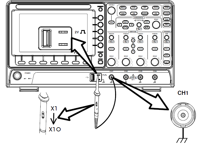
- Press the key to reset the system to the factory settings.
- Connect the probe to the Channel 1 input and to the probe calibration output. This output provides a 2Vp-p, 1kHz square wave for signal compensation by default.
- Set the probe attenuation voltage to x10.
- Press the autoset key.
- A square waveform will appear in the center of the display.
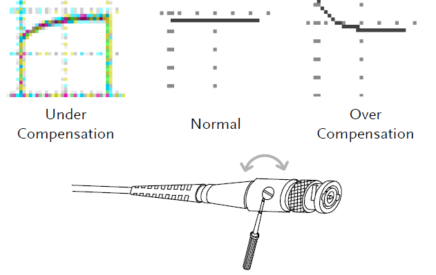
- Press the display key and select the Vector
- Turn the adjustment point on the probe to flatten the square waveform edge.
- Setting up the oscilloscope is complete. You may start to use the oscilloscope.
SPECIFICATIONS
The specifications apply when the oscilloscope is powered on for at least 30 minutes under +20°C~+30°C.
Model Specific Specifications
GDS-1054B
- Bandwidth (ñ3dB) DC coupling: DC ~ 50MHz
- Channels 4
- Rise Time 7ns
- Bandwidth Limit 20MHz
GDS-1072B & GDS-1074B
- Bandwidth (ñ3dB) DC coupling: DC ~ 70MHz
- Channels 2 + EXT (GDS-1072B) 4 (GDS-1074B)
- Rise Time 5ns
- Bandwidth Limit 20MHz
GDS-1102B & GDS-1104B
- Bandwidth (ñ3dB) DC coupling: DC ~ 100MHz
- Channels 2 + EXT (GDS-1102B) 4 (GDS-1104B)
- Rise Time 3.5ns
- Bandwidth Limit 20MHz
Common Specifications
- Resolution 8 bit :1mV~10V/div
- Input Coupling AC, DC, GND
- Input Impedance 1MΩ// 16pF approx
- DC Gain Accuracy 1mV: ±4% full scale >2mV: ±3% full scale
- Polarity Normal & Invert
- Maximum Input Voltage 300Vrms, CAT I
- Offset Position Range 1mV/div: ±1.25V 2mV/div ~ 100mV/div: ±2.5V 200mV/div ~ 10V/div: ±125V
- Waveform Signal Process: +, -, ×, ÷, FFT, FFTrms, User defined expression FFT: Spectral magnitude. Set FFT Vertical Scale to Linear RMS or dBV RMS, and FFT Window to Rectangular, Hamming, Hanning, or Blackman-Harris
External Trigger
- Range ±15V
- Sensitivity DC ~ 100MHz Approx. 100mV
- Input Impedance 1MΩ±3% ~ 16pF
Trigger
- Source: CH1, CH2, CH3*, CH4*, Line, EXT** *4 channel models only. **2 channel models only.
- Trigger Mode: Auto (supports Roll Mode for 100 ms/div and slower), Normal, Single
- Trigger Type: Edge, Pulse Width(Glitch), Video, Pulse Runt, Rise & Fall, Timeout, Alternate, Event- Delay (1~65535 events), Time- Delay (Duration: 4ns~10s)
- Holdoff range 4ns to 10s
- Coupling AC, DC, LF rej., HF rej., Noise rej.
- Sensitivity 1 div
Horizontal
- Timebase Range 5ns/div ~ 100s/div (1-2-5 increments) ROLL: 100ms/div ~ 100s/div
- Pre-trigger 10 div maximum
- Post-trigger 2,000,000 div maximum
- Timebase Accuracy ±50 ppm over any ≥ 1ms time interval
- Real Time Sample Rate 1GSa/s, max.
- Record Length Maximum 10Mpts
- Acquisition Mode Normal, Average, Peak Detect, Single
- Peak Detection 2ns (typical)
- Average Selectable from 2 to 256
X-Y Mode
- X-Axis Input Channel 1; Channel 3* *4 channel models only.
- Y-Axis Input Channel 2; Channel 4* *4 channel models only.
- Phase Shift ±3° at 100kHz
Cursors and Measurement
- Cursors Amplitude, Time, Gating available; Unit: seconds(s), Hz(1/s), Phase(degree), Ration(%)
- Automatic Measurement: 36 sets: Pk-Pk, Max, Min, Amplitude, High, Low, Mean, Cycle Mean, RMS, Cycle RMS, Area, Cycle Area, ROVShoot, FOVShoot, RPREShoot, FPREShoot, Frequency, Period, RiseTime, FallTime, +Width, – Width, Duty
- Cycle, +Pulses, – Pulses, +Edges, -Edges, FRR, FRF, FFR, FFF, LRR, LRF, LFR, LFF, Phase
- Cursors measurement Voltage difference between cursors ( ΔV) Time difference between cursors ( ΔT)
- Auto counter 6 digits, range from 2Hz minimum to the rated bandwidth.
Control Panel Function
- Autoset: Single-button, automatic setup of all channels for vertical, horizontal and trigger systems, with undo Autoset
- Save Setup: 20set
- Save Waveform: 24set
Display
- TFT LCD Type 7″ TFT WVGA color display
- Display Resolution 800 horizontal × 480 vertical pixels (WVGA)
- Interpolation Sin(x)/x
- Waveform Display Dots, vectors, variable persistence (16ms~4s), infinite persistence
- Waveform Update Rate 50,000 waveforms per second, maximum
- Display Graticule 8 x 10 divisions
- Display Mode YT, XT
Interface
- USB Port USB 2.0 High-speed host port X1, USB High-speed 2.0 device port X1
- Ethernet Port RJ-45 connector, 10/100Mbps with HP Auto-MDIX. (Only for the GDS-1054B, GDS-1074B, GDS-1104B)
- Go-NoGo BNC 5V Max/10mA TTL open collector output
- Kensington Style Lock Rear-panel security slot connects to standard Kensington-style lock
Miscellaneous
- Multi-language menu Available
- Operation Environment Temperature: 0°C to 50°C Relative Humidity: ≤ 80% at 40°C or below; ≤ 45% at 41°C ~ 50°C
- On-line help Available
- Dimensions 384mm x 208mm x 127.3mm
- Weight 2.8kg
EC Declaration of Conformity
We GOOD WILL INSTRUMENT CO., LTD. declare that the below mentioned product Type of Product: Digital Storage Oscilloscope Model Number: GDS-1104B, GDS-1102B, GDS-1174B, GDS-1072B,are herewith confirmed to comply with the requirements set out in the Council Directive on the Approximation of the Law of Member States relating to the EMC: 2014/30/EU, LVD: 2014/35/EU, WEEE: 2012/19/EU and RoHS: 2011/65/EU. For the evaluation regarding the Electromagnetic Compatibility and Low Voltage Directive, the following standards were applied:
| ◎ EMC | |
| EN 61326-1:
EN 61326-2-1: |
Electrical equipment for measurement, control and laboratory use –– EMC requirements (2013) |
| Conducted & Radiated Emission EN 55011: 2016 | Electrical Fast Transients EN 61000-4-4: 2012 |
| Current Harmonics EN 61000-3-2: 2014 | Surge Immunity EN 61000-4-5: 2014 |
| Voltage Fluctuations EN 61000-3-3: 2013 | Conducted Susceptibility EN 61000-4-6: 2014 |
| Electrostatic Discharge EN 61000-4-2: 2009 | Power Frequency Magnetic Field EN 61000-4-8: 2010 |
| Radiated Immunity
EN 61000-4-3: 2006+A1: 2008+A2: 2010 |
Voltage Dip/ Interruption EN 61000-4-11: 2004 |
| Low Voltage Equipment Directive 2014/35/EU | |
| Safety Requirements | EN 61010-1: 2010 (Third Edition)
EN 61010-2-030: 2010 (First Edition) |
 report this ad
References
[xyz-ips snippet=”download-snippet”]