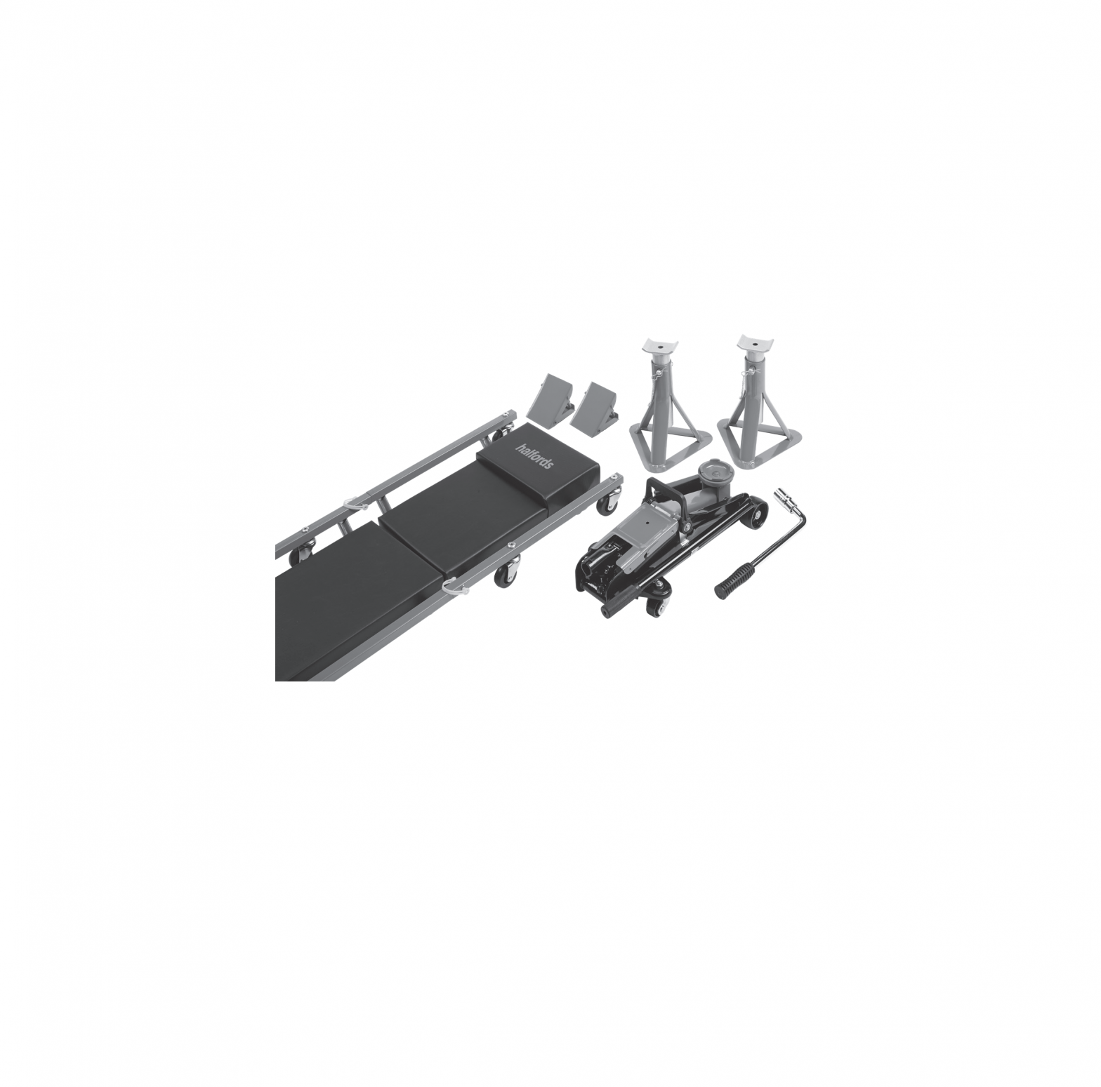
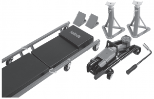
halfords 5 Piece Lifting Kit
INTRODUCTION
For your safety please read this manual before using any lifting equipment ensuring you fully understand its operation and the safety procedures to be observed. Ensure this manual is retained for future reference and that new users of this product read and understand the content before they use the product. For your safety please read this manual before using any lifting equipment ensuring you fully understand its operation and the safety procedures to be observed.Ensure this manual is retained for future reference and that new users of this product read and understand the content before they use the product.
GUARANTEE
This product is guaranteed by Halfords against manufacturing defects for a period of 12 months from the date of purchase. This does not affect your statutory rights.Should you experience a problem please return the product, together with the receipt and this manual to your nearest Halfords store.
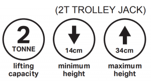
2 TONNE HYDRAULIC TROLLEY JACK
WARNINGFailure to comply with these instructions can cause serious injury and damage to the vehicle. If you are in any way unsure, do not attempt to use this product and consult a qualified mechanic
- Read and understand instruction manuals fully before use. Use only as specified.
- Never overload this jack by exceeding its rated safe working load.
- Check vehicle owner’s manual for gross vehicle weight.
- This jack is for lifting purposes only.
- Ensure all body parts are kept clear of the jack and vehicle during the raising and lowering operation.
- After lifting the vehicle, support immediately with properly rated axle stands.
- Never work on or under a vehicle without using properly rated axle stands.
- Only use on solid, even and level ground with the wheels chocked, the vehicle in gear and its hand brake on.
- Ensure that the wheels of the jack are rolling freely, all 4 wheels of the jack remain on the ground during operation.
- Always ensure that the load is centred on the jack saddle. Off centre loads can become unstable and slip resulting in possible damage or injury.
- Only use jacking points specified by your vehicle manufacturer. Some vehicles may require a manufacturer specific adaptor. Check vehicle handbook for location and details.
- Ensure vehicle jacking points are in good, sound condition with no corrosion etc.
- Do not attempt to move or dolly the vehicle whilst on the jack.
- This jack is not designed to support extensions, cradles etc.
- Do not attempt to modify this jack in any way.
- Do not attempt to use this jack if you suspect a fault.
- Do not start the vehicle in its raised position.
- Do not attempt to enter the vehicle and ensure all passengers are out of the vehicle when using this product.
PARTS OF THE JACK

- Front castor
- Saddle
- Handle fork
- Handle
- Release valve
- Handle storage hook
- Rear castor assembly
- Top cover plate
FOR YOUR SAFETY AND TO PREVENT INJURY:

BEFORE FIRST USE
Air may become trapped in the hydraulic system during transit. To purge air:
- Open the release valve by rotating the handle counter clockwise one full turn.
- Place the handle in the handle socket and pump about 4 full strokes to purge the air from the pump and valving.
- Close the release valve. Pump the handle until the jack has reached full extension. Continue to pump several times to purge air from under the ram.
- Open the release valve and push ram into its lowest position. Close the release valve and operate normally.
Note: If the jack responds immediately to pump action, it is free of air and ready for operation. If not, repeat procedure
INSPECTION BEFORE EACH USEVisual inspection should be made before each use of the jack. Check for leaking hydraulic fluid, cracked welds and damaged, loose or missing parts.Any jack which appears to be damaged in any way, found to be badly worn, operates abnormally, or has been subjected to an abnormal load or shock MUST NOT BE USED.
OPERATING INSTRUCTIONS
IMPORTANT: Only use jacking points specified by your vehicle manufacturer. Some vehicles may require a manufacturer specific adaptor. Check vehicle handbook for location and details.
TO MOVE:Place handle in operating lever. Do not move the jack when handle is on the release valve as this may cause damage to the jack. Do not attempt to move the jack whilst under load.
TO LIFT THE VEHICLE:
- Park the vehicle on solid, even and level ground. Apply the hand brake, place the vehicle in gear (P if automatic) and chock the wheels that will remain on the ground.
- Using the jack handle as a wrench, turn the release valve clockwise until fully tightened, DO NOT OVERTIGHTEN.
- Place the handle into the operating lever and position the jack under the jacking point of the vehicle. Pump up and down until the saddle reaches the jacking point. Before lifting, ALWAYS ensure that the load point is centred on the jack saddle and cannot slip. Off centre loads can become unstable and slip resulting in damage or injury.
- Once secure on the jacking point, begin to raise load to desired height by pumping the handle.IMMEDIATELY support the vehicle by placing properly rated axle stands under a strong, stable point on the vehicle. Consult the vehicle owner’s manual and axle stand instruction manual for guidance. DO NOT CRAWL UNDER VEHICLE WHILE LIFTING VEHICLE OR PLACING OR REMOVING JACK STANDS!
- Once the axle stands are properly located, VERY SLOWLY turn the release valve anticlockwise until the vehicle begins to lower onto the stands. Lower the vehicle slowly so as not to shock load the jack stands.
- BEFORE GOING UNDER THE VEHICLE ensure that all axle stands and chocks are correctly in place and there is no chance of the vehicle becoming unstable.
TO LOWER THE VEHICLE:Once repairs are completed raise the vehicle slightly, remove the axle stands and using the handle as a wrench, VERY SLOWLY turn the release valve anti-clockwise until the vehicle begins to lower.CAUTION: Ensure all body parts are kept clear of the jack and vehicle during the raising and lowering operation.
MAINTENANCE, CARE AND LUBRICATION
- This jack contains no user serviceable parts. Any modification will render the jack unsafe.
- All moving joints require lubricating often. Lubricate all linkages, pivot points and castor wheels using a grease gun.
- Regularly check the plunger, main piston and linkages for signs of corrosion. Clean any light surface corrosion with a suitable maintenance spray. If the corrosion is deeper than surface do not attempt to use.
- When not in use Keep the jack stored on all 4 wheels with the arm and plunger all the way down to prevent corrosion.
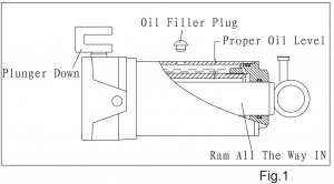
TO ADD OIL
IMPORTANT When adding or replacing oil, ONLY use a quality hydraulic oil adhering to ISO VG 32 or similar. DO NOT use brake fluid, transmission fluid, alcohol, glycerin, detergent motor oil, or dirty oil etc. as improper fluid will cause serious internal damage to jack making it unsafe to use.
- Place the jack on level ground with the lifting arm and plunger fully lowered.
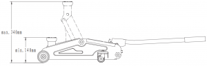
- Remove the top cover plate and clean the surrounding area of the oil filler plug and remove ensuring that no dirt etc falls into the unit (see Fig.1).

- Oil should be filled to level indicated in the diagram. If low, add hydraulic oil as required
Maintenance and inspection: The owner and/ or user must maintain and inspect the jack in accordance with the manufacturer’s instructions.
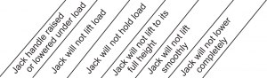 |
Trouble Shooting Check List | |||
|
⚫ |
⚫ |
⚫ |
Internal valves are not fully seated:(l) Lower the ram, close the release valve and remove oil filler plug.(II) Pull up the arm by hand to its full height.(III) Open the release valve, close the ram and replace oil filler plug. | |
|
⚫ |
⚫ | ⚫ |
⚫ |
The jack could be air locked:(I) Open the release valve and remove oil filler plug.(II) Pump handle for 6 full strokes and close the release valve. Re-fit the oil filler plug. |
|
⚫ |
⚫ |
The jack could be over filled with oil: See maintenance instructions for correct procedure. | ||
|
⚫ |
⚫ |
The jack oil level may be low: Remove the oil filler plug and refill with hydraulic jack oil to the correct level when the ram is fully down, see maintenance instructions – DO NOT USE BRAKE FLUID. | ||
|
⚫ |
⚫ |
The release valve is not tightly closed: Close release valve by tuning it fully clockwise. | ||
|
⚫ |
Unit needs lubrication – oil external moving parts, see maintenance instructions. |
SPECIFICATIONS
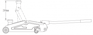

| Low height | 14cm |
| High height | 34cm |
| Saddle diameter | 6.7cm |
| Handle length | 42cm |
| Base length | 45cm |
| Chassis width | 20.5cm |
All dimensions are approximate.
2 TONNE AXLE STANDS
WARNINGFailure to comply with these instructions can cause serious injury and damage to the vehicle. If you are in any way unsure, do not attempt to use this product and consult a qualified mechanic.
- Read and understand instruction manuals fully before use. Use only as specified.
- Never overload these axle stands by exceeding the rated safe working load.
- Check vehicle owners’ manual for gross vehicle weight.
- Use no more than one pair of stands.
- Ensure all body parts are kept clear of the jack and vehicle when positioning and removing the axle stands.
- After lifting the vehicle, support immediately with properly rated axle stands.
- WARNING! Never work on or under a vehicle without using properly rated axle stands.
- Only use on solid, even and level ground with the wheels chocked, the vehicle in gear and its handbrake on.
- Always ensure that the load is centred and secure on the axle stand top saddle. Off centre loads can become unstable and slip resulting in possible damage or injury.
- Ensure that each stand is securely located under a strong, stable point on the vehicle: consult the vehicle owners manual for guidance.
- Ensure vehicle jacking and support points are in good, sound condition with no corrosion etc.
- Do not attempt to move or dolly the vehicle whilst on the axle stands or jack.
- Do not attempt to modify these axle stands in any way.
- Upper and lower columns to be used as a pair as supplied.
- Do not attempt to use if you suspect a fault.
- Do not start the vehicle in its raised position.
- Do not attempt to enter the vehicle and ensure all passengers are out of the vehicle when using this product.
- Take care when using on a three-wheeled vehicle or trailer.
PARTS OF THE AXLE STAND

- Upper support column
- Lower support column
- Locating pin
- Split pin
- Top saddle
INSPECTION BEFORE EACH USE
Visual inspection should be made before each use of the axle stands. Check for cracked welds and damaged, loose or missing parts.Any axle stand which appears to be damaged in any way, found to be badly worn, operates abnormally, or has been subjected to an abnormal load or shock MUST NOT BE USED
MAINTENANCE
Periodically inspect each stand. Ensure all parts move freely. Do not apply oil or grease to any part of this product. If rust appears, sand affected area and cover with suitable utility paint.
STORAGE
Store stands in an upright position in a clean, dry area.
SPECIFICATION

All dimensions are approximate.
OPERATING INSTRUCTIONS
TO SUPPORT VEHICLE:
- Pull the upper column out from the lower column.
- Insert the locating pin through the holes in both upper and lower columns.
- Secure the locating pin by inserting the clip pin into it.
- Carefully position the axle stands so that the load will contact the centre of the top saddle.
- Always use axle stands in pairs and only on those parts of the vehicle which can support the load. Please consult the vehicle owner’s manual for the lift and support points.
NOTE: The stands must only be positioned on a hard level surface when operational. The rated load of 2 Tones per pair must not be exceeded under any circumstances. Centre load on the top saddle. Use as a matched pair to support one end of a vehicle only.
TO LOWER LOAD:
- Raise vehicle clear of stands.
- Carefully lower the stands to lowest position.
- Remove stands then carefully lower vehicle to the ground.
- Ensure that all tools, equipment and personnel are clear of the vehicle before lowering the load.
PADDED CAR CREEPER
WARNINGFailure to comply with these instructions can cause serious injury. If you are in any way unsure, do not attempt to use this product and consult a qualified mechanic.
- Read and understand instruction manuals fully before use. Use only as specified.
- Never overload the creeper by exceeding its weight limit of 120Kg.
- Do not stand on the creeper.
- Only use the creeper on solid, even and level ground.
- Do not attempt to modify the creeper in any way.
- Follow instructions and observe warnings for other lifting products being used with the creeper.
- The creeper is solely for the purpose of improving comfort and access to the underside of a vehicle. It should not be used for any other purpose.
- Use extreme caution when working on or around a vehicle that has been lifted to avoid possible damage or injury.
- Do not attempt to use the creeper if you suspect a fault. If the creeper stops operating properly or parts are loose, missing or broken, stop using immediately.
- Plastic will burn and can be damaged by some chemicals. Exercise care if using a naked flame or carrying out hot work. Clean any chemical spillages off the creeper immediately.
- Store the creeper in a cool, dry environment out of direct sunlight.
PARTS LIST
- Car Creeper frame sections: X2
- Castor wheels: X6
- Lock pins with locking caps: X2
- Hex Key: X1
ASSEMBLY INSTRUCTIONS
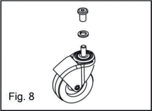
- Unscrew the top part of the castor wheels (Fig. 8) and align them with the holes in the metal frame of the creeper. Fix each castor to the frame.
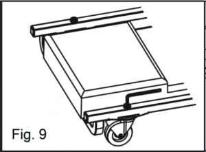
- Tighten the screws with the hex key provided (Fig. 9).
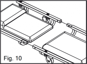
- Connect the two sections of the creeper together and ensure the pin retaining holes are aligned (Fig. 10).
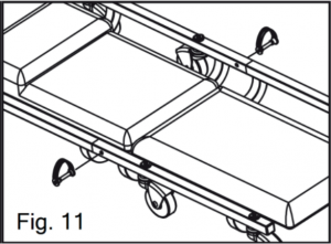
- Insert the lock pin through the aligned holes and press the plastic cap over the head of the locking pin (Fig. 11).
PADDED CAR CREEPER
SPECIFICATIONS
| Description | Padded Car Creeper |
| Model | TR6454B |
| Overall Size | 89cm x 39cm x 9cm approx. |
MAINTENANCE
Periodically inspect for corrosion, damage, cracking, bent or missing parts. Stop using this product if any of these conditions are found. Rectify before using.Do not expose to prolonged wet or corrosive conditions.Clean all surfaces after each use with a dry clean cloth and store in a dry, protected environment.Keep work area clean. Cluttered work areas invite injury.FAILURE TO HEED THIS WARNING MAY RESULT IN PERSONAL INJURY AND/ORPROPERTY DAMAGE!
WHEEL WRENCH WITH 17/19mm SOCKET
INSTRUCTIONS FOR USE:
- Before changing a wheel, ensure the handbrake is on and the car is on level ground.Use hazard light, or warning triangle if changing a wheel on roadside.
- Before jacking up the car, loosen the wheel nuts.
- Jack up the car following the manufacturer’s recommended advice and support the car immediate by other appropriate means.
- Spin off the loosen wheel nuts.
- Remove the wheel, clean the threads and oil them lightly to prevent rusting.
- Fit the spare wheel and partially tighten the nuts before lowering the jack.
- When the car has been lowered, fully tighten the wheel nuts.
- Always tighten the wheel nuts in a diagonal sequence.
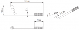
SPECIFICATIONS
| Length | 32.8cm |
| Width | 10cm |
STEEL WHEEL CHOCKS
WARNINGFailure to comply with these instructions can cause serious injury and damage to the vehicle. If you are in way unsure, do not attempt to use this product and consult a qualified mechanic.
- Read and understand instruction manuals fully before use. Use only as specified.
- Never overload these wheel chocks by exceeding their safe working load (2000Kg) or using with wheels over 16’’ in diameter.
- Check vehicle owner’s manual for gross vehicle weight.
- These wheel chocks should only be used in conjunction with lifting equipment to help provide safe and stable lifting conditions.
- Follow instructions and observe warnings for other lifting products being used with the wheel chocks.
- Foldable wheel chocks are not supporting devices and should not be used to raise or permanently support/secure a vehicle to prevent movement.
- Do not attempt to raise a vehicle by driving onto the foldable wheel chocks.
- Only use on solid, even and level ground with the wheels chocked, the vehicle in gear and its handbrake on.
- Use extreme caution when working on or around a vehicle that has been lifted to avoid possible damage or injury.
- Do not attempt to modify the wheel chocks in any way.
- Do not attempt to use the wheel chocks if you suspect a fault.
INSPECTION BEFORE EACH USE
Visual inspection should be made before each use of the wheel chocks. Check for cracked welds and damaged or missing parts.Any wheel chock which appears to be damaged in any way, operates abnormally, or has been subjected to an abnormal load or shock MUST NOT BE USED.
OPERATING INSTRUCTIONS
- Park the vehicle on solid, even and level ground. Apply the handbrake and place the vehicle in gear (P if automatic).
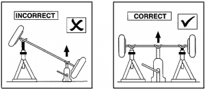
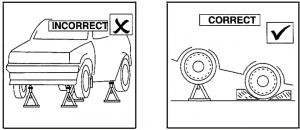
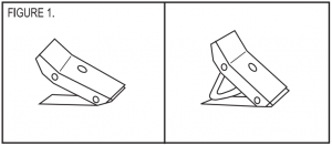
- To prevent further vehicle movement, wheels should be securely chocked with foldable wheel chocks. Refer to figure 1. The tyre to be chocked is diagonal from the wheel being lifted.
- Always use foldable wheel chocks in pairs, one pair per wheel/tyre. If more than one tyre is to be chocked, use additional pairs of foldable wheel chocks, see figure 2.
- Always position foldable wheel chocks so each is centred on the tread of the tyre. Off centre positioning could cause sudden instability, resulting in personal injury and/or property damage.
- Always place the chocks with the rubberized surface down and in contact with the ground.

Unfold and pull out support bar to stop. Lock support and bar in groove.
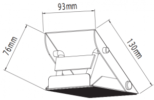
SPECIFICATIONS
| Length | 13cm |
| Width | 9.3cm |
| Unfolded (in use) height | 7.6cm |


EC DECLARATION OF CONFORMITYDate of issue: 1 September 2018 Reference batch number: ……………………………… (to be entered by the customer) Directive: Machinery Directive 2006/42/EC as amended by Directive 2009/127/EC Conforming apparatus: Product: Halfords 2 Tonne Hydraulic Trolley JackModel: TH12072Item code: 657230 Manufacturer: Halfords Limited, Icknield street Drive, Redditch, Worcestershire, B98 0DE Harmonised standards referenced or applied:EN1494:2000 + A1:2008 Mobile or movable jacks and associated lifting equipment The Supply of Machinery (Safety) Regulations 2008 Statutory instrument 2008 No.1597 The Supply of Machinery (Safety) (Amendment) Regulations 2011 Statutory instrument 2011 No.2157 Halfords Limited hereby declare that the machine described below is both in its basic design and construction and in the version marketed by us conforms to the relevant safety and health related requirements of the appropriate EC Directives. This declaration shall cease to be valid if Date of placement onto market: September 2018
|

CONTACT USHalfords Ltd, B98 0DE.www.halfords.comProduced for Halfords

References
[xyz-ips snippet=”download-snippet”]