![]()
Instruction Manual
Questions? 1-800-334-6871
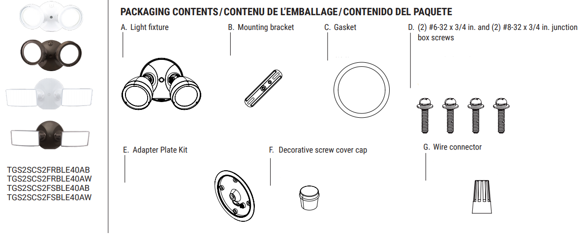
ITEMS REQUIRED
(Purchase separately)
- Phillips screwdriver
- Outdoor weatherproof silicone caulking
IMPORTANT SAFETY INSTRUCTIONS
When using product, basic precautions should always be followed, including the following:
- Heed all warnings, including below warnings AND those included on the product.
- Save these instructions and warnings.
- For outdoor use only.
- cULus LISTED for wet location.
- Disassembling your fixture will void the warranty.
- Your fixture is prewired and preassembled for easy installation.
![]() WARNING
WARNING
- Read and follow these instructions.
- Risk of fire/electric shock. If not qualified, consult an electrician.
- Disconnect power at fuse or circuit breaker before installing or servicing.
CAUTION
- Connect fixture to a 120-277 volt, 50/60 Hz power source. Any other connection voids the warranty.
- Fixture should be installed by persons with experience in household wiring or by a qualified electrician. The electrical system, and the method of electrically connecting the fixture to it, must be in accordance with the National Electrical Code and local building codes.
- Fixture designed for wall or eave mount to a junction box only. Mount fixture to a grounded, recessed-mounted standard junction box marked for use in wet locations.
- Fixture can be mounted to an outdoor-rated surface mount junction box when used with the adapter plate kit. See kit instructions for proper installation methods.
FCC DECLARATION OF CONFORMITY
This device complies with part 15 of the FCC Rules. Operation is subject to the following 2 conditions: (1) This device may not cause harmful interference, and (2) this device must accept any interference received, including interference that may cause undesired operation.NOTE: This equipment has been tested and found to comply with the limits for a Class B digital device, pursuant to part 15 of the FCC Rules. These limits are designed to provide reasonable protection against harmful interference in a residential installation. This equipment generates uses and can radiate radio frequency energy and, if not installed and used in accordance with the instructions, may cause harmful interference to radio communications. However, there is no guarantee that interference will not occur in a particular installation. If this equipment does cause harmful interference to radio or television reception, which can be determined by turning the equipment off and on, the user is encouraged to try to correct the interference by one or more of the following measures:
- Reorient or relocate the receiving antenna.
- Increase the separation between the equipment and receiver.
- Connect the equipment into an outlet on a circuit different from that to which the receiver is connected.
- Consult the dealer or an experienced radio/TV technician for help.
- This device contains transmitter module FCC ID: 2APB4-TGS2SCS2FR (IC ID: 4706B-TGS2SCS2FR)
![]() WARNING: FCC Regulations state that any unauthorized changes or modifications to this equipment not expressly approved by the manufacturer could void the user’s authorization to operate this equipment.
WARNING: FCC Regulations state that any unauthorized changes or modifications to this equipment not expressly approved by the manufacturer could void the user’s authorization to operate this equipment.
SAVE THESE INSTRUCTIONS.
FOR BEST RESULTS
- Install light 8-16 feet above the ground.
- When installing two fixtures on one switch, make sure the switch is rated for at least a 1 A inductive load.
MOUNTING AND WIRING YOUR FIXTURE
![]() WARNING: Risk of electric shock. Disconnect power at fuse or circuit breaker before installing or servicing.
WARNING: Risk of electric shock. Disconnect power at fuse or circuit breaker before installing or servicing.
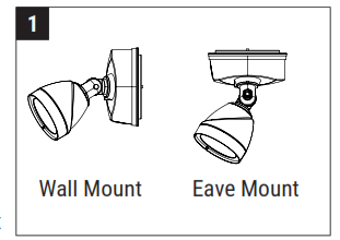
NOTE: Fixture can be wall or eave mounted (Fig. 1).
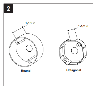
NOTE: Mounting bracket mounts to recessed mounted standard junction boxes (Fig. 2). The junction box must be at least 1-1/2 inch in depth for proper installation for the recessed mount application. For surface mount junction box installation, refer to installation instructions included with the adapter plate kit (E).
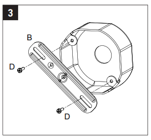
- Line up the slots on the mounting bracket (B) with the holes on your junction box. Using either (2) #6 screws or (2) #8 screws (D) (depending on the size of the holes in your junction box), attach the mounting bracket (B) to your junction box (Fig. 3). Be sure the mounting bracket is installed with the funnel for the central mounting screw going into the junction box.

- Make the electrical connection between the ground wire on the mounting bracket and the ground wire inside of the junction box.
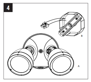
- Disconnect the male connector in the back of the fixture. Insert the junction box wires to the male connector while ensuring the hot wire (black) and neutral wire (white) are connected to the corresponding black and white connections on the male connector. (Fig. 4)Note: Be sure these are solid wires and stripped 3/8″.
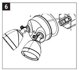
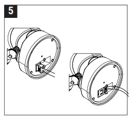
- Plug the male connector into the female connector through the gasket (C). Rotate the connector so it is recessed within the back surface of the fixture. (Figs. 5 & 6)
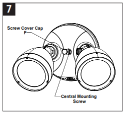
- Attach fixture (A) to the mounting bracket (B) using the central mounting screw that is already installed in the fixture. Be sure no loose wires remain to stick out from underneath the cover plate. Insert the decorative screw cover cap (F) into the screw hole on the cover plate for a finished appearance (Fig. 7).
- Adjust light fixture to the desired position by loosening the thumbscrew on the upper arm. Move the head to aim and retighten the thumbscrew.
- Apply silicone caulk around the edges of the canopy to provide a watertight seal from rain and moisture.
- Turn on power at the main fuse/breaker box.
Supplier’s Declaration of Conformity47 CFR § 2.1077 Compliance Information
Unique Identifier: Security Gen 3 LightResponsible Party – U.S. Contact InformationCooper Lighting Solutions1121 Highway 74 SPeachtree City, GA30269www.cooperindustries.com/content/public/en/lighting.htmlFCC Compliance StatementThis device complies with Part 15 of the FCC Rules. Operation is subject to the following two conditions: (1) This device may not cause harmful interference, and (2) this device must accept any interference received, including interference that may cause undesired operation.
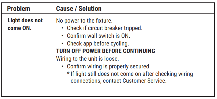
TROUBLESHOOTING
5-YEAR LIMITED WARRANTY
THE FOLLOWING WARRANTY IS EXCLUSIVE AND IN LIEU OF ALL OTHER WARRANTIES, WHETHER EXPRESS, IMPLIED, OR STATUTORY INCLUDING, BUT NOT LIMITED TO, ANY WARRANTY OF MERCHANTABILITY OR FITNESS FOR ANY PARTICULAR PURPOSE. Cooper Lighting Solutions warrants to customers that, for a period of five years from the date of purchase, Cooper Lighting Solutions products will be free from defects in materials and workmanship. The obligation of Cooper Lighting Solutions under this warranty is expressly limited to the provision of replacement products. This warranty is extended only to the original purchaser of the product. A purchaser’s receipt or other proof of date of original purchase acceptable to Cooper Lighting Solutions. This is required before warranty performance shall be rendered. This warranty does not apply to Cooper Lighting Solutions products that have been altered or repaired that have been subjected to neglect, abuse, misuse, or accident (including shipping damages).This warranty does not apply to products not manufactured by Cooper Lighting Solutions which have been supplied, installed, and/or used in conjunction with Cooper Lighting Solutions products. Damage to the product caused by replacement bulbs or corrosion or discoloration of brass components are not covered by this warranty.
LIMITATION OF LIABILITY:IN NO EVENT SHALL COOPER LIGHTING SOLUTIONS BE LIABLE FOR SPECIAL, INDIRECT, INCIDENTAL, OR CONSEQUENTIAL DAMAGES (REGARDLESS OF THE FORM OF ACTION, WHETHER IN CONTRACT, STRICT LIABILITY, OR IN TORT INCLUDING NEGLIGENCE), NOR FOR LOST PROFITS; NOR SHALL THE LIABILITY OF COOPER LIGHTING SOLUTIONS FOR ANY CLAIMS OR DAMAGE ARISING OUT OF OR CONNECTED WITH THESE TERMS OR THE MANUFACTURE, SALE, DELIVERY, USE, MAINTENANCE, REPAIR OR MODIFICATION OF COOPER LIGHTING SOLUTIONS PRODUCTS, OR SUPPLY OF ANY REPLACEMENT PARTS, THEREFORE, EXCEED THE PURCHASE PRICE OF COOPER LIGHTING SOLUTION PRODUCTS GIVING RISE TO A CLAIM. NO LABOR CHARGES WILL BE ACCEPTED TO REMOVE OR INSTALL FIXTURES.To obtain warranty service, please contact Cooper Lighting Solutions, at 1-800-334-6871, press option 2 for Customer Service, or via e-mail and include the following information:
- Name, address, and telephone number
- Date and place of purchase
- Catalog and quantity purchase
- Detailed description of the problem
All returned products must be accompanied by a Return Goods Authorization Number issued by the Company and must be returned freight prepaid. Any product received without a Return Goods Authorization Number from the Company will be refused. Cooper Lighting Solutions is not responsible for merchandise damaged in transit. Repaired or replaced products shall be subject to the terms of this warranty and are inspected when packed. Evident or concealed damage that is made in transit should be reported at once to the carrier making the delivery and a claim filed with them.
Reproductions of this document without the prior written approval of Cooper Lighting Solutions are strictly prohibited.For assistance, call 1-800-334-6871 or e-mail us at Printed in China
QUICKSTART GUIDE
Getting started is easy.First, download & install the HALO Home app.*For installation, FAQs, troubleshooting & more, visit:BringHaloHome.com*Ensure mobile device Bluetooth is ON and near an installed /powered HALO Home device

Halo Outdoor FT18VC Instruction Manual – Halo Outdoor FT18VC Instruction Manual –
[xyz-ips snippet=”download-snippet”]