
handicare Prism Castor 2 Post Lift Stand System Instructions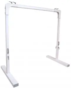
![]() CAUTION: DO NOT ATTEMPT TO USE THIS EQUIPMENT WITHOUT FIRST UNDERSTANDING THE CONTENTS OF THIS MANUAL.
CAUTION: DO NOT ATTEMPT TO USE THIS EQUIPMENT WITHOUT FIRST UNDERSTANDING THE CONTENTS OF THIS MANUAL.
Introduction
Before using this equipment, and to ensure the safe operation of your Prism Castor 2 Post Lift Stand System, carefully read this entire manual, especially the section on “Cautions”. The Prism Castor 2 Post Lift Stand System is designed to be used in conjunction with Prism Medical ceiling and portable lifts. Please refer to any user guides supplied with these components and refer to them while reviewing this manual.
Should any questions arise from reviewing this manual contact your local authorized Prism Medical Representative. Failure to comply with warnings in this manual may result in injury to either the operator, or the individual being lifted/transferred. Damage to the lift stand and/or related components may also occur. Be sure that the contents of this manual are completely understood prior to using this lift stand.
Store this manual with the documents included with the lift. Contents of this manual are subject to change.
Overview of Prism Castor 2 Post Lift Stand System
The Prism Castor 2 Post Lift Stand System is a safe, high performance and portable freestanding lift stand which, together with a track and a lift unit, functions as a stationary lift system. It is made of aluminum, which makes it light in relation to its large lifting capacity. The design is both compact and discreet while as the same time making Prism Castor 2 Post Lift Stand System one of the sturdiest freestanding lift stands on the market
Prism Castor 2 Post Lift Stand System is very easy to assemble and disassemble and therefore easy to move to locations where is a need for lifting. You can create many safe and flexible lifting solutions that are ideally adapted for all settings and users.
The following length options are available for Prism Castor 2 Post Lift Stand System:
|
Prism Castor 2 Post Lift Stand System |
|
| Part Number | Product Description |
| 343100 | Prism “Regular Track” – Length: 2083 cm [82 in] for Load: 204 kg [450 lbs] |
| 343101 | Prism “Track Plus” – Length: 5004 cm [197 in] for Load: 204 kg [450 lbs] |
| 343102 | Prism “Track Plus” – Length: 3962 cm [156 in] for Load: 283.5 kg [625 lbs] |
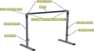
Please familiarize yourself with the components of the Prism Castor 2 Post Lift Stand System by referring to the diagram on the next page.
Components of the Prism Castor 2 Post Lift Stand System
Technical Specifications
- Post Bases, Vertical Supports and track: extruded aluminum
- Maximum Height: 244 cm [99 in] – floor to highest point
- Maximum Length: 500 cm [197 in] – depending on the track length
- Unit Weight: Up to 50 kgs [110 lbs] with no piece weighing more than 15.5 kgs [34 lbs] – depending on the track
- Maximum Load: 283.5 kgs [625 lbs]
System Dimensions
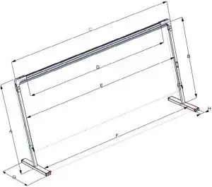
- A – Height, total: 204-250 cm [80.42-98.53 in]
- B – Lifting range, height: 192-227 cm [75.59– 89.37 in]
- C – Length, total: *237-530 cm [93.35-208.68 in]
- D – Lifting range, length: *201-493 cm [79.13-194.09 in]
- E – Length, between vertical supports: *212-504 cm [83.46-198.43 in]
- F – Distance between bases: *206-498 cm [81.10-196.06 in]
- G – Base length: 120 cm [47.24 in]
- H – Base width: 13 cm [5.11 in]
*Depending on the track length
![]() Cautions
Cautions
- Under no circumstance should the Prism Castor 2 Post Lift Stand System be put in control of a person who has not been properly trained in the use and care of this equipment. Failure to adhere to this warning may result in serious injury to the operator, and/or the individual being lifted/ transferred.
- The Prism Castor 2 Post Lift Stand System is not a toy. Do not use it for unsafe practices.Do not allow children to play with the stand or any of its components.
- The manufacturer’s warranty is voided if persons unauthorized by Prism Medical Ltd. will perform any work on the Prism Castor 2 Post Lift Stand System.
- There are no user serviceable parts in this system. Do not remove cover screws and don’t try to disassemble the unit, as this will VOID THE WARRANTY.
- In facilities where more than one operator will be responsible for using the Prism Castor 2 Post Lift Stand System, it is imperative that all such members are to be trained in its proper use. A training program should be established by the facility to acquaint new operators with this equipment.
- Never expose the Prism Castor 2 Post Lift Stand System directly to water. Warranty does not cover any misuse or abuse of the lift stand system.
- In any circumstances do not exceed the maximum allowable load of this lift stand. Refer to the “Technical Specifications” section of this manual, and/or the labels on the posts of the stand.
- Ensure that a clear space is maintained around the lift stand. Move any obstacles out of the way before opereating any lift on the stand.
- Do not hang anything else on the Prism Castor 2 Post Lift Stand System except the Prism Medical lifts which are suitable for the load allowed on the stand.
- The exterior of the stand should only be cleaned, disinfected and sterilized using isopropyl alcohol.Damp a cloth with isopropyl alcohol and wipe down entire exterior of the stand. No other chemicals and/or liquids should be used to clean, disinfect and sterilize it.
Assembly of Castor System
![]() Caution: Before Installing the Prism Caster System, all the components must be visually checked to ensure that there are no missing parts or unusual wear and tear. Should anything look unusual contact your local dealer prior to use. Failure to comply with this caution could result in serious injury to the operator, the individual being lifted and/or damage to the Castor system or the lift unit.
Caution: Before Installing the Prism Caster System, all the components must be visually checked to ensure that there are no missing parts or unusual wear and tear. Should anything look unusual contact your local dealer prior to use. Failure to comply with this caution could result in serious injury to the operator, the individual being lifted and/or damage to the Castor system or the lift unit.
Tools Required:
- Step Ladder
- 17 mm—Two Wrenches
- 2.5 mm Allen Key
- Torque Wrench with adaptors for 17 mm hex wrench and 2.5 mm Allen Key
- Level
Step 1:Ensure the floor that system will be placed on is level.
Step 2:Assemble Post Assemblies as shown below. Each system contains parts for two complete post assemblies. Ensure that each post is set to the same height.
| BOM ID | DESCRIPTION | Qty. |
| 1 | Connection Joint Single | 1 |
| 2 | Vertical Support Castor | 1 |
| 3 | Locking Handle Castor | 2 |
| 4 | Leg Rack Single | 1 |
| 6 | End Cover Castor | 2 |
| 7 | Threaded Rod M10-1.5 x 10⁵ | 1 |
| 8 | Nut Cap M10 | 8 |
| 9 | HHCS M10-1.5 x 85mm | 4 |
| 10 | M10 Nyloc Nut | 4 |

Ensure that item 9 is tightened to 25-35 N*m (20-25 Lb*ft).
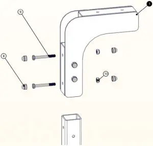 Figure 4. Detail View of Upper Post Assembly
Step 3:Assemble Track Bracket to each side of track as shown in Figure 5. Attach items one (1) and two (2) using item three (3). Brackets will slide over track as shown in Figure 6. At this point item 4 can be tightened to the specified torque value shown in Table 1.
| Item | N*m | Lb*ft |
| 3 | 2-3.5 | 1.5-2.5 |
| 4 | 4-5.5 | 3-4 |
Table 1. Torque Values
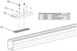 Figure 5. Detail View of Bracket Assembly
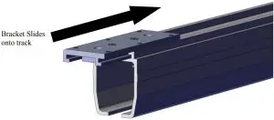 Figure 6. Assembly of Track to Bracket
Step 4:Attach track to post assembly using two (2) M10-1.25 x 20mm Hex bolts with two (2) M10 Lock Washers as shown below in Figure 7. Tighten item 4 to 25-35 N*m (20-25 Lb*Ft)
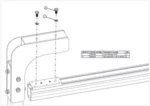 Figure 7. Detail of Assembling Track to the Post
Step 5:Once Castor System is installed use ceiling lift and lift appropriate weight for track and check for any defects in the setup.
Note: Before you start, fill out the checklist after installation. See next Page.
Castor Installation Check List
| No. | CHECKLIST | YES | NO |
| 1 | The track and Posts are free of defects. | ||
| 2 | The person/s read and understood the installation instructions | ||
| 3 | The system was installed on a level floor | ||
| 4 | Uprights are tightly secured into the post base. | ||
| 5 | All fasteners have been tightened to specified torque values | ||
| 6 | Ensure that the legs are mounted at the same height on each post. | ||
| 7 | Brackets are securely mounted to track and Connection Joint | ||
| 8 | The Required load test was performed | ||
| 9 | Annual maintenance checks have been scheduled. |
[xyz-ips snippet=”download-snippet”]