HARBINGER VARI 2308 / VARI 2310 / S12
![]()
QUICK START GUIDE: SINGLE V2308/V2310
SETTING UP / HELPFUL TIPS
- Position the VARI speaker in the desired location, and ensure the speaker is stable.
- Make sure the Power Switch is off.
- Turn Channel 1, 2, and 3 knobs to minimum.
- Turn Bass and Treble to center/straight up.
MAKING THE CONNECTIONS
- Connect sources to Channel 1, 2 and 3 input jacks as desired. (All these input jacks can be used at once, along with Bluetooth® audio input.)
CHECK SWITCHES
- Check that Mono (Normal) LED of the ROUTING function is lit.Check that Channel 1 and Channel 2 switches match sources:Mic for microphones, Guitar for acoustic guitar or pedalboard output, Line for mixers, keyboards and other electronics.
POWERING UP
- Power on any devices connected to input jacks.
- Turn up the output volume of all sources.
- Turn Channel 1, 2 and 3 knobs to desired levels.
BLUETOOTH® AUDIO INPUT
- From your Bluetooth® audio source device, look for V2308 or V2310 and select it.
- See next page for Bluetooth® Troubleshooting in case of difficulty.
FRONT LED LIGHT
- Front LED will light white to show when speaker is powered on.
- When front LED lights red, limiter is being triggered, and Channel 1, 2, and 3 knobs may need to be turned down.
FOR FLOOR MONITOR USE
- Press the button between TREBLE and BASS knob, to light the Floor Monitor LED.
- Low frequencies will be reduced, to reduce potential for feedback.
VARI Series speakers can be used as Main Speakers or Floor Monitor Speakers.
SMART STEREO WITH V2308/V2310
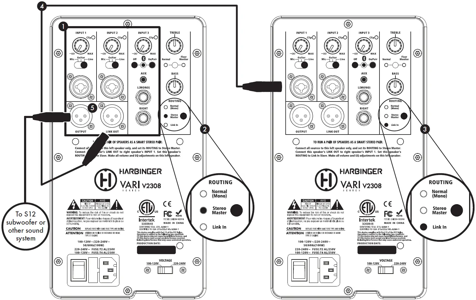
A pair of VARI 2308 or 2310 speakers can operate together as a Smart Stereo system, giving you control of the sound and volume of both speakers from the first master speaker, and optimally distributing all audio inputs to both speakers for rich stereo sound.
Channel 1 and 2 inputs are routed mono to both VARI’s, while all Channel 3 inputs are routed in split stereo to the VARI’s.
- Connect all inputs and make all sound settings on the first (left) unit only.The second (right) unit’s Input 2, Input 3 and controls are all disabled when it is set to Link In.
- Set the ROUTING function on first unit to Stereo Master.
- Set the ROUTING function on second unit to Link In.
- Connect an XLR (microphone) cable from the first unit’s LINK OUT jack to the second unit’s INPUT 1 jack.
- OUTPUT jack of the first speaker can optionally be connected to S12 or other subwoofer, or to send audio to another sound system.
BLUETOOTH® TROUBLESHOOTING
These steps should resolve any Bluetooth® trouble you may encounter:
- Power off the V2308 or V2310 and leave it off
- infoOn your Apple iOS device
- Open Settings app, select Bluetooth®
- If V2308 or V2310 is listed under MY DEVICES, touch info button, tap to Forget This Device
- Turn off Bluetooth®, wait 10 seconds, turn on Bluetooth®
- On your Android device
- Open Settings, select Bluetooth®
- If V2308 or V2310 is listed under Paired Devices, touch gear Icon, and tap to Unpair
- Turn off Bluetooth®, wait 10 seconds, turn on Bluetooth®
- Then power on your V2308 or V2310, and Bluetooth® LED should flash
- You should now be able to connect to V2308 or V2310 via Bluetooth®
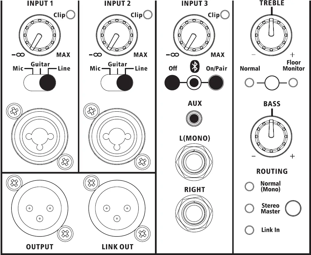
V2308/V2310 BACK PANEL
- CHANNEL 1 AND 2 KNOBSThese knobs set the volume for the inputs below them
- CLIP LEDSIf a Clip LED lights, turn down that input knob, to avoid distorted sound
- MIC/GUITAR/LINE SWITCHESSet these to match the type of source connected to the input below them
- Mic: for microphones, or line level sources with low output volumes
- Guitar: for acoustic guitar or guitar pedal board
- Line: for line level sources
- CHANNEL 1 AND 2 INPUT JACKSConnect XLR or 1/4-inch cables
- CHANNEL 3 KNOBSets the volume for all the inputs below, including Bluetooth® audio, aux and line inputs
- Bluetooth® AUDIO INPUTPress the On/Pair button to enable Bluetooth® and initiate pairing mode
- To pair, look for V2308 or V2310 from your Bluetooth® audio source device.
- LED is lit solid when currently paired, blinking when available for pairing, and off if Bluetooth® has been disabled by a press of the Bluetooth® Off button.
- On/Pair button forces any currently connected Bluetooth® audio source to disconnect, and makes the speaker available for pairing.
- Off button disables Bluetooth®. (Bluetooth® will be re-enabled if you press the On/Pair button.)
- AUX INPUTThis input accepts a stereo or mono unbalanced audio input
- BALANCED LINE INPUTSBalanced or unbalanced line level sources can be connected here
- BASS AND TREBLE KNOBSAdjust the sound of your speaker
- NORMAL / FLOOR MONITOR TUNINGPressing the button selects from the two tunings:
- Normal: for general use including music playback
- Floor Monitor: for enhanced clarity and reduced feedback potential for floor monitors, also may be helpful to avoid excessive bass from wall mounted speakers

- ROUTING
- Normal (Mono): This speaker will output mono audio
- Stereo Master: This speaker will operate as the master (left) speaker of a Smart Stereo pair. Use a mic cable to connect this speaker’s LINK OUT to the INPUT 1 jack of a second speaker of the same type. All inputs should be connected to the first master speaker, which will also set the volume and tone of both speakers.
- Link In: Use this setting for the second speaker of a Smart Stereo pair. The audio from INPUT 1 will be routed directly to the power amp and speaker, with all other inputs and controls being ignored. This can also be used to accept mono audio from a previous speaker, with that previous speaker determining volume and tone.
- OUTPUT JACKOutputs mono audio that is unaffected by TREBLE, BASS, and Normal/Floor Monitor tuning
- LINK OUT JACK
- When ROUTING is set to Smart Stereo, this jack outputs right only audio to feed a second (right) speaker
- When ROUTING is set to Normal (Mono), this jack outputs mono audio to feed a second speaker
- Switches the power on and off
- If the speaker will not power on and you suspect its fuse may have blown, turn off the power switch, and open the fuse compartment using a small flat blade screwdriver. If metal strip in fuse is broken, replace with T4AL 250V fuse (for 100-120 volt use), or T2AL/250V fuse (for 220-240 volt use).
- Connect power cable here.
- Configures speaker for your territory’s voltage. 100-120V is the standard in the USA
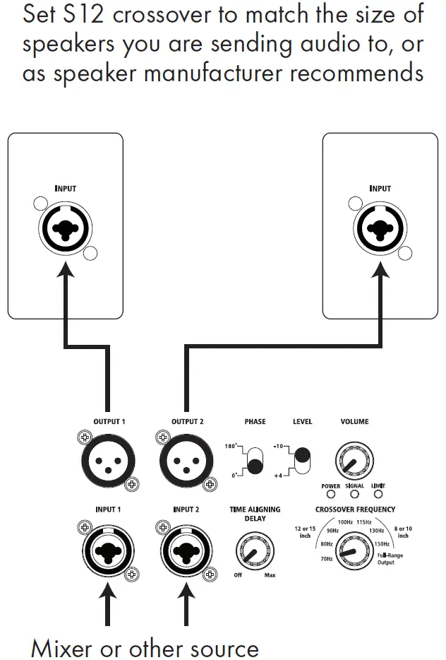
S12 QUICK START GUIDE
SETTING UP / HELPFUL TIPS
- Position the S12 in the desired location, and ensure the speaker is stable.
- Make sure the Power Switch is off.
- Make certain VOLUME knob is turned down.
MAKING THE CONNECTIONS
- Plug connections to Input 1 and 2 from Outputs of signal source.
- See illustrations of common setups below.
- See facing page information regarding Level switch.
CROSSOVER FREQUENCY
- Turn the knob to select a frequency for the crossover.
- Recommended settings for common sizes of speakers are indicated.
PHASE/LEVEL
- For initial use, Phase should be set to 0.
- For initial use, Level should be set to -10.
POWERING UP
- Turn on the power to any devices plugged into Input 1 or Input 2.
- Power ON the S12.
- Slowly turn the VOLUME knob to 12 o’clock.
- Slowly turn up the source volume to the desired level.
SIGNAL/LIMIT/LEVEL
- The SIGNAL LED will light green when input audio is detected.
- If the limiter is triggered, the LIMIT LED will turn RED, indicating the VOLUME knob should be turned down to avoid distorted sound.
- If the LIMIT LED comes on when the VOLUME knob is already at a low level, try setting the LEVEL switch to +4, and see information regarding LEVEL switch on facing page.
PHASE/TIME ALIGNING DELAY
- Set up your system, and play audio through the system to evaluate the low frequency response.
- Try PHASE set to 0, then 180, and leave the switch on the setting that provides more low frequency impact.
- Turn TIME ALIGNING DELAY knob until the maximum sub bass is heard.
LINKING MULTIPLE SUBWOOFERS
- If linking multiple subwoofers, plug the OUTPUT connection(s) of the first subwoofer to the INPUT connection(s) of second subwoofer, and continue the daisy chain to the next speaker.
- Switch Output Crossover Off.
- Turn the Power On in the order of the audio signal to prevent unwanted “pops”. First On / Last Off.
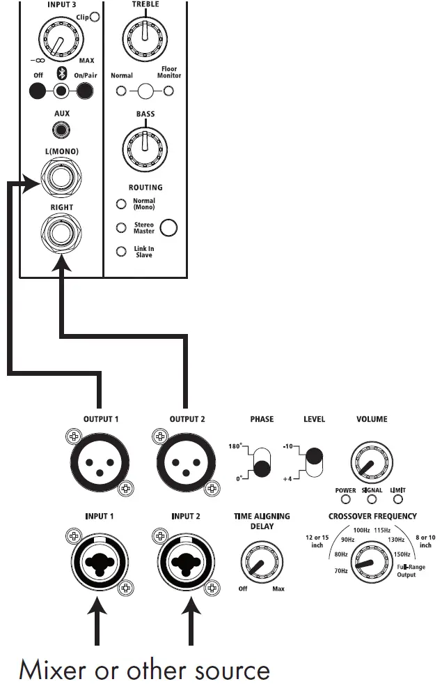
HOOK UP DIAGRAMS
S12 in-Line with Audio Source
Feed-Through from Main Speakers
Feeding Harbinger Smart Stereo Speakers Such as V2308 or V2310
S12 BACK PANEL
- INPUTS 1 AND 2These combo inputs are designed for either TRS or XLR balanced plugs at line level, either from a mixer or another speaker. The source can be either mono or stereo.
- OUTPUTS 1 AND 2These outputs feed through the signal(s) received from the input(s). If the crossover is not set to Full-Range Output, the output signal(s) willbe altered by the crossover, which removes audio below the selected frequency, to allow your speakers that are fed by the sub to focus all their energy and fidelity on reproducing signals above the selected frequency.
- LEVEL SWITCHSet this switch to match the output level of your source:
- Use +4 when your source operates at +4dBu
- Use -10 when your source operates at -10dBVIf you notice that the rear panel LIMIT LED or front panel LED is easily or frequently lit red, even when you have the LEVEL knob turned to a low setting, set this switch to +4 rather than -10.
- CROSSOVERThis knob controls the high precision DSP crossover. Select a value between 70 and 150Hz to have the audio below the selected frequency filtered out of the output signals. Select Full-Range Output to disable the crossover, and output the same full range audio received at the outputs. The audio sent to the internal power amp and speaker will also be filtered, so the subwoofer’s speaker produces only audio below the crossover frequency. When Full-Range Output is chosen, the subwoofer’s speaker limits its top frequency range to 150Hz.
- PHASEThis switch lets you “flip” (reverse) the phase on the power amp 180 degrees when needed to match the polarity of speakers that may operate with opposite polarity to the V2318S, or to account for a phase difference due to the physical distance between the sub and the full range speakers it is operating with. When set to 0, phase is unaffected. When set to 180, the phase of the power amp and internal speaker will be reversed. Once you get your S12 operating as part of your full setup with your full-range speakers, try both settings of this switch, and leave the switch on the setting that provides the most low frequency impact.
- TIME ALIGNING DELAYAfter you’ve set up your system including the S12 subwoofer and your full-range speakers, and are playing audio through the system to evaluate the low frequency response, set the PHASE switch for maximum low frequency impact, and then turn this knob until maximum sub bass is heard.
- VOLUME KNOBSets volume of internal speaker.
- LEDS
- POWER: this LED and front LED will light white when power is on.
- SIGNAL: this LED lights green when audio input is detected.
- LIMIT: this LED and front LED light red when limiter is activated dueto very high level audio input, indicating the VOLUME knob should be turned down to avoid distorted sound. If the LIMIT LED comes on when the VOLUME knob is already at a low level, try setting the LEVEL switch to +4.
- IEC POWER INPUTPlug in the IEC AC power cable here.
- VOLTAGE SELECTORConfigures S12 for your territory’s voltage. 100-120V is the standard in the USA.
- FUSE CARRIERIf the speaker will not power on and you suspect its fuse may have blown, turn off the power switch, and open the fuse compartment using a small flat blade screwdriver. If metal strip in fuse is broken, replace with T6.3AL 250V fuse for 100-120 volt operation, or T3.15AL 250V for 220-240 volt operation.
- POWER SWITCHTurns the VARI subwoofer on or off.
V2308/V2310 SPECIFICATIONS
|
HARBINGER VARI Series |
V2308 |
V2310 |
|
| Amplifier |
DSP |
Selectable Tuning (Normal, Floor Monitor) and Bass and Treble knobs all control the internal DSP to customize the sound | Selectable Tuning (Normal, Floor Monitor) and Bass and Treble knobs all control the internal DSP to customize the sound |
|
Limiter |
Transparent, dynamic DSP limiter for ideal sound quality and system protection at maximum volume | Transparent, dynamic DSP limiter for ideal sound quality and system protection at maximum volume | |
|
Smart Stereo |
A pair of speakers can be connected for unified volume and tone control from the first master speaker, with optimal distribution of mono and audio signals between both speakers | A pair of speakers can be connected for unified volume and tone control from the first master speaker, with optimal distribution of mono and audio signals between both speakers | |
|
Input 1 |
XLR and 1/4-inch TRS balanced/unbalanced compatible audio input with Mic/Guitar/Line Switch and Input Gain Control | XLR and 1/4-inch TRS balanced/unbalanced compatible audio input with Mic/Guitar/Line Switch and Input Gain Control | |
|
Input 2 |
XLR and 1/4-inch TRS balanced/unbalanced compatible audio input with Mic/Guitar/Line Switch and Input Gain Control | XLR and 1/4-inch TRS balanced/unbalanced compatible audio input with Mic/Guitar/Line Switch and Input Gain Control | |
|
Input 3 |
Stereo Line: Left/mono and right 1/4-inch TRS balanced/ unbalanced compatible audio line inputs
Aux: 1/8-inch mini TRS unbalanced input (-10dB) Bluetooth® Audio: with On/Pair and Off buttons plus LED |
Stereo Line: Left/mono and right 1/4-inch TRS balanced/unbalanced compatible audio line inputs Aux: 1/8-inch mini TRS unbalanced input (-10dB) Bluetooth® Audio: with On/Pair and Off buttons plus LED | |
|
Link In |
XLR balanced +4dBv audio input | XLR balanced +4dBv audio input | |
|
Output Jack |
XLR balanced +4dBv audio output | XLR balanced +4dBv audio output | |
|
Power Output |
400 Watts Peak, 100 Watts RMS | 400 Watts Peak, 100 Watts RMS | |
|
Bass EQ Knob |
+/-12dB Shelf, 65Hz | +/-12dB Shelf, 65Hz | |
|
Treble EQ Knob |
+/-12dB Shelf at 6.5kHz | +/-12dB Shelf at 6.5kHz | |
|
Volume |
volume control per channel | volume control per channel | |
|
Power Input |
110-120V, 220-240V, 50-60Hz, 100w power draw | 110-120V, 220-240V, 50-60Hz, 100w power draw | |
|
Other Features |
Removable AC Power Cord | Removable AC Power Cord | |
| Front LED indicates power (white) and limiter (red), rear LEDs indicate clipping (red) per input | Front LED indicates power (white) and limiter (red), rear LEDs indicate clipping (red) per input | ||
| Speaker |
Type |
8″ 2-way vented design | 10″ 2-way vented design |
|
Frequency Response |
65-20K Hz | 55-20K Hz | |
|
Max |
118dB | 120dB | |
|
HF Driver |
Compression Driver, 8 Ohm | Compression Driver, 8 Ohm | |
|
LF Driver |
8˝ Driver, 4 Ohm | 10˝ Driver, 4 Ohm | |
|
Cabinet |
Polypropylene, with rubber surfaced feet | Polypropylene, with rubber surfaced feet | |
|
Grille |
1.2mm steel | 1.2mm steel | |
|
Suspension Points |
V2308 Is Not Designed For Suspension | V2310 Is Not Designed For Suspension | |
|
Pole Mount |
35mm stand pole with M6 screw | 35mm stand pole with M6 screw | |
| Dimensions and Weights |
Product Dimensions |
D: 10.1″ x W: 10.25″ x H: 17.25″ | D: 11.45″ x W: 11.8″ x H: 20″ |
|
Packaging Size |
D: 13.4″ x W: 13.4″ x H: 20.1″ | D: 15″ x W: 15″ x H: 22.85″ | |
|
Net Weight |
15.5 pounds | 20 pounds | |
|
Gross Weight |
19 pounds | 24 pounds |
S12 SPECIFICATIONS
|
HARBINGER VARI Series |
V2318S |
|
| Amplifier |
Inputs |
2 XLR / TRS LINE input |
|
Outputs |
2 XLR line output | |
|
Power Output |
400 watts RMS @ 8 Ohms / 1000 watts Peak | |
|
Volume |
Main volume control | |
|
Power Input |
110-120V, 220-240V, 50-60Hz, 350w power draw | |
|
Other Features |
Class D+ switching power design | |
| Front LED indicates power (white) and limiter (red) | ||
| Rear panel power (white), signal (green), and limiter (red) LEDs | ||
| High precision digital crossover, adjustable from 70-150Hz, or full-range output | ||
| Time Aligning Delay, to easily optimize bass response in any setup | ||
| Phase switch, select 0 or 180 degrees | ||
| Transparent, dynamic DSP limiter | ||
| Speaker |
Type |
Active vented subwoofer |
|
Frequency Response |
35-150Hz | |
|
Max Output |
130dB | |
|
Impedance |
8 Ohm | |
|
Woofer |
12″ subwoofer | |
|
Cabinet |
Plywood with black Polyurea painted finish | |
|
Grille |
1.5mm aluminum | |
|
Pole |
35mm stand pole | |
|
Features |
Rubber feet | |
|
Dimensions and Weights |
Unit Size |
D: 18.1″ x W: 14.6″ x H: 17.2″ (including feet) |
|
Package Size |
D: 21.7″ x W: 18.1″ x H: 20.1″ | |
|
Unit Weight |
46.2 pounds | |
|
Package Weight |
52.8 pounds |
IMPORTANT SAFETY INSTRUCTIONS
Please keep this instruction manual for future reference and for the duration of owning the Harbinger powered loudspeaker or subwoofer. Please carefully read and understand the instructions inside this owner’s manual before attempting to operate your new powered loudspeaker.This instruction manual includes essential safety information regarding the use and maintenance of the amplifier. Take special care to heed all warning symbols and signs inside this manual and those printed on the amplifier on the back of the loudspeaker.
WARNINGTO PREVENT FIRE OR SHOCK HAZARD, DO NOT EXPOSE THE AMPLIFIER TO WATER/MOISTURE, NOR SHOULD YOU OPERATE THE AMPLIFIER NEAR ANY WATER SOURCE.The exclamation point triangular symbol is intended to alert the user to the presence of important operating and maintenance(servicing) instructions in the user manual accompanying the Amplifier.The lightning flash with an arrow triangular symbol is intended to alert the user to the presence of non-insulated “dangerous voltage” within the product’s enclosure, and may be of sufficient magnitude to constitute a risk of electric shock.
WARNINGHandle the power supply cord with care.Do not damage or deform it as it may cause electric shock or malfunction when used. Hold the plug attachment when removing from wall outlet. Do not pull on the power cord.
IMPORTANT SAFETY PRECAUTIONS
- Read these instructions.
- Keep these instructions.
- Heed all warnings.
- Follow all Instructions.
- Do not use this apparatus near water.
- Clean only with dry cloth.
- Do not block any ventilation openings. Install in accordance with the manufacturer’s instructions. DO NOT turn on the VARI amplifier module before connecting all other external devices.
- Do not install near any heat sources such as radiators, heat registers, stoves, or other apparatus (including amplifiers) that produce heat.
- Do not defeat the safety purpose of the polarized or grounding-type plug. A polarized plug has two blades with one wider than the other. A grounding type plug has two blades and a third grounding prong. The wide blade or the third prong is provided for your safety. If the provided plug does not fit into your outlet, consult an electrician for replacement of the obsolete outlet.
- Protect the power cord from being walked on or pinched particularly at plugs, convenience receptacles, and the point where they exit from the apparatus.
- Only use attachment/accessories specified by the manufacturer.
- Use only the cart, stand, tripod, bracket or table specified by the manufacturer, or sold with the apparatus. When a cart is used, use caution when moving the cart/ apparatus combination to avoid injury from tip-over.
- Unplug this apparatus during lightning storms or when unused for long periods of time.
- Refer all servicing to qualified service personnel. Servicing is required when the apparatus has been damaged in any way, such as power-supply cord or plug is damaged, liquid has been spilled or objects have fallen into the apparatus, the apparatus has been exposed to rain or moisture, does not operate normally, or has been dropped.
- POWER SOURCES – This product should be operated only from the type of power source indicated on the rating label. If you are not sure of the type of power supply to your home, consult your product dealer or local power company.
- WALL OR CEILING MOUNTING – The product should never be mounted to a wall or ceiling.
- Where the mains plug or an appliance coupler is used as the disconnect device, the disconnect device shall remain readily operable.
- OBJECT AND LIQUID ENTRY – Care should be taken so that objects do not fall and liquids are not spilled into the enclosure through openings.
- Water and Moisture: This product should be kept away from direct contact with liquids. The apparatus shall not be exposed to dripping or splashing and that no objects filled with liquids, such as vases, shall be placed on the apparatus.
- Keep the speaker system out of extended or intense direct sun light.
- No containers filled with any type of liquid should be placed on or near the speaker system.
- SERVICING – The user should not attempt any service to the speaker and/or amplifier beyond that described in the operating instructions. All other servicing should be referred to qualified service personnel.
- VENTILATION – Slots and openings in the amplifier are provided for ventilation and to ensure reliable operation of the product and to protect it from overheating. These openings must not be blocked or covered. The openings should never be blocked by placing the product on a bed, sofa, rug, or other similar surface. This product should not be placed in a built-in installation such as a bookcase or rack.
- Protective earthing terminal: The apparatus should be connected to a main socket outlet with a protective earthing connection.
- ACCESSORIES – Do not place this product on an unstable cart, stand, tripod, bracket, or table. The product may fall, causing serious injury to a child or adult, and serious damage to the product. Use only with a cart, stand, tripod, bracket, or table recommended by the manufacturer, or sold with the product.
- When moving or not using the appliance, secure the power cord (e.g., wrap it with a cable tie). Be careful not to damage the power cord. Before using it again, make sure the power cord has not been damaged. If the power cord has been damaged at all, bring the unit and cord to a qualified service technician for repair or replacement as specified by the manufacturer.
- LIGHTNING – For added protection during a lightning storm, or when it is left unattended and unused for long periods of time, unplug it from the wall outlet. This will prevent damage to the product due to lightning and power-line surges.
- REPLACEMENT PARTS – When replacement parts are required, be sure the service technician has used replacement parts specified by the manufacturer or have the same characteristics as the original part. Unauthorized substitutions may result in fire, electric shock, or other hazards.
WARRANTY/CUSTOMER SUPPORT
2 YEAR HARBINGER LIMITED WARRANTYHarbinger provides, to the original purchaser, a two (2) year limited warranty on materials and workmanship on all Harbinger cabinets, loudspeaker and amplifier components from the date of purchase.For warranty support, please visit our website at www.HarbingerProAudio.com, or contact our Support Team at 888-286-1809 for assistance. Harbinger will repair or replace the unit at Harbinger’s discretion.This warranty does not cover service or parts to repair damage caused by neglect, abuse, normal wear and tear and cosmetic appearance to the cabinetry not directly attributed to defects in materials or workmanship. Also excluded from coverage are damages caused directly or indirectly due to any service, repair(s), or modifications of the cabinet, which has not been authorized or approved by Harbinger. This two (2) year warranty does not cover service or parts to repair damage caused by accident, disaster, misuse, abuse, burnt voice-coils, over-powering, negligence, inadequate packing or inadequate shipping procedures.The sole and exclusive remedy of the foregoing limited warranty shall be limited to the repair or replacement of any defective or non-conforming component. All warranties including, but not limited to, the express warranty and the implied warranties of merchantability and fitness for a particular purpose are limited to the two (2) year warranty period. Some states do not allow limitation on how long an implied warranty lasts, so the above limitation may not apply to you. There are no express warranties beyond those stated here. In the event that applicable law does not allow the limitation of the duration of the implied warranties to the warranty period, then the duration of the implied warranties shall be limited to as long as is provided by applicable law. No warranties apply after that period.
Retailer and manufacturer shall not be liable for damages based upon inconvenience, loss of use of product, loss of time, interrupted operation or commercial loss or any other incidental or consequential damages including but not limited to lost profits, downtime, goodwill, damage to or replacement of equipment and property, and any costs of recovering, reprogramming, or reproducing any program or data stored in equipment that is used with Harbinger products. This guarantee gives you specific legal rights; you may have other legal rights, which vary from state to state.HarbingerP.O. Box 5111, Thousand Oaks, CA 91359-5111All trademarks and registered trademarks mentioned herein are recognized as the property of their respective holders.2101-20441853
report this ad![]()
References
[xyz-ips snippet=”download-snippet”]