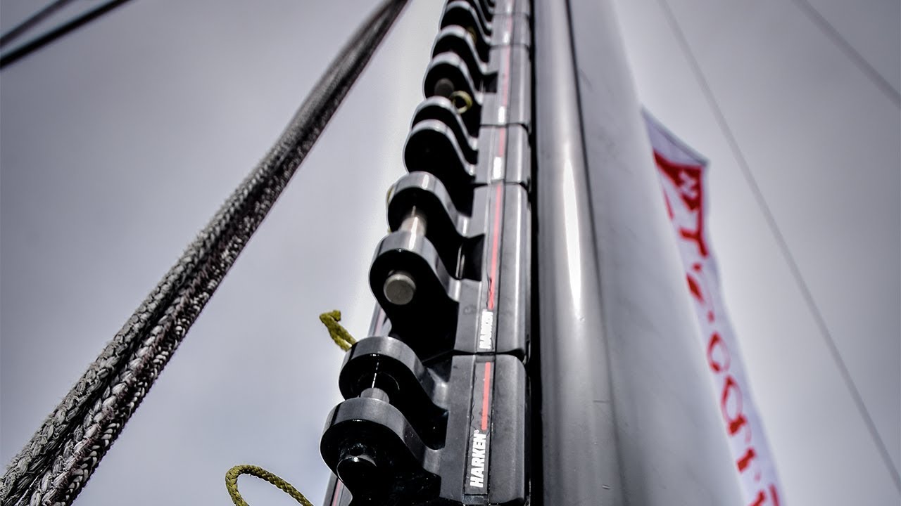
HARKEN Battcar
Introduction
This manual gives technical information on installation and service. This information is destined exclusively for specialized personnel or expert users. Installation, disassembling, and reassembling by personnel who are not experts may cause serious damage to property or injury to users and those in the vicinity of the product. If you do not understand an instruction contact Harken. The user must have appropriate training in order to use this product.Harken accepts no responsibility for damage or harm caused by not observing the safety requirements and instructions in this manual. See limited warranty, general warnings, and instructions in www.harken.com/manuals.
PurposeHarken Battcars are designed to reduce the size of or completely drop the mainsail on a sailboat so wind has little effect on the sail. Use of this product for other than normal sailboat applications is not covered by the limited warranty.
Safety Precautions
WARNING! This symbol alerts you to potential hazards that may kill or hurt you and others if you don’t follow instructions. The message will tell you how to reduce the chance of injury.
CAUTION! This symbol alerts you to potential hazards that may hurt you and others if you do not follow instructions. The message will tell you how to reduce the chance of injury.
WARNING! Strictly follow all instructions to avoid potential hazards that may kill or hurt you and others. See www.harken.com/manuals for general warnings and instructions.
Preassembly – CB System (Slug Mount/Drill & Tap)
Cars
Part No Description Comments
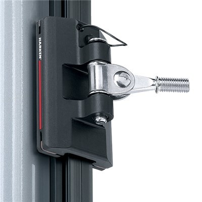
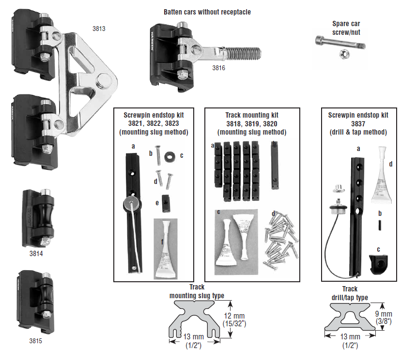
3813 Headboard car3814 Slider intermediate car If battens are close enough intermediate cars are not needed.3815 CB intermediate car If battens are close enough intermediate cars are not needed.3816 Batten car 10 mm Threaded stud. Purchase batten receptacle separately.
Track and Accessories
Part No. Description Includes
Mounting slug method
3818, 3819 Track Mounting Kit (a) 19 x mounting slugs 19 mm (3/4″); (b) 1 x connector slug 67 mm (2 5/8″); (c) 2 x tubes blue Loctite®3820 (d) 21 x HFS1009 flathead screws 4 x 20 mm.3821, 3822 Screwpin Endstop Kit (a) 1 x 152 mm (6″) end track with screwpin stop; (b) 1 x flathead screw HFS948 4 x 25 mm; (c) 1 x topstop; (d) 2 x HFS1009 flathead screws 4 x 20 mm; (e) 1 x mounting slug 19 mm 3823 (3/4″); (f) 1 x tube blue Loctite®.
3817 Track Section length: 2.05 m (6’8 7/8″). Number track sections vary according to luff length of mainsail.
Drill & tap method
3837 Screwpin Endstop Kit (a) 1 x 152 mm (6″) end track with screwpin stop; (b) 1 x 2711 splice link; (c) 1 x H-28411C endstop (d) 1 x tube blue Loctite®
2707 Track (Micro CB) Use for masts without grooves or when slugs will not fit. Purchase stainless steel 4 mm (#8) screws separately.Do not use 3817 open-backed track. It requires mounting slugs. See page 11 for drill/tap sizes and mounting instructions
Tools/Sizing/Sail Modifications/Track Length
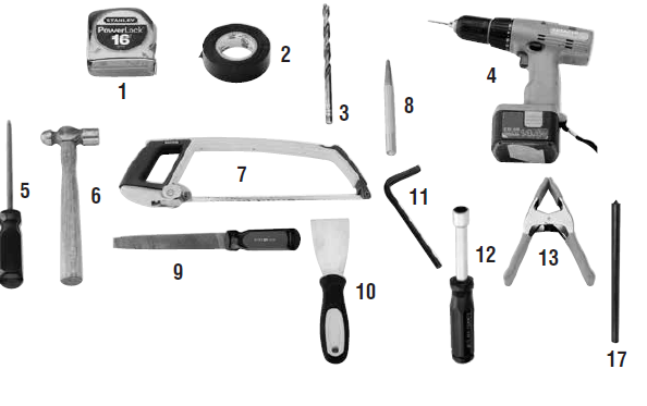
Tools you will need
- Tape measure
- Tape
- Power drill (screwdriver)
- Drill bit 3/16″ (4.5 mm) Drill & tap (additional)
- Phillips screwdriver
- Hammer
- Hacksaw
- Center punch
- File 17. Transfer punch
- Putty knife
- Hex wrench (4 mm)
- Nut driver (8 mm) or open wrench
- Spring clamp
- Spring-loaded centerpunch (not shown)
- Drill bit 1/8″ (3 mm) (not shown)
- Tap 8-32 (M4) (not shown)
Mast-up installation: Stepladder secured to the boat.Work height: 7′ (2.13 m) above boom
Sizing
Make sure that you have the correct size battcar system for your boat.
Maximum Sail Area Part No. Part No. Part No. Monohull Multihull Headboard Battcars Intermediate Car300 ft2 28 m2 250 ft2 23 m2 3813 3816 3814, 3815
Sail Modifications
- Mainsail Headboard
- Drill new halyard location
- Drill Attachment to accept clevis pin for 3813 headboard car coupler.
- Batten receptacle on sail to accept 10 mm threaded stud.Note: Harken does not supply receptacle.
- Becket spacer on sail for 3815 intermediate car, or install 3814 slider on sail.
Determine Track Length
Note: Track length is longer than sail luff length.
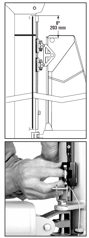
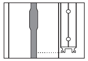
- Upper End:Extend track 8″ (203 mm) above headboard halyard attachment point to allow for sail stretch as sail ages. Track must not block mast halyard exit.
- Lower End:Place 6″ (152 mm) Screwpin Endstop track on mast. Make sure car clears gooseneck fittings and adjust height as necessary. Measure to lower end of track.
Number of 3817 Track Sections (Slug Mount)
Variable length top track included
Track length Number of 2.05 m (6’8 7/8″) track sections
6.350 m to 8.382 m20’10” to 27’6″8.407 m to 10.439 m27’7″ to 34’3″ 510.465 m to 12.471 m34’4″ to 40’11” 612.497 m to 14.529 m41’0″ to 47’8″ 7
Pre-Assembly (Slug Mount)
Round track length to nearest 1″ (25 mm).Note: Chart is based on using 3817 track–length 2.05m (6’8 7/8″) and 3821, 3822, or 3823 Endstop Kits–length 152.4 mm (6″).
| Total track length (as defined on page 3) | Top track length | ||||||||
| 20’10” | 6.350 m | 27′ 7″ | 8.407 m | 41′ 0″ | 12.497 m | 13/16″ | 30 mm | ||
| 20’11” | 6.375 m | 27′ 8″ | 8.433 m | 34′ 4″ | 10.465 m | 41′ 1″ | 12.522 m | 2″ | 51 mm |
| 21′ 0″ | 6.401 m | 27′ 9″ | 8.458 m | 34′ 5″ | 10.490 m | 41′ 2″ | 12.548 m | 3″ | 76 mm |
| 21′ 2″ | 6.452 m | 27’11” | 8.509 m | 34′ 7″ | 10.541 m | 41′ 4″ | 12.598 m | 5″ | 127 mm |
| 21′ 4″ | 6.502 m | 28′ 1″ | 8.560 m | 34′ 9″ | 10.592 m | 41′ 6″ | 12.649 m | 7″ | 178 mm |
| 21′ 6″ | 6.553 m | 28′ 3″ | 8.611 m | 34’11” | 10.643 m | 41′ 8″ | 12.700 m | 9″ | 229 mm |
| 21′ 8″ | 6.604 m | 28′ 5″ | 8.661 m | 35′ 1″ | 10.693 m | 41’10” | 12.751 m | 11″ | 279 mm |
| 21’10” | 6.655 m | 28′ 7″ | 8.712 m | 35′ 3″ | 10.744 m | 42′ 0″ | 12.802 m | 1′ 1″ | 330 mm |
| 22′ 0″ | 6.706 m | 28′ 9″ | 8.763 m | 35′ 5″ | 10.795 m | 42′ 2″ | 12.852 m | 1′ 3″ | 381 mm |
| 22′ 2″ | 6.756 m | 28’11” | 8.814 m | 35′ 7″ | 10.846 m | 42′ 4″ | 12.903 m | 1′ 5″ | 432 mm |
| 22′ 4″ | 6.807 m | 29′ 1″ | 8.865 m | 35′ 9″ | 10.897 m | 42′ 6″ | 12.954 m | 1′ 7″ | 483 mm |
| 22′ 6″ | 6.858 m | 29′ 3″ | 8.915 m | 35’11” | 10.947 m | 42′ 8″ | 13.005 m | 1′ 9″ | 533 mm |
| 22′ 8″ | 6.909 m | 29′ 5″ | 8.966 m | 36′ 1″ | 10.998 m | 42’10” | 13.056 m | 1’11” | 584 mm |
| 22’10” | 6.960 m | 29′ 7″ | 9.017 m | 36′ 3″ | 11.049 m | 43′ 0″ | 13.106 m | 2′ 1″ | 635 mm |
| 23′ 0″ | 7.010 m | 29′ 9″ | 9.068 m | 36′ 5″ | 11.100 m | 43′ 2″ | 13.157 m | 2′ 3″ | 686 mm |
| 23′ 2″ | 7.061 m | 29’11” | 9.119 m | 36′ 7″ | 11.151 m | 43′ 4″ | 13.208 m | 2′ 5″ | 737 mm |
| 23′ 4″ | 7.112 m | 30′ 1″ | 9.169 m | 36′ 9″ | 11.201 m | 43′ 6″ | 13.259 m | 2′ 7″ | 787 mm |
| 23′ 6″ | 7.163 m | 30′ 3″ | 9.220 m | 36’11” | 11.252 m | 43′ 8″ | 13.310 m | 2′ 9″ | 838 mm |
| 23′ 8″ | 7.214 m | 30′ 5″ | 9.271 m | 37′ 1″ | 11.303 m | 43’10” | 13.360 m | 2’11” | 889 mm |
| 23’10” | 7.264 m | 30′ 7″ | 9.322 m | 37′ 3″ | 11.354 m | 44′ 0″ | 13.411 m | 3′ 1″ | 940 mm |
| 24′ 0″ | 7.315 m | 30′ 9″ | 9.373 m | 37′ 5″ | 11.405 m | 44′ 2″ | 13.462 m | 3′ 3″ | 991 mm |
| 24′ 2″ | 7.366 m | 30’11” | 9.423 m | 37′ 7″ | 11.455 m | 44′ 4″ | 13.513 m | 3′ 5″ | 1.041 m |
| 24′ 4″ | 7.417 m | 31′ 1″ | 9.474 m | 37′ 9″ | 11.506 m | 44′ 6″ | 13.564 m | 3′ 7″ | 1.092 m |
| 24′ 6″ | 7.468 m | 31′ 3″ | 9.525 m | 37’11” | 11.557 m | 44′ 8″ | 13.614 m | 3′ 9″ | 1.143 m |
| 24′ 8″ | 7.518 m | 31′ 5″ | 9.576 m | 38′ 1″ | 11.608 m | 44’10” | 13.665 m | 3’11” | 1.194 m |
| 24’10” | 7.569 m | 31′ 7″ | 9.627 m | 38′ 3″ | 11.659 m | 45′ 0″ | 13.716 m | 4′ 1″ | 1.245 m |
| 25′ 0″ | 7.620 m | 31′ 9″ | 9.677 m | 38′ 5″ | 11.709 m | 45′ 2″ | 13.767 m | 4′ 3″ | 1.295 m |
| 25′ 2″ | 7.671 m | 31’11” | 9.728 m | 38′ 7″ | 11.760 m | 45′ 4″ | 13.818 m | 4′ 5″ | 1.346 m |
| 25’4″ | 7.722 m | 32′ 1″ | 9.779 m | 38′ 9″ | 11.811 m | 45′ 6″ | 13.868 m | 4′ 7″ | 1.397 m |
| 25′ 6″ | 7.772 m | 32′ 3″ | 9.830 m | 38’11” | 11.862 m | 45′ 8″ | 13.919 m | 4′ 9″ | 1.448 m |
| 25′ 8″ | 7.823 m | 32′ 5″ | 9.881 m | 39′ 1″ | 11.913 m | 45’10” | 13.970 m | 4’11” | 1.499 m |
| 25’10” | 7.874 m | 32′ 7″ | 9.931 m | 39′ 3″ | 11.963 m | 46′ 0″ | 14.021 m | 5′ 1″ | 1.549 m |
| 26′ 0″ | 7.925 m | 32′ 9″ | 9.982 m | 39′ 5″ | 12.014 m | 46′ 2″ | 14.072 m | 5′ 3″ | 1.600 m |
| 26′ 2″ | 7.976 m | 32’11” | 10.033 m | 39′ 7″ | 12.065 m | 46′ 4″ | 14.122 m | 5′ 5″ | 1.651 m |
| 26′ 4″ | 8.026 m | 33′ 1″ | 10.084 m | 39′ 9″ | 12.116 m | 46′ 6″ | 14.173 m | 5′ 7″ | 1.702 m |
| 26′ 6″ | 8.077 m | 33′ 3″ | 10.135 m | 39’11” | 12.167 m | 46′ 8″ | 14.224 m | 5′ 9″ | 1.753 m |
| 26′ 8″ | 8.128 m | 33′ 5″ | 10.185 m | 40′ 1″ | 12.217 m | 46’10” | 14.275 m | 5’11” | 1.803 m |
| 26’10” | 8.179 m | 33′ 7″ | 10.236 m | 40′ 3″ | 12.268 m | 47′ 0″ | 14.326 m | 6′ 1″ | 1.854 m |
| 27′ 0″ | 8.230 m | 33′ 9″ | 10.287 m | 40′ 5″ | 12.319 m | 47′ 2″ | 14.376 m | 6′ 3″ | 1.905 m |
| 27′ 2″ | 8.280 m | 33’11” | 10.338 m | 40′ 7″ | 12.370 m | 47′ 4″ | 14.427 m | 6′ 5″ | 1.956 m |
| 27′ 4″ | 8.331 m | 34′ 1″ | 10.389 m | 40′ 9″ | 12.421 m | 47′ 6″ | 14.478 m | 6′ 7″ | 2.007 m |
| 27′ 6″ | 8.382 m | 34′ 3″ | 10.439 m | 40’11” | 12.471 m | 47′ 8″ | 14.529 m | 6’8 7/8″ | 2.054 m |
Preassembly – CB System (Slug Mount)
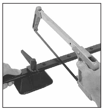
- Cut special length top track from 2.05 m (6’8 3/4″) track.
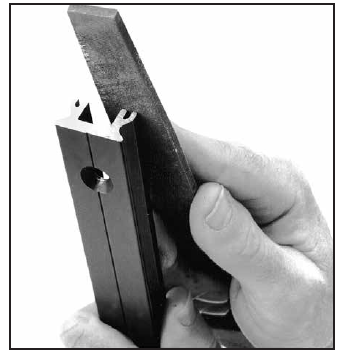
- Deburr cut. Slightly round track corners that will slide against mast
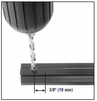
- Drill 4.5 m (3/16″) top stop hole in cut end of track.Use existing hole if top track is 30 mm (1 3/16″).
Check Fit of Mounting Slugs/Cars
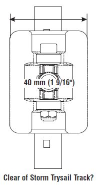
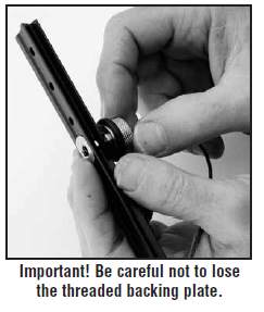
67 mm (2 5/8″) connector slug must fit feeder opening. File opening to make longer. Use halyard with retrieval line to hoist 67 mm (2 5/8″) connector slug up mast to check for burrs in groove.Mast prebend: May require straightening before installation.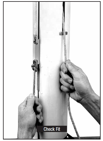 Storm Trysail TrackCar’s 40 mm (1 9/16″) width must clear storm trysail track. Tracks often converge above spreaders. Aft face of mast must be flat or convex.
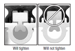
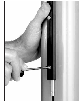
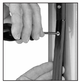
 Test track: Put mounting slug in groove, track section on mast.Tighten with screw. Track must be drawn tightly to mast.Mounting screw must be long enough for mast groove. If necessary, purchase longer screws.
Warning! Screws need minimum 11 threads (turns) engaged to hold track to mast. Turn screw 360° five times after threads engage slug.
Installation – CB System (Slug Mount)
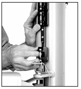
- Slip top track slugs into mast groove. Use 19 mm (3/4″) mounting slug for top stop.Note: If top track is 30 mm (1 3/16″), use 67 mm (2 5/8″) connector slug for top stop. Install 67 mm (2 5/8″) connector slug at bottom.Mast up: Tape 32 mm (1 1/4″) slug even with top of upper track. Tape other slugs in place.
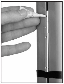
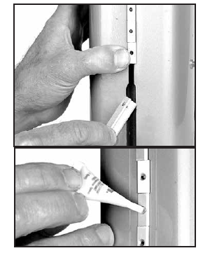
- Squeeze one drop blue Loctite® into each connector slug hole.
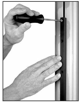
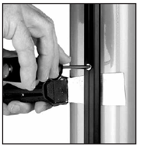
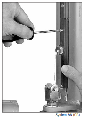
- Thread 4 mm x 25 mm endstop screw through endstop, track, and into endstop slug.Mast up: Remove tape. Tighten screw to hold track.
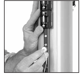
- Slide slugs into place with putty knife. Loosely install 4 mm x 20 mm screws.Tip: Use putty knife to see if screws are loose enough to slide in groove.Remember: Tracks may stick when reaching a spliced area on mast.
- Loosen top screw. Slide top track up and position next 2.05 m (6’8 7/8″) track.Mast up: Tighten bottom screw to hold track.
- Slide 19 mounting slugs and then the connector slug into mast groove.Mast up: Tape in place.One drop blue Loctite® into each hole.
- Hold full-length track piece up to mast. Loosely install top screw. Use putty knife to slide additional slugs and connector slug into place. Loosely install all nineteen 4 mm x 20 mm screws.
- Slide tracks up enough to fit next track.Mast up: Hold upper tracks. Loosen screw that holds tracks. Slide track up. Tighten new bottom screw securely.
- Repeat until full-length tracks installed
- Raise tracks so 152 mm (6″) bottom track fits.
- Install Screwpin Endstop Kit.Note: If bottom full-length track blocks feeder gap, load bottom track slugs before installing track.
 Note: If bottom full-length track blocks feeder gap, load bottom track slugs before installing track.
Preassembly/Installation – CB System (Drill & Tap)
Track and Accessories
Part No. Description Includes
Purchase from Harken
3837 Screwpin endstop kit (a) 1 x 152 mm (6″) end track with screwpin stop; (b) 1 x 2711 splice link;(c) 1 x H-28411C endstop (d) 1 x tube blue Loctite
2707 Track (micro CB) Use for masts without grooves or when slugs will not fit. Purchase stainless steel 4 mm (#8) screws separately. Do not use 3817 open-backed track. It requires mounting slugs. See page 11 for drill/tap sizes and mounting instructions
2711 Splice links One needed for each track joint
Purchase Separately
#8 (4 mm) Flathead screws Purchase 20 fasteners/meter of track
Drill 3 mm (1/8″)Tap 8-32 (M4)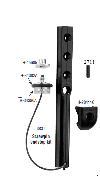
Considerations for Determining Track Length.Note: Track is longer than sail luff length.
- Upper end: Extend track 203 mm (8″) above headboard halyard attachment point to allow for sail stretch as main ages. Track must not block mast halyard exit.
- Lower end: Place 152 mm (6″) Screwpin Endstop track on mast. Make sure car clears gooseneck fittings and adjust height as necessary. Measure to lower end of track.
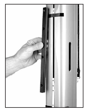
 Remove old trackIMPORTANT! Before removing old track, scribe pencil line down either side
Drill, Tap, and FastenAfter old track is removed, attach string to mast to line up track during installation.
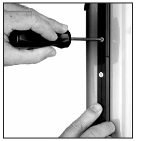
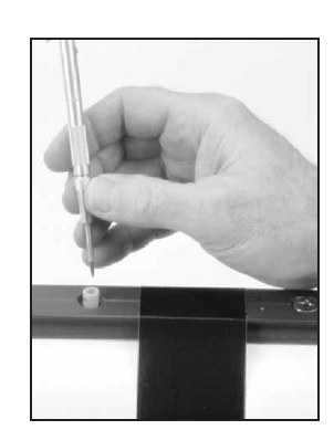
- Start at one end of track and work down: Do not drill and tap from both track ends. Clamp or duct tape track on mast. Center punch in center of track hole.Tip: Use a narrow shaft spring-loaded machinist’s center punch with plastic centering tube or a transfer punch.
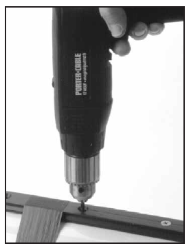
- Drill track hole, holding drill perpendicular to mast face. Tap threads and install screws using blue Loctite®.
- Align track at joints. Use 2711 splice links and round rods or dowels on outside of track to align during installation. Hold in place with spring or “C” clamps until track is secured. Load all cars before installing bottom track and endstop.
Load Cars on Track
IMPORTANT! Keep balls captive by loading cars onto track without sail installed. Car must have 20 balls per side. Consult chart for correct type of balls
DO NOT MIX CARS. High-load brown Torlon® balls are used in headboard and batten cars. Luff cars use low-load black Delrin® balls.
| No. | Car Type | in | mm | Color | Material | per Car | No. | Balls/Set | in | mm |
| 3813 | Headboard Cars | 5 3/16 | 132 | Brown | Torlon® | 40 | 2708 | 20 | 3/16 | 5 |
| 3814 | Slider Intermediate Car | 1 3/4 | 44 | — | — | — | — | — | — | — |
| 3815 | CB Intermediate Car | 2 3/16 | 56 | Black | Delrin® | 40 | HSB240 | 1 | 3/16 | 5 |
| 3816 | Batten Car w/Threaded Stud | 2 3/16 | 56 | Brown | Torlon® | 40 | 2708 | 20 | 3/16 | 5 |
- Headboard cars: Hold car so cap screw head faces up. Align car on guide section of loader track and gently roll onto upper tracks. If car sticks, realign and roll onto track.Tip: To load headboard car assembly, angle headboard coupler, roll car onto track. If necessary, remove headboard assembly
- Load Intermediate car (if used). Alternate with batten cars until all cars are loaded.Mast up: Use halyard to hold cars up.
- Install Screwpin stop.
Operation – CB System (Slug Mount/Drill & Tap)
Load Cars with SailLine up car on guide portion of loader. Press car towards mast and carefully roll car onto track. Begin with upper cars and work down.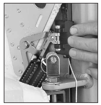
Lost BallsConsult chart for ball type: Torlon® or Delrin®. Place car on edge with retaining clip in place. Insert balls one-by-one from center of clip and roll into return race. Do not overfill car.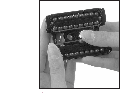
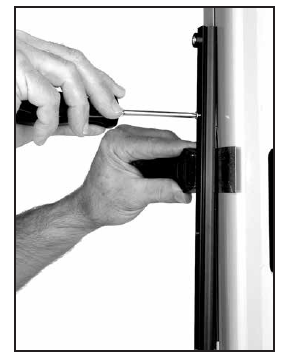
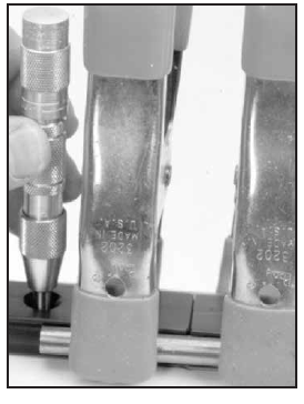
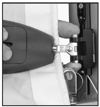
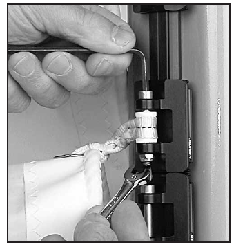
- Beginning with lower cars, use 4 mm hex wrench and 8 mm wrench or nut driver to attach sail to cars. Tighten locknut until bottom tip of fastener is flush with nut.
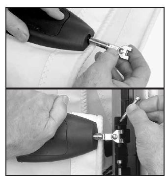
- Screw threaded stud to terminal.
- Load toggle using 4 mm hex wrench and 8 mm wrench or nut driver. Tighten locknut. Do not over tighten
- Attach head of sail to headboard car with clevis pin and cotter pin
 Attach head of sail to headboard car with clevis pin and cotter pin
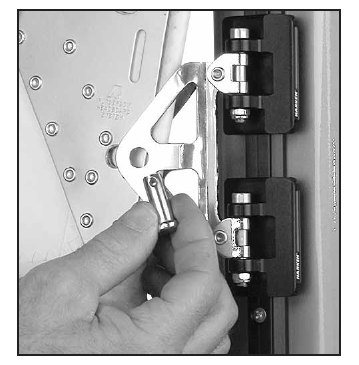
Sail Removal/Lazy Jacks/Operating Precautions
Car Maintenance/CleaningClean beginning of season, or if cars bind. Squirt detergent and water into ball bearings. Circulate by moving cars up and down. Let stand. To remove detergent, spray water into ball bearings and circulate. Clean tracks with detergent and water.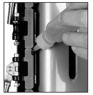 Use OneDrop™ Ball ConditionerOnce dry, use only a single drop of McLube® OneDrop™ ball bearing conditioner. Do not use spray lubricants because ball bearings may skid not roll. Apply one to two drops of McLube® OneDrop™ to ball contact surfaces of track. Roll car back and forth through OneDrop™ several times to distribute onto bearings. Wipe remaining OneDrop™ off track. OneDrop™ is preferred but you can also use one to two drops of alight machine oil. Too much attracts dirt.
InspectInspect Battcars for loose locknuts. Replace. Inspect batten receptacles for loose screws.Removing SailFrom Cars: Remove clevis pin from head of sail. Use a 4 mm hex wrench and a 8 mm wrench or nut driver on other cars.Cars and Sail: Keep cars lined up with track when sliding off.Inspect Cars: 20 balls per side. Replace 5 mm locknut after two removals.
Lazy JacksUse shock cord to hold lazy jacks open so batt cars and battens will not catch on them when hoisting sail. This will also help stop slapping of lazy jacks on sail. Attach one end to lower spreader tips and the other to lazy jacks. Make sure shock cord is long enough so boom can swing out all the way without damaging spreaders.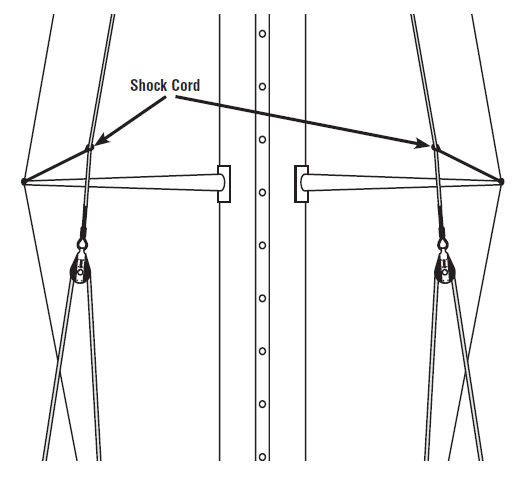 Operating PrecautionsWhen lowering sail, do not let halyard go. Ease cars down by keeping a wrap on winch. On boats with unstayed masts, vang must be used to prevent over rotation of upper part of sail. Over rotation can damage batten receptacles.
Sailmaker’s Instructions – CB System (Slug Mount/Drill & Tap) Dimensions/Installing Headboard Coupler Car
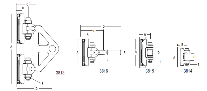 Dimensions
| A | B | C | D | E | F | |||||
| Part No. | in | mm | in | mm | in | mm | in | mm | Locknut Size mm | Stud Size mm |
| 3813 | 53/16 | 132 | 1 | 25 | 113/16 | 46 | 23/4 | 70 | 5 | — |
| 3814 | 13/4 | 44 | 1 | 25 | — | — | 3/4 | 19 | 5 | — |
| 3815 | 23/16 | 56 | 1 | 25 | — | — | 3/4 | 19 | 5 | — |
| 3816* | 23/16 | 561 | 1 | 25 | 13/4 | 45 | 35/16 | 84 | 5 | 10 |
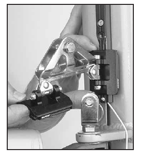
Installing 3813 Headboard Coupler Car Assembly3813 headboard coupler attaches to standard headboards—some headboard modification required.Maximum thickness of headboard plates and sail: 9/16″ (14 mm)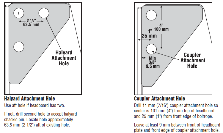
Attachment Points/Reef Points
Distance Between Attachment PointsBattens and intermediate cars placed at sailmaker’s discretion. Maximum distance between attachment points is 1.2 m to 1.35 m (4′ to 4’6″). Distance may be slightly greater. Contact Harken to discuss sail reshaping to eliminate luff flutter.Note: Adding battens may reduce stack height by eliminating luff cars.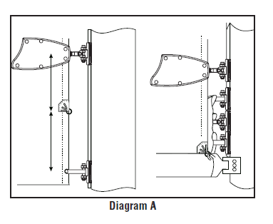
Setting Reef PointsSpace reef points halfway between sail attachment points. Battens or reef points may need to be moved—Diagram A. Note Batten fittings and cars cannot handle reefing outhaul or downhaul loads. Transfer loads to tack fitting—Diagram B.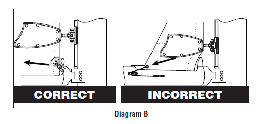
Attaching Sail to Intermediate Cars
Attach Sail to Intermediate CarsSail setback from luff tape to intermediate car clevis pin:3814 – 20 mm (13/16″)3815 – 20 mm (13/16″)Plastic spacers come with 3814 and 3815 intermediate cars. Seize spacer to webbing by stitching just behind plastic spacer. Seize webbing to sail by stitching up against sail.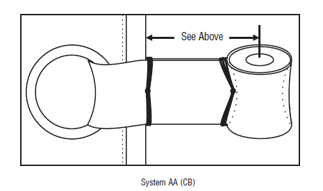
Operation Troubleshooting
| Problem | Probable Cause | Solution |
| Tracks do not butt up against each other | Cut end of top or bottom track is at joint. | Make sure the anodized end is towards the full length track. |
| Track weight pulling tracks apart. | Tracks will come together when you loosen bottom screw and push the tracks up mast. | |
| Mounting slugs do not fit | Slugs wrong size. | Different size slug required. Contact your dealer. |
| Mounting screws will not tighten. | Incorrect mounting slug used. | Different size slug required. Contact your dealer. |
| Track will not slide up mast. | Slugs catching on mast splice. | Loosen screws slightly. If necessary have someone at splice area to wiggle the slug past the splice. |
| Corners of cut track catching. | Use file to round off corners of track. | |
| Mast has too much prebend. | Ease backstay and/or straighten mast. | |
| Paint or other material clogging mast groove. | Clean out groove. | |
| Cars do not fit on track. | Track and cars are not the same size. | Contact your dealer or Harken. |
| Balls are missing. | Remove cars, load balls and slide cars back on track. | |
| Sail headboard does not fit inside coupler. | Ring was not pressed far enough. | Take sail to sailmaker. |
| Problem | Probable Cause | Solution |
| Cars bind. | Balls missing from car. | Remove cars, load balls and slide cars back on track. |
| Dirt in cars. | Use detergent and fresh water to flush dirt out of cars; move cars up/down do circulate; follow with high pressure water; clean track grooves. | |
| Nut on Battcar is not holding. | Locknut has been used too many times. | Get new 5 mm locknut. |
| Batten receptacle does not rotate. | Nuts are too tight. | Loosen nuts slightly. |
| Cars jam when raising sail. | Headboard or cars are catching on lazy jacks. | Use topping lift or rod vang and shock cord to pull lazy jacks out to shrouds. |
| Sail will not go all the way up. | Sail is too tall or sheave is too far forward. | Have sail shortened or move sheave aft. |
| Vertical post or pin on batten receptacle bending. | Reef loads are being transferred to batten receptacle. | Transfer reef downhaul and outhaul loads to mast or boom gooseneck. |
| Reef tack fitting will not reach reef hook. | Reef point too close to sail attachment. | Move intermediate car sail attachment. |
General Maintenance (see specific maintenance on page 16)Harken equipment is designed for minimal maintenance, but some maintenance is required for optimum and safest possible operation and to comply with the Harken limited warranty. In general, the most important aspect of maintenance is to keep your equipment clean by frequently flushing with fresh water. In corrosive atmospheres, stainless parts may show discoloration around holes, rivets and screws. This is not serious and may be removed with a fine abrasive. With the exception of winches, do not use grease unless specifically recommended in the instruction sheet. Flush blocks thoroughly with fresh water. Periodically disassemble blocks, if possible, and flush with detergent and fresh water. Lubrication is not required.
Important! Exposure to some teak cleaners and other caustic solutions can result in discoloration of part and is not covered under the Harken warranty.
WarrantyFor additional safety, maintenance and warranty information see www.harken.com/manuals or the Harken® catalog.
Please visit: http://www.harken.com/locator.aspx to locate Harken dealers and distributors.![]()
References
[xyz-ips snippet=”download-snippet”]