695 100 Gallon Preservative Applicator for Claas
Installation ManualModel 695100 Gallon Preservative Applicator for Claas 5300
695-19-INST-Imp&Metric
5/22
1
DECLARATION OF INCORPORATION
MANUFACTURER:
Harvest Tec LLC. 2821 Harvey St. P.O. Box 63 Hudson, WI 54016, U.S.A.
REPRESENTATIVE ESTABLISHED IN COMMUNITY: Profitable Farming Company Middle Barlington, Roborough Winkleigh, Devon, EX19 8AG ENGLANDThe person above certifies and declares that:VIRTUAL MACHINE: Equipment mounted on a farm press and for the application of innoculants onto forage crops. MODEL: 695-19-INST-Imp&Metric BRAND: Harvest Tec SERIAL NUMBER:This application preservatives for hay Harvest Tec system meets the Directive 2006/42/EC of the European Parliment and the Council of 17 May 2006 and other applicable European Directives including Directive 2004/108/EC on the Electromagnetic compatability.The application of preservatives for hay Harvest Tec system will be turned on after being installed on a farm press has been declard in conformity with the Machinery Directive.
Person in the community authorized to provide information on the partly completed machinery and making this statement:Richard Snell, President, Profitable Farming Company Signed on May 21, 2011: Middle Barlington, RoboroughWinkleigh, Devon, EX19 8AG ENGLAND
2
Harvest Tec Model 695 Installation Table of Contents
Introduction System Requirements Installation Kit Reference Chart Tools Needed Installation of ApplicatorInstallation of Pump Manifold Hesston, New Idea, Challenger, Massey Ferguson & CASE IH 8570, 8575, 8580, 8585, & 8590 Balers Case IH & New Holland Claas, John Deere, Vermeer, & Krone Balers Kuhn, Vicon, & Taarup balers Claas 3200 3400 Large Square BalersInstallation of Dual Channel Processor (DCP) Installation of Tank and Star WheelsNew Holland 590 – BB 9080 & Case IH LBX331 through LB433 Baler Case IH 8570, 8575, & 8585, Challenger LB33, LB34, & Hesston 7430, 4750, 4755, 4760, 4790, & Massey Ferguson 2050, & New Idea 7233, 7333, & 7234 Balers Case IH 8580, 8590 & Hesston 4900, 4910 & Challenger LB 44 & New Idea 7244 Vermeer Balers Claas 2100 & 2200 Balers Claas 3200-3400 Large Square Balers Krone Balers Kuhn 870 1290, Vicon LB 8200 & LB 12200 balers & Taarup 6570 6690 OC Installation of End of Bale Sensor (EOB) Hesston 4760, 4750-4755, 4790 & 4900-4910 Krone 890 12130 All Kuhn, Vicon & Taarup Balers EOB Installation DiagramHesston 4750-4755 & 4900-4910 Heston 4760 & 4790 New Holland 590-BB960, BB9060-BB9080 & Case IH LBX 331-431, LB333-LB433 New Holland BB940A-BB960A & Case IH LBX 332-432 Claas 2100 John Deere 100 Krone 890 1290 Krone 12130 All Kuhn, Vicon and Taarup Balers Installation of Drain/Fill Line Installation of Spray Shield High /Low Tip Output Rates Installation kit 4438B Installation kit 4439B & 4490B Installation kit 4491B & 4492B Installation kit 4494B, 4495B & 4528B Installation kit 4497B & 4529B Installation kit 4498B Installation kit 4499B & 4500B
PAGE 5 55-6 67-45 7-1078 9 10 11 12 13-21 14151617 18 18-19 202122-32 22 23 2324-32 24 252627 28 29 30 31 32 33 34-46 34 34 35 36 37 38 38 39
3
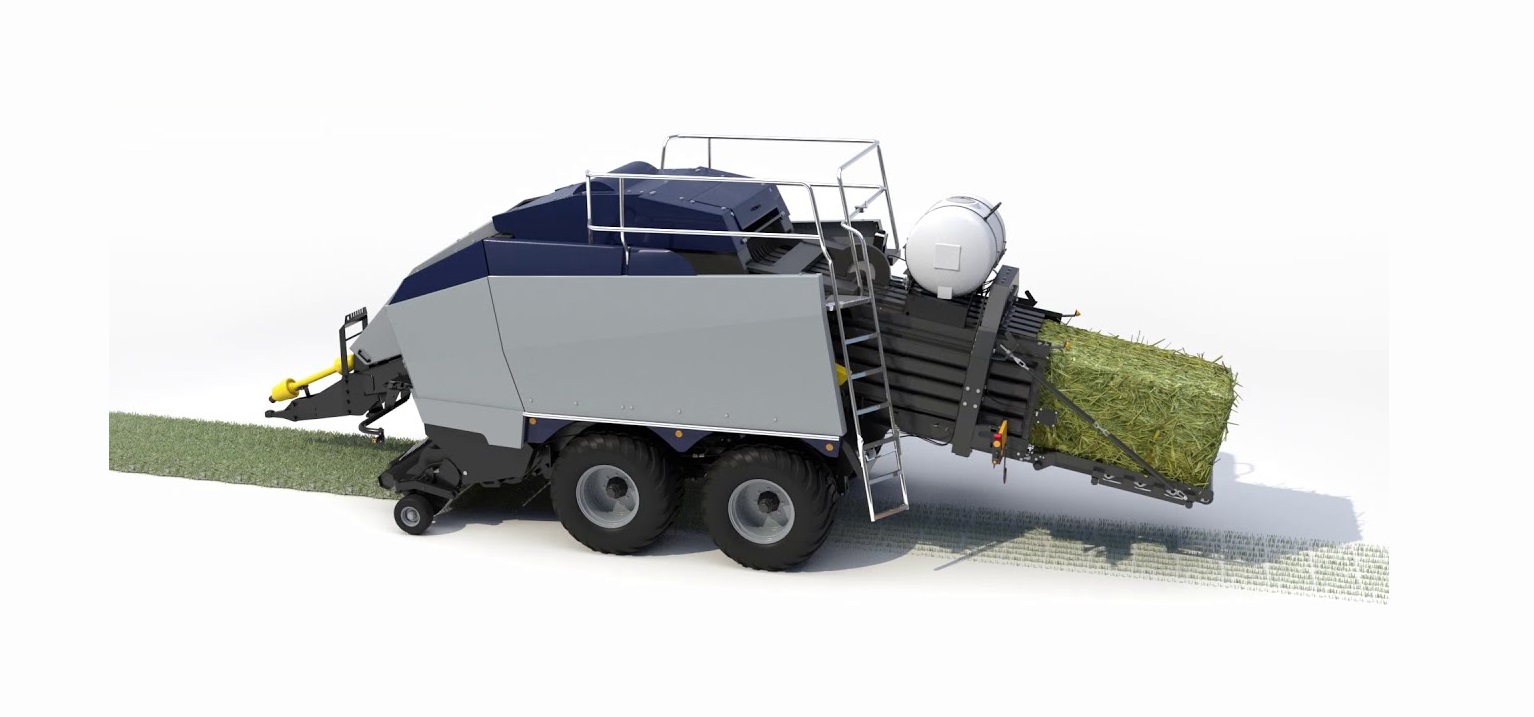
IntroductionThank you for purchasing a Harvest Tec Model 695 Hay Preservative Applicator. This 695 applicator system has been designed to be operated through an Apple iPad (not included) using the Hay App. As well as the option to plug directly into most tractors that have an ISOBUS Monitor. The 695 Applicator System offers these advantages by operating through an Apple iPad:1. Large bright, clear, colorful display 2. More durable and can be read in bright sunlight 3. Wireless connection in cab 4. Can be used for multiple other uses than just the applicator display 5. Option to tie-into the tractor ISOBUS systemThe 695 Hay Preservative Applicator System is designed to apply buffered propionic acid to the forage crop as it is baled and will adjust the rate of application based on moisture and tonnage of the crop being harvested. The model 695 base kit includes: tank, frame, pumps, hose, and the Dual Channel Processor (DCP). This manual will take you through the steps for installing the applicator. If you are unsure about installing the system after consulting this manual, contact your local authorized dealership for additional assistance. If you are in need of parts for the system please see the parts breakdown in the back of this manual and contact your local authorized dealer to order the parts. This applicator is designed to apply Harvest Tec buffered propionic acid.Right and Left sides are determined by facing in the direction of forward travel.*Requirement to run iPad running the current iOS operating system or one version previous.
Tools Needed:– Standard wrench set – Electric drill and bits – Side cutter – Crescent wrench – Standard screwdriver – Center punch
– Standard nut driver set – Standard socket set – Hammer – Metal cutting tools – Hose cutter
4
Installation of Applicator Tank Saddle & Pump Plate
Tank Saddle 001-6706A
Saddle Legs 001-6706Q
Pump Plate 001-4646D
Pump Plate Mount 001-4646CPump controller 006-5672
Locate parts bag 3. Install both saddle legs (001-6706Q) onto the saddle (001-6706A) with six 3/8″ x 1-1/4″ bolts, locks and flat washers. The mounting slots in the legs will attach to the second and third weld nuts in from each end, of the saddle, on both sides. 1. Once legs and saddle are loosely attached measure the distance from the top outside corners of the balechamber where the saddle will be attached. Move legs in or out so the inside edges will match this dimension. Also try to center the saddle within these dimensions. Do not fully tighten down bolts until unit is mounted on the baler. 2. Connect the pump plate mounting bracket (001-4646C) to the saddle. Using two 3/8″ x 1-1/4″ bolts, lock & flat washers. Note: this will be the side that is opposite of the “V” notch that is in the sump cut out of the saddle. 3. Attach the pump plate holder (001-4646D) to the pump plate mounting bracket (001-4646C) using four 3/8″ x 3/4″ flange head bolts.
5
Installation of Dual Channel Processor (DCP) Locate the Dual Channel Processor (006-6671) and the four predrilled holes on the left side of the baler near the flywheel as shown below. Use four 5/16″ x3″ hex bolts with four flat washers (positioning bolt heads on the inside of the baler frame) and secure to the baler with four 1 1/8″ threaded standoffs that will be on the outside of the baler frame. Position four fender washers between the DCP and standoffs. Mount the DCP with the display cable down toward the baler. Attach lock washers and hex nuts to mount the DCP (do not tighten). Before tightening hardware install the DCP shield (001-5650X) over the top two 5/16″ bolts between the fender washers and the mounting plate of the DCP. Tighten All Hardware6
Installation of Tank and Star Wheel Moisture Sensors Claas 3200-3400 Large Square Balers continued Star Wheel Mounting Use the picture below as a guide for drilling the mounting holes for the star wheels. The star wheels are to be mounted on the side of the bale chamber, between the top and middle channel. Measure 10″ back from the hinge between the top and middle channel. Cut 1″ x 9″ (25mm x 23cm) slot for the star wheel. Make sure the wheel is square. Mark the location of the two 5/16″ holes for the star wheel base. After drilling the holes, insert the 5/16″ x 3 1/4″ allen head bolts through the chute and use nuts to hold the bolts in place. Place the star wheel block over the nuts and install the prox sensor holder (001-4644H) on the star wheel located on the right side of the baler. Note: Thicker side of block goes to baler side.7
Installation of End of Bale Sensor The end of bale sensor determines the position of the needles on the baler. When the needles cycle the sensor communicates this information to the Dual Channel Processor (DCP). This information is used for job records and will be used by the optional Bale Identification System. Follow the steps below for your baler to mount the sensor. End of bale sensor bracket (001-4648) will be used. Cutoff excess metal not used during installation.001-4648 with 12″ (30cm) hole used for sensorInstallation of the Drain/Fill Line 1. Locate parts bag 1. 2. Thread 3/4″ elbow fitting into end of tank. 3. Run hose from the elbow down the frame to the bottom of the baler. 4. Drill 1/4″ (7mm) holes to accept the valve holder bracket and use 5/16″ x 1″ self-tapping screws. 5. Connect valve assembly to other end of hose. Place hose clamps on both ends. 6. Secure hose to frame using cable locks. 7. Install supplied safety decals (DCL-8001 & DCL-8005) next to the ball valve assembly.8
Installation of Spray ShieldThe spray shield assembly is designed to spray the hay evenly as the baler picks it up. A sketch of the spray shield nozzle holder is shown below.
Tip Outputs
High Output Tips for Rates Requiring 84-632 lbs/hr (38-287 L/hr) . (Approximately 21-63 tons/hr)
Install Kits 4537B
Gray / Red tips (Part #: 004-T8003-PT)Silver tips (Part #: 004 T80015-PT) Silver tips (Part #: 004-T8001-PT)
–Blue Hose –Green Hose –Clear Hose
Low Output Tips for Rates Requiring 44-400 lbs/hr (19-200 L/hr). (Approximately 11-40 tons/hr)
Install Kits 4537B
Silver / Brown tips (Part #: 004-T80015-PT) –Blue Hose
Silver tips (Part #: 004-T8001-PT)
–Green Hose
Silver tips (Part #: 004-800067-SS)
–Clear Hose
Installation Kit 4537BThe spray shield holder (001-4435L) is centered on the L-shaped bracket above the rotor and secured with 3/8″x1-1/4″ hex bolts, 3/8″ lock washers, and 3/8″ nuts (x3). The spray shield is then pinned in place with the lynch pins. Route hoses so they do not interfere with moving parts, and do not fasten hoses to hydraulic lines.
Auger
RotorL-shaped bracket
9
Plumbing A. Locate the three 1/4″ hoses colored clear, blue, and green. The pumps will need to be connected tospecific tips so the pump numbers are as follows: Pump 1 is closest to the filter bowl, pump 2 is in the middle, and pump 3 is the outside pump. B. Slide the jaco nut over the end the hose and insert the hose into the jaco fitting and tighten the jaco nut. Because all nozzles on the spray shield are different, the operator will need to install pump 1 to the orange tips using the clear hose, pump 2 to the green tips using the green hose and pump 3 to the blue tips using the blue hose. C. KEEP HOSE AWAY FROM: MOVING PARTS, SHARP METAL, AND HYDRAULIC LINES. WORKING TEMPERATURE FOR THE HOSE IS 140 oF AND UNDER. D. Tie the hose down at secure locations on the baler using the enclosed tie straps and cable clamps.Installation of star wheel and bale rate harness Remove the cover from the star wheel block and use a 1/4″ nut driver to remove the nut from the electronic swivel. Next, run the star wheel sensor wire through the black grommet and place the eye terminal on the star wheel sensor. Tighten the eye loop with the nut on the sensor and put the star wheel cover back on the base. Tighten the grommet to form a tight seal around the wire. The bale rate sensors will be factory installed on the right side twine guard in the correct position. The sensor with the longer sensor wire should say “FRONT” which indicates it should be placed in the front sensor hole. The sensor wire with the shorter wire should say “BACK.” The tip of the sensor should be placed no more than 1/4″ (7mm) away from the star wheel teeth and no less than 1/8″ (3mm) from the star wheel teeth. Each sensor will have an LED light located on the sensor by the diverter. Once the unit is powered up spin the wheel and make sure that both led lights turn on and off. If they don’t turn on and off, adjustments may need to be made. Once the star wheel connection is complete, run the harness along the baler frame to the Dual Channel Processor (DCP). See wiring installation on the following page. The Dual Channel Processor is located on the back of the right twine box.10
Installation of iPad Integration Control Locate a safe location in the cab of the tractor to place the iPad Integration Control (030-6672C). Recommended location is securely fastened out of the operators way in a location that is close enough to reach with the iPad cord. Connect the Power / Communication harness (006-6650TM(E)) to the bottom of the receiver. To operate the applicator, plug the iPad cord into the communication port indicated by:iPad Integration Control Light Signals Green Slow Blink Power supplied to the applicator system and the unit is going through its startup process. This will take approximately 25-35 seconds. Green Double Blink Indicating the iPad module recognizes the iPad but the app is not open or connected. Green Solid Light Module is connected to the app and is ready to operate. *Recommended to use the USB cable included with the applicator kit (006-6672USBC) **600 Series Applicators with serial number before DCP26000 will require the DCP to be sent to HarvestTec for a required update in order to use the iPad Integration Module (030-6670C).Bluetooth Receiver Lights Pre-2020 applcaitors equipped with Bluetooth receivers (030-6672B) are now equipped with lights to indicate both power and Hay App connection on the Apple iPad. Clean light regularly Blinking Lights System is waiting for the processor to connect, which could take up to 35 seconds. Red Light The Bluetooth receiver has power Green Light The Bluetooth receiver is connected to the Hay App.11
Connecting the optional ISOBUS plug to the tractor Attach the optional ISOBUS connector 006-6670A (not included) to the end of the communication harness 006-6650TM. Connect the orange wires and attach the plug to the tractor’s ISOBUS port. Then connect the ISOBUS connector to the ISOBUS plug on the tractor.12
Wiring Diagram
1. The Baler Power/Communication Harness (006-6650LS(E)) will attach to the open port of the Tractor Harness (006-6650TM(E)) and run back to the Dual Channel Processor (006-6671LS). Connect the large plug of the Baler Power/Communication Harness (006-6650LS) to the bottom (shorter side) of the DCP.2. Install green terminator (006-5650Z) to the port labeled Modular Port on the Pump Controller (006-5672). 3. Attach moisture and bale rate harness 006-7303H(E) (Claas & Krone kits 006-7303HX(E)) as well as the end ofbale harness (006-7400) to the DCP (006-6671LS). 4. Attach the Pump Control Harness (006-5650F2M(E)) between the Pump Controller (006-5672) and the DCP(006-6671LS). 5. Connect the orange wires and attach the plug to the tractor’s ISOBUS port. 6. If using the optional ISOBUS connector (006-6670A) connect the end to the Communication Harness (006-6650TM(E)) in place of the iPad Integration Control shown below (030-6672C). 7. Connect the orange keyed power wires (006-5650K) and attach the plug to the tractor’s ISOBUS port.
Star Wheel Assembly (x2)030-4641U
Proximity Sensor (2X) 006-7303S
Moisture/Bale Rate Harness 006-7303H(E)(006-7303HX(E) Claas & Krone)Data Transfer
Dual Channel Processor (DCP)006-6671LS
End of Bale Sensor 006-7400Flow Meter 006-4725A
Optional Port
Pump Harness 006-4660ZOrange Wires to Keyed Power006-5650K
Pump Controller 006-5672Terminating Resistor 006-5650ZiPad Integration Control 030-6672C
Pump Controller Harness 006-5650F2M(E)
Power/Comm Harness on Baler 006-6650LS(E)
Power/Comm Harness on Tractor 006-6650TM(E)
*Note: (E) indication is used for International Dealers
13
Pin Outs
Power/Comm Harness 006-6650TM(E) at Hitch
Pin 1 Red
+12V Power to TSD
Pin 2 Red
+12V Power to DCP
Pin 3 Orange
Keyed Power
Pin 4 Gray
Shield
Pin 5 Green
HT Can Low
Pin 6 Yellow
HT Can Hi
Pin 7 Orange
Can1 Hi
Pin 8 Black
Ground from TSD
Pin 9 Black
Ground from DCP
Pin 10 Blue
Can1 Low
Power/Comm Harness 006-6650LS2(E) at Hitch
Pin 1 Red
+12V Power to TSD
Pin 2 Red
+12V Power to DCP
Pin 3 Orange
Keyed Power
Pin 4 Gray
Shield
Pin 5 Green
HT Can Low
Pin 6 Yellow
HT Can Hi
Pin 7 Orange
Can1 Hi
Pin 8 Black
Ground from TSD
Pin 9 Black
Ground from DCP
Pin 10 Blue
Can1 Low
Bluetooth Receiver on Harness 006-6650TM(E)
Pin 1 Red
+12V Power from DCP
Pin 2 Black
Ground from TSD
Pin 3 Yellow
HT Can Low
Pin 4 Gray
Shield
Pin 5 Green
HT Can Hi
Pin 6 Orange
Can1 Hi
Pin 7 Blue
Can1 Low
ISOBUS Plug Baler Side
Pin 1
N/A
Pin 2
N/A
Pin 3
120 OHM with Pin 5
Pin 4
N/A
Pin 5
120 OHM with Pin 3
Pin 6 Orange
Can1 Hi
Pin 7 Blue
Can1 Low
ISOBUS Plug Tractor Side
Pin 1
N/A
Pin 2
N/A
Pin 3
+12V Keyed Tractor Power
Pin 4
N/A
Pin 5
Pin 6
N/A
Pin 7
N/A
Pin 8 Orange
Can1 Hi
Pin 9 Blue
Can1 Low
14
2
1
3
4 5 67
8 9 10
21 5437 6
Pin Outs (continued)
Main Power Connector on DCP
Pin 1 Red
+12V Power from tractor
Pin 2 Black
Ground from tractor
Pin 3 Orange
Keyed power
Star Wheel and Bale Rate Sensor connector on DCP
Pin 1 Blue
+12V Power
Pin 2 Orange
Ground
Pin 3 Black
Signal for sensor 1
Pin 4 White
Signal for sensor 2
Pin 5 N/A
Pin 6 N/A
Pin 7 N/A
Pin 8 Violet
Star wheel input 1
Pin 9 Brown
Star wheel input 2
End of Bale sensor on DCP
Pin 1 Brown
Sensor Power
Pin 2 Blue
Sensor Ground
Pin 3 N/A
Pin 4 Black
Signal from Sensor
Pump Connection Colors Pin 1 Black with Orange Stripe Pin 2 Black with Green Stripe Pin 3 Black with Yellow Stripe Pin 4 N/A Pin 5 Orange with Black Stripe Pin 6 Green with Black Stripe Pin 7 Yellow with Black Stripe
Pump 1 Ground Pump 2 Ground Pump 3 GroundPump 1 Positive Pump 2 Positive Pump 3 Positive
006-6650VAJ Harness to Baler Plug (John Deere Integration)
Pin A N/A
Pin B Red
TBC Power
A
Pin C N/A
Pin D Gray
TBC Ground
Pin E Orange
Can1 Hi
D
Pin F Blue
Can1 Low
15
Pin Outs (continued)
Pump Communication Plug on DCP
Pin 1 Red
+12V Can
Pin 2 Red
+12V Power
Pin 3 Gray
Shield
Pin 4 Green
Comm Channel OH
Pin 5 Yellow
Comm Channel OL
Pin 6 Blue
Comm Channel IH
Pin 7 Orange
Comm Channel IL
Pin 8 Black
Can Ground
Pin 9 Black
Power Ground
Pin 10 N/A
Flow Meter Connection on Pump Controller
Pin 1 White
5 12V (+) Supply
Pin 2 Green
Ground
Pin 3 Brown
Signal
Pin 4 Black
Shield
Connector for Crop Eyes on DCP
Pin 1 Red
+12V Power
Pin 2 Black
Ground
Pin 3 White
Signal
Pin 4 N/A
006-6650VAK Harness to Baler (Krone Integration)
Pin 1 Red
Power
Pin 2 Orange
CAN1_H
Pin 3 Black
RTN
Pin 4 Blue
CAN1_L
Pump Communication Plug on DCP
Pin 1 Red
+12V Can
Pin 2 Black
+12V Power
Pin 3 Yellow
Shield
Pin 4 Gray
Comm Channel OH
Pin 5 Green
Comm Channel OL
Pin 6 Orange
Comm Channel IH
Pin 7 Blue
Comm Channel IL
16
1
3
2
4
Parts Breakdown Tank, Saddle & Legs 100 Gallon12 3
5
4
Ref Description Part#
Qty
1 Tank Lid 6″
005-9022C 1
2 Tank 100 Gal 005-9206
1
3 Tank Straps
001-4402
2
4 Tank Saddle 001-6706A 1
Ref Description
Part#
Qty
5 3/4″ Tank Fitting 005-9100
1
NP 3/4″x1/2″ Elbow 003-EL3412 1
NP Cap Gasket
005-9022CG 1
Claas 5300 Saddle Legs (x2) Part: 001-6706Q
17
Parts Breakdown for Pump Manifold
1
6 10 14
13
12
15
2 183
12c
12b
4
5
9
12a
11
6
7
17
8
Ref# Description
Part#
Qty
1 Pump plate
001-4646D
1
2 Mounting Bracket
001-4646C
1
3 Pump
007-4120H
3
4 Street elbow fitting
003-SE38
3
5 Nipple fitting
003-M3838
3
6 Check valve
002-4566F
3
7 Elbow fitting
003-EL3812
1
8 Tee fitting
003-T3812HB
2
9 Flow meter assembly
006-4725A
1
10 Straight fitting
003-A1212
2
11 Jaco fitting
003-JEL1238
3
12 Filter bowl assembly
002-4315-100
1
12a Filter bowl only
002-4315F
1
12b Filter bowl gasket
002-4315D
1
12c Filter bowl screen
002-4315A
1
13 Nipple fitting
003-M1212
1
14 Ball valve
002-2212
1
15 Street elbow fitting
003-SE12
1
16 Hose clamp
003-9003
7
17 Hose clamp (Flow Meter)
003-9005
2
18 Pump Cable
006-4660Z
1
NP Elbow
003-EL1212
1
NP Pump rebuild kit (1 per pump) 007-4581
1
Complete Pump Assembly
030-4646
18
Star Wheel Moisture Sensors
1
Ref Description
Part#
Qty
1 Univ Star Wheel
006-4641S
1
2 Dust Seal
006-4641DSL 2
2
4
3
3 Univ Star Block
006-4641Q
1
4 3/8″ NPT Cable Grip 008-0821A
1
5 3/8″ NPT Plug
003-F38
1
6 Thrust Washer
006-4641TA 2
10
7 Thrust Bearing 8 Swivel Insert
006-4641TB 1
006-4642B
1
9 3/4″ Short Nut
006-4641U
1
10 Rotary Swivel
006-4642A
1
2
5
6
11 Cover Gasket 12 Univ Block Cover
006-4641RG 1
006-4641R
1
7
NP Twine Diverter (right) 001-4644
1
NP Twine Diverter (left) 001-4645
1
8
9
Complete Assembly
030-4641U
2
11
(Ref 1-12)
12
Bale Rate Sensors & Harness
12
Ref Description
12 Bale rate sensor
Part#
Qty
006-7303S
2
13 Moisture and bale rate harness 006-7303HX(E) 1
*Note: (E) indication is used
13
for International Dealers
19
Parts Breakdown for 695 Series Control and HarnessesDual Channel Processor (DCP)
5
7
9
1
3
2
4
6
8
10
1211
Ref Description 1 Modular Power/Comm 15 FT Harness 2 Dust Plugs 3 DCP Baler Harness 15 FT 4 Key Switch Wire 5 EOB Extension for CNH BB Series 6 Terminating Connector 600 Series 7 End of Bale Sensor Bracket 8 End of Bale Sensor 600 Series 9 DCP Shield/Cover 10 DCP Main Control LS 600 AUTO 11 Pump Controller 12 DCP Tractor Harness
Part Number
Qty
006-5650F2M(E) 1
006-5651PLUGS 1
006-6650LS
1
006-5650K
1
006-7400BBEXT 1
006-5650Z
1
001-4648
1
006-7400
1
001-5650X
1
006-6671LS
1
006-5672
1
006-6650TM(E) 1
iPad Integration Control
*Note: (E) indication is used for International Dealers
Part #: 030-6672C
20
Parts Breakdown for Hose and Drain Fill Line
4
5
10
3
2
1
9
11
7 6
8
12
Ref Description 1 Triple weld hose (pumps to tips)Three hose assembly 2 1/2″ Hose (tank to filter) 3 3/4″ Hose (tank to drain/fill valve) 4 Straight Fitting 5 Elbow 6 Hose Clamps #10
Part#
Qty
002-9016
15ft
002-9016B 15ft
002-9016G 15ft
030-9016RB 1
002-9001
20ft
002-9002
10ft
003-A3434 1
003-EL3434 1
003-9004
2
Ref Description 7 Female Coupler 8 Male Coupler 9 Valve Holder 10 Ball valve 11 Jiffy Clip 12 Hose Clamp #6
Part#
Qty
002-2204A 1
002-2205G 1
001-6702H 1
002-2200
1
008-9009
7
003-9003
2
21
Optional iPad Mini Mounting Kit (030-2014MK)
2 13
4
7 5
6
8
Ref Description 1 Suction cup mount 2 Ram mount 3 iPad Mini spring load cradle (Mini 4) 4 16 gauge power wire 5 Female spade connector 6 Eye loop connector 7 iPad Mini Charger 12V 8 iPad Mini 4 case NP 4 amp fuse
Part #
Qty
001-2012SCM
1
001-2012H
1
001-2012SLC
1
006-4723P
1
Hardware
2
Hardware
2
001-2012P
1
001-2012C4
1
Hardware
1
Mounting Kit Assembly Installation Instructions
030-2014MK (Includes All Parts)
1. Identify 12V power source for wires to connect. a. Eye loops included if wiring directly to the battery is desired. b. Test for key power source if preferred to have power to the USB shut off with the key.2. Once power source is identified, cut wires to desired length. 3. Crimp the two supplied quick connectors onto each the white and black wire. 4. Remove the round locking plastic nut from USB plug before connecting the wires. Black (+) White (-). 5. The wires will then be hooked to the designated terminals on the bottom of the USB plug 6. Drill a 1 1/8″ hole in the preferred mounting location. Be sure to clean any sharp edges after drilling. 7. Feed the wires through the mounting hole. 8. If using the round plastic nut to secure plug in place, slide the nut back over the wiring beforeconnecting the wires to powered source. 9. Connect the wires to the identified power source if easier to do so before tightening the plug into place. 10. Tighten plug using either the round plastic nut or mounting plate and two screws, both options supplied. 11. Once connected, hook a USB charging cord into the plug and connect a mobile device/tablet to ensurethe plug is operating as you wish (key power working properly if necessary).NOTE: This plug is not designed to charge two iPads. System damage could occur if this is attempted. System will charge a mobile phone and iPad simultaneously without problem.
22
Optional iPad Display Kit (030-4670DK)
9 2 13
7
4
5
6
8
Ref Description
Part #
Qty
1 Suction cup mount
001-2012SCM 1
2 Ram mount
001-2012H
1
3
iPad Mini spring load cradle (Mini 4)
001-2012SLC 1
4 16 gauge power wire
006-4723P
1
5 Female spade connector Hardware
2
6 Eye loop connector
Hardware
2
Ref Description
Part #
Qty
7 iPad Mini Charger 12V 001-2012P 1
8 iPad Mini 4 case
001-2012C4 1
9 iPad Mini 4
006-4670IP 1
NP 4 amp fuse
Hardware
1
Mounting Kit Assembly
030-4670DK (Includes All Parts)
Installation Instructions
1. Identify 12V power source for wires to connect. a. Eye loops included if wiring directly to the battery is desired. b. Test for key power source if preferred to have power to the USB shut off with the key.2. Once power source is identified, cut wires to desired length. 3. Crimp the two supplied quick connectors onto the white and black wire. 4. Remove the round locking plastic nut from USB plug before connecting the wires. Black (+) White (-). 5. The wires will then be hooked to the designated terminals on the bottom of the USB plug 6. Drill a 1 1/8″ hole in the preferred mounting location. Be sure to clean any sharp edges after drilling. 7. Feed the wires through the mounting hole. 8. If using the round plastic nut to secure plug in place, slide the nut back over the wiring before connectingthe wires to powered source. 9. Connect the wires to the identified power source if easier to do so before tightening the plug into place. 10. Tighten plug using either the round plastic nut or mounting plate and two screws, both options supplied. 11. Once connected, hook a USB charging cord into the plug and connect a mobile device/tablet to ensure theplug is operating as you wish (key power working properly if necessary).NOTE: This plug is not designed to charge two iPads. System damage could occur if this is attempted. System will charge a mobile phone and iPad simultaneously without problem.
23
4537B Installation Kit120
Ref Description Part Number
1 Holder
001-4435L
2 Shield
001-4435NSX
3 Fitting
003-F14
4 Manifold Block 001-4435NSB
5 Lynch Pin
008-4576
6 Tip-Red
004-T8003-PT
7 Tip-Brown
004-T80015-PT
8 Tip-Pink
004-T8001-PT
9 Tip-Stainless 004-T800067-SS
10 Hose Clamp 003-9002
Qty Ref Description
Part Number Qty
1 11 Cap
004-4723
3
1 12 Fitting
003-A1414VB 3
3 13 Strainer
004-1203-100 3
2 14 Check Valve
004-1207VB 3
2 15 Fitting
003-A1414F 3
2 16 Clear Tubing-1/4″ 002-9016
3ft
2 17 Blue Stripe Tubing 002-9016B
3ft
2 18 Green Stripe Tubing 002-9016G
3ft
2 19 EVA-1/4″
002-9006
3ft
15 20 Fitting
003-A1414
9
NP Mini Plano Box
008-9001
1
24
Harvest Tec LLC. Warranty and Liability AgreementHarvest Tec, LLC. will repair or replace components that are found to be defective within 12 months from the date of manufacture. Under no circumstances does this warranty cover any components which in the opinion of Harvest Tec, LLC. have been subjected to negligent use, misuse, alteration, accident, or if repairs have been made with parts other than those manufactured and obtainable from Harvest Tec, LLC. Our obligation under this warranty is limited to repairing or replacing free of charge to the original purchaser any part that in our judgment shows evidence of defective or improper workmanship, provided the part is returned to Harvest Tec, LLC. within 30 days of the failure. If it is determined that a non-Harvest Tec branded hay preservative has been used inside the Harvest Tec applicator system where the failure occurred, then Harvest Tec reserves the right to deny the warranty request at their discretion. Parts must be returned through the selling dealer and distributor, transportation charges prepaid. This warranty shall not be interpreted to render Harvest Tec, LLC. liable for injury or damages of any kind, direct, consequential, or contingent, to persons or property. Furthermore, this warranty does not extend to loss of crop, losses caused by delays or any expense prospective profits or for any other reason. Harvest Tec, LLC. shall not be liable for any recovery greater in amount than the cost or repair of defects in workmanship. There are no warranties, either expressed or implied, of merchantability or fitness for particular purpose intended or fitness for any other reason. This warranty cannot guarantee that existing conditions beyond the control of Harvest Tec, LLC. will not affect our ability to obtain materials or manufacture necessary replacement parts. Harvest Tec, LLC. reserves the right to make design changes, improve design, or change specifications, at any time without any contingent obligation to purchasers of machines and parts previously sold. Revised 4/1725
 report this ad
HARVEST TEC, LLC. P.O. BOX 632821 HARVEY STREET HUDSON, WI 54016PHONE: 715-386-9100 1-800-635-7468FAX: 715-381-179226
[xyz-ips snippet=”download-snippet”]